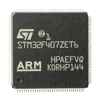
STM32F417ZGT6 - ARM Cortex-M4F MCU 1MB Flash 168MHz | STMicroelectronics
MPN: STM32F417ZGT6 ✓ 啟用中STM32F417ZGT6 概覽
What is an ARM Cortex-M4F microcontroller? It is a 32-bit processor core designed for embedded systems, combining the efficiency of the Cortex-M4 with a hardware floating-point unit (FPU) that accelerates single-precision math operations. This makes it ideal for digital signal processing (DSP) and control applications. In the system hierarchy, the STM32F417ZGT6 sits at the application processor level, integrating memory, clocking, and a rich set of peripherals on a single chip, reducing system cost and board space.
Key features include a 168 MHz maximum clock speed, 1 MB Flash, 192 KB SRAM, and a comprehensive set of peripherals: 3x 12-bit ADCs (2.4 MSPS), 2x DACs, 12-bit DAC, 2x I2C, 3x SPI, 4x USART, 2x UART, 2x CAN, 1x USB 2.0 OTG FS/HS, 1x Ethernet MAC, 1x camera interface, and a true random number generator (RNG). The FPU accelerates control algorithms and audio processing. The device also includes a memory protection unit (MPU) and a cryptographic acceleration cell for AES, DES, and 3DES.
Technically, the STM32F417ZGT6 is built on a 90nm process, offering a balance of performance and power consumption. It operates from 1.8V to 3.6V supply, with a wide temperature range of -40°C to +85°C (industrial grade). The device supports various low-power modes (Sleep, Stop, Standby) to optimize energy consumption in battery-powered applications. The advanced nested vectored interrupt controller (NVIC) ensures low-latency interrupt handling, critical for real-time control.
Typical applications include industrial motor control, medical devices, consumer electronics, IoT gateways, and audio processing. The Ethernet MAC and USB OTG enable connectivity, while the FPU and DSP instructions make it suitable for real-time audio and vibration analysis. The camera interface supports image capture for vision-based systems.
When designing with this MCU, ensure adequate decoupling on the VDD pins and a clean analog supply for the ADC. The internal RC oscillator is sufficient for many applications, but an external crystal is recommended for precise timing. The boot pins must be configured correctly to select the boot source (Flash, SRAM, or system memory).
直接替換替代品,適用於 STM32F417ZGT6 — 相同封裝,腳位對腳位相容。需重新設計 PCB 的不同封裝零件不列入。
此系列的變體
與下列產品可直接替換的同系列型號: STM32F417ZGT6 (相同外形與佔位) — 差異在於 ADC, Communication Interfaces, Package, SRAM, Timers.
STM32F407ZGT6
✅ 直接替換✓ 有庫存
$5.25 / 單位
查看資料表 →STM32F417ZGT7
✅ 直接替換 ⚠️ 規格未經驗證📋 參考替代品(不在目錄中)
STM32F417ZGT6TR
✅ 直接替換 ⚠️ 規格未經驗證📋 參考替代品(不在目錄中)
STM32F427ZGT6
✅ 直接替換 ⚠️ 規格未經驗證📋 參考替代品(不在目錄中)
LPC4088FBD144
⚡ 相同封裝 ⚠️ 規格未經驗證聯絡詢價
查看資料表 →STM32F417ZGT6 最大額定值與電氣特性
| Core | ARM Cortex-M4F with FPU |
| Max Clock Speed | 168 MHz |
| Flash Memory | 1 MB |
| SRAM | 192 KB |
| 供應電壓 | 1.8 V to 3.6 V |
| 封裝 | LQFP144 (20x20 mm) |
| 工作溫度 | -40C to +85C |
| ADC | 3x 12-bit, 2.4 MSPS |
| DAC | 2x 12-bit |
| Communication Interfaces | I2C, SPI, USART, UART, CAN, USB OTG, Ethernet MAC |
| GPIO Pins | 114 |
| Timers | 12x 16-bit, 2x 32-bit |
| DMA | 2x DMA controllers with 16 streams |
| RNG | True random number generator |
| Cryptographic Acceleration | AES, DES, 3DES |
| RoHS 狀態 | Compliant |
STM32F417ZGT6 腳位配置
| 腳位 1 | PE2 — GPIO or alternate function |
| 腳位 2 | PE3 — GPIO or alternate function |
| 腳位 3 | PE4 — GPIO or alternate function |
| 腳位 4 | PE5 — GPIO or alternate function |
| 腳位 5 | PE6 — GPIO or alternate function |
| 腳位 6 | VBAT — Battery backup supply |
| 腳位 7 | PC13 — GPIO or RTC output |
| 腳位 8 | PC14 — GPIO or OSC32_IN |
| 腳位 9 | PC15 — GPIO or OSC32_OUT |
| 腳位 10 | PF0 — GPIO or alternate function |
| 腳位 11 | PF1 — GPIO or alternate function |
| 腳位 12 | PF2 — GPIO or alternate function |
| 腳位 13 | PF3 — GPIO or alternate function |
| 腳位 14 | PF4 — GPIO or alternate function |
| 腳位 15 | PF5 — GPIO or alternate function |
| 腳位 16 | PF6 — GPIO or alternate function |
| 腳位 17 | PF7 — GPIO or alternate function |
| 腳位 18 | PF8 — GPIO or alternate function |
| 腳位 19 | PF9 — GPIO or alternate function |
| 腳位 20 | PF10 — GPIO or alternate function |
| 腳位 21 | VSS — Ground |
| 腳位 22 | VDD — Power supply |
| 腳位 23 | PF11 — GPIO or alternate function |
| 腳位 24 | PF12 — GPIO or alternate function |
| 腳位 25 | PF13 — GPIO or alternate function |
| 腳位 26 | PF14 — GPIO or alternate function |
| 腳位 27 | PF15 — GPIO or alternate function |
| 腳位 28 | PG0 — GPIO or alternate function |
| 腳位 29 | PG1 — GPIO or alternate function |
| 腳位 30 | PG2 — GPIO or alternate function |
| 腳位 31 | PG3 — GPIO or alternate function |
| 腳位 32 | PG4 — GPIO or alternate function |
| 腳位 33 | PG5 — GPIO or alternate function |
| 腳位 34 | PG6 — GPIO or alternate function |
| 腳位 35 | PG7 — GPIO or alternate function |
| 腳位 36 | PG8 — GPIO or alternate function |
| 腳位 37 | PG9 — GPIO or alternate function |
| 腳位 38 | PG10 — GPIO or alternate function |
| 腳位 39 | PG11 — GPIO or alternate function |
| 腳位 40 | PG12 — GPIO or alternate function |
| 腳位 41 | PG13 — GPIO or alternate function |
| 腳位 42 | PG14 — GPIO or alternate function |
| 腳位 43 | PG15 — GPIO or alternate function |
| 腳位 44 | VSS — Ground |
| 腳位 45 | VDD — Power supply |
| 腳位 46 | PD0 — GPIO or alternate function |
| 腳位 47 | PD1 — GPIO or alternate function |
| 腳位 48 | PD2 — GPIO or alternate function |
| 腳位 49 | PD3 — GPIO or alternate function |
| 腳位 50 | PD4 — GPIO or alternate function |
| 腳位 51 | PD5 — GPIO or alternate function |
| 腳位 52 | PD6 — GPIO or alternate function |
| 腳位 53 | PD7 — GPIO or alternate function |
| 腳位 54 | PD8 — GPIO or alternate function |
| 腳位 55 | PD9 — GPIO or alternate function |
| 腳位 56 | PD10 — GPIO or alternate function |
| 腳位 57 | PD11 — GPIO or alternate function |
| 腳位 58 | PD12 — GPIO or alternate function |
| 腳位 59 | PD13 — GPIO or alternate function |
| 腳位 60 | PD14 — GPIO or alternate function |
| 腳位 61 | PD15 — GPIO or alternate function |
| 腳位 62 | VSS — Ground |
| 腳位 63 | VDD — Power supply |
| 腳位 64 | PC0 — GPIO or ADC input |
| 腳位 65 | PC1 — GPIO or ADC input |
| 腳位 66 | PC2 — GPIO or ADC input |
| 腳位 67 | PC3 — GPIO or ADC input |
| 腳位 68 | PC4 — GPIO or ADC input |
| 腳位 69 | PC5 — GPIO or ADC input |
| 腳位 70 | PB0 — GPIO or ADC input |
| 腳位 71 | PB1 — GPIO or ADC input |
| 腳位 72 | PB2 — GPIO or alternate function |
| 腳位 73 | PB3 — GPIO or alternate function |
| 腳位 74 | PB4 — GPIO or alternate function |
| 腳位 75 | PB5 — GPIO or alternate function |
| 腳位 76 | PB6 — GPIO or alternate function |
| 腳位 77 | PB7 — GPIO or alternate function |
| 腳位 78 | PB8 — GPIO or alternate function |
| 腳位 79 | PB9 — GPIO or alternate function |
| 腳位 80 | PB10 — GPIO or alternate function |
| 腳位 81 | PB11 — GPIO or alternate function |
| 腳位 82 | PB12 — GPIO or alternate function |
| 腳位 83 | PB13 — GPIO or alternate function |
| 腳位 84 | PB14 — GPIO or alternate function |
| 腳位 85 | PB15 — GPIO or alternate function |
| 腳位 86 | VSS — Ground |
| 腳位 87 | VDD — Power supply |
| 腳位 88 | PA0 — GPIO or ADC input |
| 腳位 89 | PA1 — GPIO or ADC input |
| 腳位 90 | PA2 — GPIO or ADC input |
| 腳位 91 | PA3 — GPIO or ADC input |
| 腳位 92 | PA4 — GPIO or ADC input |
| 腳位 93 | PA5 — GPIO or ADC input |
| 腳位 94 | PA6 — GPIO or ADC input |
| 腳位 95 | PA7 — GPIO or ADC input |
| 腳位 96 | PA8 — GPIO or alternate function |
| 腳位 97 | PA9 — GPIO or alternate function |
| 腳位 98 | PA10 — GPIO or alternate function |
| 腳位 99 | PA11 — GPIO or alternate function |
| 腳位 100 | PA12 — GPIO or alternate function |
| 腳位 101 | PA13 — GPIO or SWDIO |
| 腳位 102 | PA14 — GPIO or SWCLK |
| 腳位 103 | PA15 — GPIO or alternate function |
| 腳位 104 | VSS — Ground |
| 腳位 105 | VDD — Power supply |
| 腳位 106 | PH0 — GPIO or OSC_IN |
| 腳位 107 | PH1 — GPIO or OSC_OUT |
| 腳位 108 | PH2 — GPIO or alternate function |
| 腳位 109 | PH3 — GPIO or alternate function |
| 腳位 110 | PH4 — GPIO or alternate function |
| 腳位 111 | PH5 — GPIO or alternate function |
| 腳位 112 | PH6 — GPIO or alternate function |
| 腳位 113 | PH7 — GPIO or alternate function |
| 腳位 114 | PH8 — GPIO or alternate function |
| 腳位 115 | PH9 — GPIO or alternate function |
| 腳位 116 | PH10 — GPIO or alternate function |
| 腳位 117 | PH11 — GPIO or alternate function |
| 腳位 118 | PH12 — GPIO or alternate function |
| 腳位 119 | PH13 — GPIO or alternate function |
| 腳位 120 | PH14 — GPIO or alternate function |
| 腳位 121 | PH15 — GPIO or alternate function |
| 腳位 122 | VSS — Ground |
| 腳位 123 | VDD — Power supply |
| 腳位 124 | PI0 — GPIO or alternate function |
| 腳位 125 | PI1 — GPIO or alternate function |
| 腳位 126 | PI2 — GPIO or alternate function |
| 腳位 127 | PI3 — GPIO or alternate function |
| 腳位 128 | PI4 — GPIO or alternate function |
| 腳位 129 | PI5 — GPIO or alternate function |
| 腳位 130 | PI6 — GPIO or alternate function |
| 腳位 131 | PI7 — GPIO or alternate function |
| 腳位 132 | PI8 — GPIO or alternate function |
| 腳位 133 | PI9 — GPIO or alternate function |
| 腳位 134 | PI10 — GPIO or alternate function |
| 腳位 135 | PI11 — GPIO or alternate function |
| 腳位 136 | PI12 — GPIO or alternate function |
| 腳位 137 | PI13 — GPIO or alternate function |
| 腳位 138 | PI14 — GPIO or alternate function |
| 腳位 139 | PI15 — GPIO or alternate function |
| 腳位 140 | VSS — Ground |
| 腳位 141 | VDD — Power supply |
| 腳位 142 | PE0 — GPIO or alternate function |
| 腳位 143 | PE1 — GPIO or alternate function |
| 腳位 144 | VSS — Ground |
典型應用
STM32F417ZGT6 適用於 6 應用s: Industrial Motor Control, IoT Gateway, Medical Device, Audio Processing, Consumer Electronics, Test and Measurement.
Industrial Motor Control
The STM32F417ZGT6 is ideal for industrial motor control due to its advanced timers with complementary PWM outputs, dead-time insertion, and fault inputs. The 168 MHz Cortex-M4F core with FPU accelerates field-oriented control (FOC) algorithms, enabling high-performance, real-time control of three-phase motors. The device's 12-bit ADCs (2.4 MSPS) provide precise current and voltage sensing, while the CAN interface supports industrial networking. In a typical application, the MCU generates PWM signals to drive an IGBT inverter, reads motor currents via ADCs, and executes FOC in real-time. The FPU reduces computation time for complex math, improving control loop frequency. Design considerations include proper isolation for high-voltage sections and thermal management for the MCU.
推薦
IoT Gateway
The STM32F417ZGT6 serves as a powerful IoT gateway, integrating Ethernet MAC, USB OTG, and multiple UART/SPI interfaces for connecting sensors and actuators. The 1 MB Flash and 192 KB SRAM support complex protocol stacks (e.g., MQTT, TCP/IP) and local data processing. The cryptographic acceleration cell enables secure communication via TLS/DTLS. In a typical gateway, the MCU collects data from sensors via UART/SPI, processes it, and transmits to the cloud via Ethernet or Wi-Fi (through an external module). The FPU accelerates data analytics, while the RNG ensures secure key generation. Design considerations include power supply stability and antenna placement for wireless modules.
推薦
Medical Device
The STM32F417ZGT6 is suitable for medical devices such as patient monitors and infusion pumps, where reliability and precision are critical. The 12-bit ADCs with 2.4 MSPS sample biosignals (ECG, SpO2) accurately, while the FPU processes filtering algorithms. The device's low-power modes extend battery life in portable devices. In a typical application, the MCU reads sensor data, performs digital filtering, and displays results on an LCD. The cryptographic acceleration ensures secure data logging. Design considerations include isolation for patient safety and compliance with medical standards (IEC 60601).
推薦
Audio Processing
The STM32F417ZGT6 excels in audio processing applications such as effects pedals, audio analyzers, and voice-controlled systems. The 168 MHz Cortex-M4F with FPU and DSP instructions handles real-time audio algorithms (filtering, FFT, compression) efficiently. The 2x 12-bit DACs provide analog audio output, while I2S (via SPI) interfaces with external codecs. In a typical application, the MCU reads audio samples from an ADC or I2S, processes them (e.g., equalization), and outputs via DAC. The FPU accelerates FFT for spectrum analysis. Design considerations include low-noise analog power supply and proper grounding to avoid audio artifacts.
推薦
Consumer Electronics
The STM32F417ZGT6 is used in consumer electronics like smart home hubs, wearables, and gaming peripherals. Its rich peripheral set (USB, SPI, I2C) enables connectivity to displays, sensors, and wireless modules. The 1 MB Flash supports complex user interfaces and firmware updates. In a typical smart home hub, the MCU manages Zigbee/Z-Wave modules via UART, controls lights via PWM, and communicates with a smartphone via BLE (through an external module). The FPU accelerates gesture recognition algorithms. Design considerations include power efficiency and EMI compliance.
推薦
Test and Measurement
The STM32F417ZGT6 is well-suited for test and measurement equipment such as data loggers, oscilloscopes, and spectrum analyzers. The high-speed ADCs (2.4 MSPS) capture fast signals, while the FPU processes FFTs for frequency analysis. The Ethernet and USB interfaces enable remote control and data transfer. In a typical data logger, the MCU samples multiple channels, stores data in Flash or external memory, and transmits via USB. The DMA controller offloads data transfer, ensuring continuous sampling. Design considerations include precise voltage references and shielding for noise-sensitive analog circuits.
推薦
推薦產品摘要
工程參考資料,適用於 STM32F417ZGT6 — 比較、設計指引及合規資訊。
選型指南
與替代品比較
| 參數 | 本產品 | STM32F407ZGT6 | STM32F417ZGT7 | STM32F417ZGT6TR | STM32F427ZGT6 | LPC4088FBD144 |
|---|---|---|---|---|---|---|
| Package | LQFP144 | LQFP144 - same | LQFP144 - same | LQFP144 - same | LQFP144 - same | LQFP144 - same |
| Brand | STMicroelectronics | STMicroelectronics | STMicroelectronics | STMicroelectronics | STMicroelectronics | NXP Semiconductors |
| Max Clock Speed | 168 MHz | 168 MHz | 168 MHz | 168 MHz | 180 MHz | 120 MHz |
| Flash Memory | 1 MB | 1 MB | 1 MB | 1 MB | 2 MB | 512 KB |
| SRAM | 192 KB | 192 KB | 192 KB | 192 KB | 256 KB | 96 KB |
| Cryptographic Acceleration | Yes (AES, DES, 3DES) | No | Yes (AES, DES, 3DES) | Yes (AES, DES, 3DES) | Yes (AES, DES, 3DES) | No |
| RNG | Yes | No | Yes | Yes | Yes | No |
| Operating Temperature | -40C to +85C | -40C to +85C | -40C to +105C | -40C to +85C | -40C to +85C | -40C to +85C |
主要差異化特點
- Integrated cryptographic acceleration and RNG (對比STM32F407ZGT6)
- Higher clock speed and larger memory than NXP LPC4088 (對比LPC4088FBD144)
- Pin-compatible upgrade path to STM32F427 (對比STM32F427ZGT6)
設計說明
The STM32F417ZGT6 requires a stable power supply. Use a 3.3V rail with adequate decoupling: place a 100nF ceramic capacitor near each VDD pin and a 4.7uF bulk capacitor at the power entry point. For the analog supply (VDDA), use a ferrite bead and a 1uF capacitor to filter noise. The VBAT pin should be connected to a backup battery or tied to VDD if not used.
For the LQFP144 package, ensure proper soldering with a 0.5mm pitch. Use a 4-layer PCB with a solid ground plane for best EMC performance. Keep high-speed signals (Ethernet, USB) away from the crystal oscillator and analog pins. Place the 8 MHz crystal and load capacitors close to the PH0/PH1 pins to minimize parasitic capacitance.
A common mistake is forgetting to configure the boot pins (BOOT0 and BOOT1). BOOT0 must be pulled low to boot from Flash, high to boot from system memory (for programming). Also, ensure the NRST pin has a 100nF capacitor to ground for reliable reset. Do not leave unused GPIO pins floating; configure them as outputs or enable internal pull-ups to avoid excessive current consumption.
合規資訊
RoHS compliant per STMicroelectronics product page. Not AEC-Q100 qualified (industrial grade).