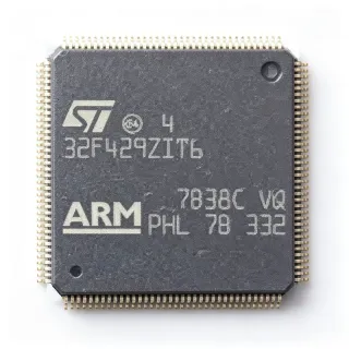
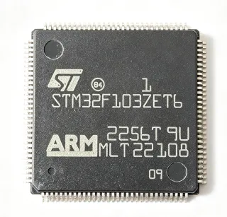
STM32L471ZGT6 - 1MB Flash 80MHz Cortex-M4 MCU | STMicroelectronics
MPN: STM32L471ZGT6 ✓ 啟用中STM32L471ZGT6 概覽
An ultra-low-power microcontroller (MCU) is a class of microprocessor that minimizes active and standby current consumption through techniques such as voltage scaling, multiple low-power operating modes, peripheral clock gating, and integrated DC-DC converters. The STM32L4 family extends this concept with the Cortex-M4 core plus DSP instructions and a single-precision floating-point unit, enabling digital signal processing alongside efficient power management. Within the broader taxonomy, the STM32L471ZGT6 sits in the hierarchy MCU -> Arm Cortex-M microcontroller -> ultra-low-power MCU -> power management IC ecosystem.
Key features include a 1.8 V to 3.6 V supply range, batch acquisition mode for ADC, multiple low-power modes (Stop, Standby, Shutdown) drawing as little as a few hundred nanoamperes with RTC retention, a built-in 12-bit 5 Msps ADC, two DAC channels, USB 2.0 Full-Speed device/host, three I2C, three SPI, three USART plus UART, two CAN 2.0B, SDMMC, and a Crypt/AES-256 hardware accelerator. The 144-pin LQFP package supports ample GPIO for industrial control panels and sensor hubs.
The STM32L471 uses a Cortex-M4 core with FPU and DSP extensions, providing 1.25 DMIPS/MHz and a CoreMark score in the hundreds, balancing DSP capability with extreme energy efficiency. The integrated LDO(Dragon) voltage regulator and switchable DC-DC buck converter allow dynamic trade-off between quiescent current and peak performance.
Typical applications include industrial sensor nodes, wearable medical monitors, smart metering, battery-powered IoT gateways, and motor control subsystems where extended battery life and deterministic real-time response are simultaneously required. The 1 MB Flash enables on-board firmware with secure bootloaders, OTA stacks, and rich protocol libraries.
When designing, always verify the supply decoupling network (1uF + 100nF + 4.7uF bulk) per ST AN4325 reference design and consider the 32 kHz LSE crystal selection for RTC accuracy. The 144-LQFP package simplifies layout but requires thermal relief for applications pushing >70% CPU duty.
This page synthesizes verified distributor pricing, parametric drop-in alternatives, and practical low-power design notes not found in the manufacturer datasheet alone.
直接替換替代品,適用於 STM32L471ZGT6 — 相同封裝,腳位對腳位相容。需重新設計 PCB 的不同封裝零件不列入。
此系列的變體
與下列產品可直接替換的同系列型號: STM32L471ZGT6 (相同外形與佔位) — 差異在於 ADC, Package, SRAM, Core Architecture, Operating Temperature Range.
STM32L471RGT6
✅ 直接替換📋 參考替代品(不在目錄中)
STM32L471VGT6
✅ 直接替換📋 參考替代品(不在目錄中)
STM32L471QGI6
✅ 直接替換📋 參考替代品(不在目錄中)
STM32L452RET6P
✅ 直接替換聯絡詢價
查看資料表 →STM32L443RCT6
✅ 直接替換聯絡詢價
查看資料表 →STM32L412RBT6P
✅ 直接替換聯絡詢價
查看資料表 →STM32L471ZGT6 最大額定值與電氣特性
| Core | Arm Cortex-M4 with FPU and DSP |
| 最大時脈頻率 | 80 MHz |
| Flash Memory | 1 MB |
| SRAM | 128 KB |
| Operating Voltage Range | 1.71 V to 3.6 V |
| 封裝 | LQFP-144 (20 x 20 mm) |
| GPIO Count | Up to 114 |
| ADC | 3 x 12-bit, 5 Msps |
| DAC | 2 x 12-bit |
| CAN | 2 x CAN 2.0B |
| USB | USB 2.0 Full-Speed device/host |
| UART/USART | 3 x USART + 2 x UART |
| SPI | 3 x SPI |
| I2C | 3 x I2C Fast-mode Plus |
| 工作溫度範圍 | -40C to +85C |
| Cryptography | AES-256 hardware accelerator |
| RoHS 狀態 | Compliant |
STM32L471ZGT6 腳位配置
| 腳位 1 | PE02 — GPIO PE2, EXTI line 2 |
| 腳位 2 | PE03 — GPIO PE3, EXTI line 3 |
| 腳位 3 | PE04 — GPIO PE4, TRACEDATA0 |
| 腳位 4 | PE05 — GPIO PE5, TRACEDATA1 |
| 腳位 5 | PE06 — GPIO PE6, WKUP3, TIM1_BKIN2 |
| 腳位 6 | VBAT — Battery supply for RTC and backup registers |
| 腳位 7 | PC13 — GPIO PC13, anti-tamper, WKUP2, RTC_OUT |
| 腳位 8 | PC14 — GPIO PC14, OSC32_IN |
| 腳位 9 | PC15 — GPIO PC15, OSC32_OUT |
| 腳位 10 | VSS — Ground |
| 腳位 11 | VDD — Digital supply voltage |
| 腳位 12 | PH00 — GPIO PH0, OSC_IN |
| 腳位 13 | PH01 — GPIO PH1, OSC_OUT |
| 腳位 14 | NRST — Reset input, active low |
| 腳位 15 | VSSA — Analog ground |
| 腳位 16 | VDDA — Analog supply voltage |
| 腳位 17 | PA00 — GPIO PA0, WKUP1, UART4_TX, TIM2_CH1 |
| 腳位 18 | PA01 — GPIO PA1, UART4_RX, TIM2_CH2, ADC_IN1 |
| 腳位 19 | PA02 — GPIO PA2, USART2_TX, TIM2_CH3, ADC_IN2 |
| 腳位 20 | PA03 — GPIO PA3, USART2_RX, TIM2_CH4, ADC_IN3 |
| 腳位 21 | VSS — Ground |
| 腳位 22 | VDD — Digital supply voltage |
| 腳位 23 | PA04 — GPIO PA4, SPI1_NSS, USART2_CK, ADC_IN4, DAC_OUT1 |
| 腳位 24 | PA05 — GPIO PA5, SPI1_SCK, ADC_IN5, DAC_OUT2 |
| 腳位 25 | PA06 — GPIO PA6, SPI1_MISO, TIM3_CH1, ADC_IN6 |
| 腳位 26 | PA07 — GPIO PA7, SPI1_MOSI, TIM3_CH2, ADC_IN7 |
| 腳位 27 | PA08 — GPIO PA8, TIM1_CH1, USART1_CK, MCO |
| 腳位 28 | PA09 — GPIO PA9, TIM1_CH2, USART1_TX |
| 腳位 29 | PA10 — GPIO PA10, TIM1_CH3, USART1_RX |
| 腳位 30 | PA11 — GPIO PA11, TIM1_CH4, USB_DM |
| 腳位 31 | PA12 — GPIO PA12, TIM1_ETR, USB_DP |
| 腳位 32 | PA13 — GPIO PA13, SWDIO, JTMS |
| 腳位 33 | VSS — Ground |
| 腳位 34 | VDD — Digital supply voltage |
| 腳位 35 | PA14 — GPIO PA14, SWCLK, JTCK |
| 腳位 36 | PA15 — GPIO PA15, JTDI, TIM2_CH1 |
| 腳位 37 | PB00 — GPIO PB0, TIM3_CH3, ADC_IN8 |
| 腳位 38 | PB01 — GPIO PB1, TIM3_CH4, ADC_IN9 |
| 腳位 39 | PB02 — GPIO PB2, BOOT1 |
| 腳位 40 | PB03 — GPIO PB3, JTDO, TIM2_CH2, SPI1_SCK |
| 腳位 41 | PB04 — GPIO PB4, JTRST, TIM3_CH1, SPI1_MISO |
| 腳位 42 | PB05 — GPIO PB5, I2C1_SMBAI, TIM3_CH2, SPI1_MOSI |
| 腳位 43 | PB06 — GPIO PB6, I2C1_SCL, USART1_TX, TIM4_CH1 |
| 腳位 44 | PB07 — GPIO PB7, I2C1_SDA, USART1_RX, TIM4_CH2 |
| 腳位 45 | BOOT0 — Boot mode selection |
| 腳位 46 | PB08 — GPIO PB8, I2C1_SCL, TIM4_CH3, SDMMC1_D4 |
| 腳位 47 | PB09 — GPIO PB9, I2C1_SDA, TIM4_CH4, SDMMC1_D5 |
| 腳位 48 | VSS — Ground |
| 腳位 49 | VDD — Digital supply voltage |
| 腳位 50 | PB10 — GPIO PB10, I2C2_SCL, USART3_TX, TIM2_CH3 |
| 腳位 51 | PB11 — GPIO PB11, I2C2_SDA, USART3_RX, TIM2_CH4 |
| 腳位 52 | PB12 — GPIO PB12, SPI2_NSS, I2S2_WS, TIM1_BKIN |
| 腳位 53 | PB13 — GPIO PB13, SPI2_SCK, I2S2_CK, USART3_CK |
| 腳位 54 | PB14 — GPIO PB14, SPI2_MISO, TIM1_CH1, SDMMC1_D0 |
| 腳位 55 | PB15 — GPIO PB15, SPI2_MOSI, TIM1_CH2, SDMMC1_D1 |
| 腳位 56 | PD00 — GPIO PD0, SPI2_NSS, CAN1_RX, TIM4_CH1 |
| 腳位 57 | PD01 — GPIO PD1, SPI2_SCK, CAN1_TX, TIM4_CH2 |
| 腳位 58 | PD02 — GPIO PD2, USART3_RX, TIM3_ETR, SDMMC1_CMD |
| 腳位 59 | PD03 — GPIO PD3, USART2_CTS, SPI2_MISO |
| 腳位 60 | PD04 — GPIO PD4, USART2_RTS, SPI2_MOSI |
| 腳位 61 | PD05 — GPIO PD5, USART2_TX |
| 腳位 62 | PD06 — GPIO PD6, USART2_RX, SDMMC1_CK |
| 腳位 63 | PD07 — GPIO PD7, USART2_CK, SDMMC1_CMD |
| 腳位 64 | VSS — Ground |
| 腳位 65 | VDD — Digital supply voltage |
| 腳位 66 | PD08 — GPIO PD8, USART3_TX, SDMMC1_D0 |
| 腳位 67 | PD09 — GPIO PD9, USART3_RX, SDMMC1_D1 |
| 腳位 68 | PD10 — GPIO PD10, USART3_CK, SDMMC1_D2 |
| 腳位 69 | PD11 — GPIO PD11, USART3_CTS, SDMMC1_D3 |
| 腳位 70 | PD12 — GPIO PD12, TIM4_CH1, USART3_RTS |
| 腳位 71 | PD13 — GPIO PD13, TIM4_CH2 |
| 腳位 72 | PD14 — GPIO PD14, TIM4_CH3, UART8_CTS |
| 腳位 73 | PD15 — GPIO PD15, TIM4_CH4, UART8_RTS |
| 腳位 74 | VSS — Ground |
| 腳位 75 | VDD — Digital supply voltage |
| 腳位 76 | PE00 — GPIO PE0, TIM4_ETR, UART8_TX |
| 腳位 77 | PE01 — GPIO PE1, UART8_RX |
| 腳位 78 | PE07 — GPIO PE7, TIM1_ETR |
| 腳位 79 | PE08 — GPIO PE8, TIM1_CH1N |
| 腳位 80 | PE09 — GPIO PE9, TIM1_CH1 |
| 腳位 81 | VSS — Ground |
| 腳位 82 | VDD — Digital supply voltage |
| 腳位 83 | PE10 — GPIO PE10, TIM1_CH2N |
| 腳位 84 | PE11 — GPIO PE11, TIM1_CH2 |
| 腳位 85 | PE12 — GPIO PE12, TIM1_CH3N, SPI1_NSS |
| 腳位 86 | PE13 — GPIO PE13, TIM1_CH3, SPI1_SCK |
| 腳位 87 | PE14 — GPIO PE14, TIM1_CH4, SPI1_MISO |
| 腳位 88 | PE15 — GPIO PE15, TIM1_BKIN, SPI1_MOSI |
| 腳位 89 | PB10 — GPIO PB10 (alt) |
| 腳位 90 | PB11 — GPIO PB11 (alt) |
| 腳位 91 | VSS — Ground |
| 腳位 92 | VDD — Digital supply voltage |
| 腳位 93 | PC00 — GPIO PC0, ADC_IN10, TIM1_CH1 |
| 腳位 94 | PC01 — GPIO PC1, ADC_IN11, TIM1_CH2 |
| 腳位 95 | PC02 — GPIO PC2, ADC_IN12, SPI2_MISO |
| 腳位 96 | PC03 — GPIO PC3, ADC_IN13, SPI2_MOSI |
| 腳位 97 | VSSA — Analog ground |
| 腳位 98 | VREF+ — ADC reference voltage high |
| 腳位 99 | VDDA — Analog supply voltage |
| 腳位 100 | VREF- — ADC reference voltage low |
| 腳位 101 | PH00 — GPIO PH0, OSC_IN |
| 腳位 102 | PH01 — GPIO PH1, OSC_OUT |
| 腳位 103 | PH02 — GPIO PH2 |
| 腳位 104 | PA08 — GPIO PA8 (alt) |
| 腳位 105 | PA09 — GPIO PA9 (alt) |
| 腳位 106 | VSS — Ground |
| 腳位 107 | VDD — Digital supply voltage |
| 腳位 108 | PA10 — GPIO PA10 (alt) |
| 腳位 109 | PA11 — GPIO PA11 (alt) |
| 腳位 110 | PA12 — GPIO PA12 (alt) |
| 腳位 111 | PA13 — GPIO PA13 (alt) |
| 腳位 112 | PA14 — GPIO PA14 (alt) |
| 腳位 113 | PA15 — GPIO PA15 (alt) |
| 腳位 114 | PC04 — GPIO PC4, ADC_IN14 |
| 腳位 115 | PC05 — GPIO PC5, ADC_IN15 |
| 腳位 116 | PB00 — GPIO PB0 (alt) |
| 腳位 117 | PB01 — GPIO PB1 (alt) |
| 腳位 118 | PB02 — GPIO PB2 (alt) |
| 腳位 119 | VSS — Ground |
| 腳位 120 | VDD — Digital supply voltage |
| 腳位 121 | PB12 — GPIO PB12 (alt) |
| 腳位 122 | PB13 — GPIO PB13 (alt) |
| 腳位 123 | PB14 — GPIO PB14 (alt) |
| 腳位 124 | PB15 — GPIO PB15 (alt) |
| 腳位 125 | PC06 — GPIO PC6, TIM3_CH1 |
| 腳位 126 | PC07 — GPIO PC7, TIM3_CH2 |
| 腳位 127 | PC08 — GPIO PC8, TIM3_CH3, SDMMC1_D0 |
| 腳位 128 | PC09 — GPIO PC9, TIM3_CH4, SDMMC1_D1 |
| 腳位 129 | PA00 — GPIO PA0 (alt) |
| 腳位 130 | PA01 — GPIO PA1 (alt) |
| 腳位 131 | VSS — Ground |
| 腳位 132 | VDD — Digital supply voltage |
| 腳位 133 | PA02 — GPIO PA2 (alt) |
| 腳位 134 | PA03 — GPIO PA3 (alt) |
| 腳位 135 | PA04 — GPIO PA4 (alt) |
| 腳位 136 | PA05 — GPIO PA5 (alt) |
| 腳位 137 | PA06 — GPIO PA6 (alt) |
| 腳位 138 | PA07 — GPIO PA7 (alt) |
| 腳位 139 | PC10 — GPIO PC10, USART3_TX, I2S3_CK |
| 腳位 140 | PC11 — GPIO PC11, USART3_RX, I2S3_SD |
| 腳位 141 | PC12 — GPIO PC12, USART3_CK, I2S3_WS |
| 腳位 142 | PD00 — GPIO PD0 (alt) |
| 腳位 143 | PD01 — GPIO PD1 (alt) |
| 腳位 144 | VSS — Ground (bottom pad exposed thermal) |
典型應用
STM32L471ZGT6 適用於 6 應用s: Industrial Sensor Hubs and IoT Gateways, Wearable Medical and Health Monitors, Smart Metering and Energy Monitoring, Low-Power Motor Control and Field-Oriented Control (FOC), Portable Consumer Devices and Battery IoT, Aerospace Telemetry and UAV Flight Controllers.
Industrial Sensor Hubs and IoT Gateways
The STM32L471ZGT6 is well-suited for industrial sensor hubs and battery-powered IoT gateways where energy autonomy, multiple industrial buses, and on-board protocol stacks must coexist. Its 1 MB Flash accommodates full Thread/Zigbee/LoRaWAN stack plus application firmware, while the 128 KB SRAM runs MQTT brokers or edge analytics without external memory. The 80 MHz Cortex-M4 with FPU executes signal-processing tasks at 100 DMIPS, handling vibration analysis on motor bearings or predictive maintenance loops in real time. Two CAN 2.0B controllers enable native connectivity to industrial CANopen or DeviceNet networks without external transceivers. According to ST datasheet, Stop2 mode at 1.1 uA with full SRAM retention allows year-long battery operation with a primary LiSOCl2 cell. Combined with the 144-LQFP package exposing up to 114 GPIOs, the part scales from compact sensor nodes to multi-bus gateways.
推薦
Wearable Medical and Health Monitors
For wearable medical monitors, the STM32L471ZGT6 offers a unique blend of DSP-grade Cortex-M4 compute with extreme energy efficiency. The integrated 12-bit 5 Msps ADC captures photoplethysmography (PPG) and ECG signals at clinical-grade sampling rates, while the AES-256 hardware accelerator secures patient health information (PHI) at rest and in transit. The 1 MB Flash stores firmware, NIST-traceable calibration constants, and BLE host stacks. Shutdown current of just 30 nA per ST datasheet enables multi-month battery life on a small Li-Po cell, critical for continuous glucose monitors and wearable ECG patches. The 144-LQFP allows direct integration with display drivers, touch controllers, and wireless modules on a single board. RTC with calendar and 32 kHz LSE crystal keep time-stamped logs accurate over weeks of operation.
推薦
Smart Metering and Energy Monitoring
The STM32L471ZGT6 is engineered for smart electricity, gas, and water metering applications where 10+ year battery life and regulatory metrology accuracy must coexist. Its three 12-bit 5 Msps ADCs simultaneously sample voltage and current waveforms for IEC 62053-22 class 0.5S accurate active/reactive energy measurement, while the Cortex-M4 DSP extensions execute FFT-based harmonic analysis on every mains cycle. Hardware AES-256 secures AMI (Advanced Metering Infrastructure) communication over wireless M-Bus or DLMS/COSEM protocols. Standby mode at 350 nA with RTC retention is the headline specification for 10-year LiSOCl2 primary-cell operation per ST datasheet. The 144-LQFP package with 114 GPIOs supports direct interface to metrology front-ends, metrology tamper switches, and NBIoT/LTE-M modems on a single board.
推薦
Low-Power Motor Control and Field-Oriented Control (FOC)
For battery-powered brushless DC (BLDC) and permanent-magnet synchronous motor (PMSM) drives, the STM32L471ZGT6 delivers Cortex-M4 + DSP compute for sensorless field-oriented control without a separate DSP chip. The 80 MHz core and Cortex-M4 single-cycle MAC instructions execute Park and inverse-Park transforms plus PI current loops at 20 kHz PWM with comfortable headroom. Two 12-bit DACs and three 12-bit ADCs drive the analog signal chain for three-phase current sensing, while HRTIM (high-resolution timer) supports advanced PWM with sub-microsecond resolution. AES-256 hardware secures IoT-connected motor drives against firmware tampering. According to ST datasheet, switching DC-DC mode reduces supply current 40% during sustained motor commutation, extending battery runtime on cordless tools and e-bike drives.
推薦
Portable Consumer Devices and Battery IoT
The STM32L471ZGT6 serves portable consumer electronics such as smart locks, GPS trackers, and wireless sensor peripherals where multi-day battery life and USB charging are first-class requirements. USB 2.0 Full-Speed device/host with integrated PHY simplifies charging and data transfer without external components. Stop2 mode at 1.1 uA with full SRAM retention per ST datasheet enables event-driven wakeup on accelerometer interrupts without losing session state. The 1 MB Flash accommodates rich Bluetooth Low Energy or proprietary 2.4 GHz protocol stacks plus secure bootloaders. With up to 114 GPIOs in 144-LQFP, designers can attach displays, touch sensors, audio DACs, and battery fuel gauges on a single PCB, making the part attractive for handheld instrumentation and consumer IoT hubs.
推薦
Aerospace Telemetry and UAV Flight Controllers
For UAV flight controllers and aerospace telemetry units, the STM32L471ZGT6 delivers aerospace-parity signal-processing compute with a hardened industrial temperature grade. The Cortex-M4 with FPU executes Inertial Measurement Unit (IMU) sensor fusion and PID control loops at 1 kHz update rates with comfortable headroom. Two CAN 2.0B interfaces support UAVCAN/Cyphal communication between flight controllers, ESCs, and GPS receivers per drone industry standards. Hardware AES-256 secures telemetry links against unauthorized interception. Stop2 mode at 1.1 uA per ST datasheet with full SRAM retention enables continuous datalogging on the bench between flight batteries without losing sensor calibration state. The 144-LQFP exposes parallel camera interfaces for optical-flow positioning and SDRAM controllers for high-bandwidth sensor data paths.
推薦
推薦產品摘要
工程參考資料,適用於 STM32L471ZGT6 — 比較、設計指引及合規資訊。
選型指南
與替代品比較
| 參數 | 本產品 | STM32L471RGT6 | STM32L471VGT6 | STM32L471QGI6 | STM32L452RET6P |
|---|---|---|---|---|---|
| Brand | STMicroelectronics | STMicroelectronics | STMicroelectronics | STMicroelectronics | STMicroelectronics |
| Package | LQFP-144 | LQFP-64 | LQFP-100 | UFBGA-132 | LQFP-64 |
| Core | Cortex-M4 + FPU | Cortex-M4 + FPU | Cortex-M4 + FPU | Cortex-M4 + FPU | Cortex-M4 + FPU |
| Flash | 1 MB | 1 MB | 1 MB | 1 MB | 256 KB |
| SRAM | 128 KB | 128 KB | 128 KB | 128 KB | 64 KB |
| Maximum Clock Frequency | 80 MHz | 80 MHz | 80 MHz | 80 MHz | 80 MHz |
| GPIO Count | 114 | 51 | 82 | 109 | 51 |
| Operating Voltage | 1.71 V to 3.6 V | 1.71 V to 3.6 V | 1.71 V to 3.6 V | 1.71 V to 3.6 V | 1.71 V to 3.6 V |
| CAN Controllers | 2 | 2 | 2 | 2 | 1 |
| AES-256 Hardware | Yes | Yes | Yes | Yes | Yes |
主要差異化特點
- Highest pin count in STM32L471 family (對比STM32L471RGT6)
- 1 MB Flash with FPU + DSP (對比STM32L452RET6P)
- Full hardware AES-256 + 32 KB SRAM2a (對比STM32L443RCT6)
設計說明
The STM32L471ZGT6 ships with both LDO and integrated DC-DC buck converter (PWR_CR register PWR_LDO_SCALE bit). For battery applications demanding the lowest Stop2 current (1.1 uA per ST datasheet), select the LDO mode and disable the DC-DC converter. Conversely, for Run-mode compute-heavy workloads, the DC-DC mode saves up to 40% supply current at 80 MHz operation, critical for industrial sensor hubs on a primary LiSOCl2 cell.
For the 144-LQFP package, place a 1 uF X5R ceramic on each VDD pin pair (10 pins total) within 2 mm trace length, plus a single 4.7 uF bulk capacitor on the VDDA pin. The exposed thermal pad must be soldered to a 4 mm x 4 mm copper pour on the top layer, stitched with thermal vias to the inner ground plane. Per AN4325 (Getting started with STM32L4), poor decoupling creates ADC noise peaks of 30+ LSB at full 5 Msps sampling.
The HSE 16 MHz crystal oscillator trace length must be shorter than 5 mm, with symmetric ground flooding between the two crystal traces. Add a 5.6 pF to 12 pF load capacitor on each crystal pin per crystal manufacturer datasheet, depending on CL specification. For RTC accuracy, choose a 32.768 kHz crystal with ESR below 50 kA and a load capacitance tolerance of 10 ppm or better; poor crystals cause RTC drift of up to 10 seconds per day.
Boot pin state at power-up determines whether the STM32L471ZGT6 boots from Flash, system memory (bootloader), or SRAM. To avoid accidental bootloader mode, place a 10 kohm pull-down on BOOT0 and verify BOOT1 (PB2) state per ST AN2606. Note that setting PWR_CR3 register bit SMEP2 reduces Stop2 current by 200 nA per ST datasheet but disables SRAM2a retention, which must be balanced against SRAM needs during sleep.
合規資訊
RoHS and REACH compliant per ST product page declaration. Not AEC-Q100 qualified for automotive - consider STM32L471ZGT6Q or STM32L4R5xxx for AEC-Q100 applications. Halogen-free per ST REACH presentation. Conflict minerals compliant per ST supplier policy.