浪涌保护器
产品(130)

0402ESDA-05N - 5V Bidirectional Polymer ESD Suppressor | BORN
The BORN 0402ESDA-05N is a bidirectional polymer ESD suppressor with a 5V working voltage, 50V clamp-side breakdown capability, ultra-low 1.5 pF line capacitance, and 1 nA leakage current, housed in a 2-terminal 0402 (1005 metric) surface-mount package. It is qualified to suppress electrostatic discharge events per IEC 61000-4-2 and operates over a -40C to +85C industrial temperature range. A polymer ESD suppressor is a type of transient voltage suppression device within the broader family of TVS diodes and circuit protection components. Unlike silicon avalanche TVS diodes, polymer suppressors use a conductive polymer material that switches from a high-impedance state to a low-impedance state within nanoseconds when an ESD transient exceeds its trigger threshold, shunting the surge energy away from the protected IC. This technology enables extremely low parasitic capacitance, which is the defining parameter for high-speed data line protection. Key features of the 0402ESDA-05N include its 1.5 pF typical capacitance, which minimizes signal insertion loss on USB 2.0, HDMI, and other multi-gigabit interfaces; its bidirectional 5V standoff rating suited to both single-ended and symmetric data lines; and its nanosecond response time to IEC 61000-4-2 contact and air discharges. The 1 nA reverse leakage keeps standby power consumption negligible in battery-powered designs. The polymer construction provides no DC clamping action under normal operating conditions, so the line sees essentially the suppressor capacitance only. During an ESD event, the device transitions to a conductive state and recovers automatically after the transient passes, requiring no replacement or reset. The compact 0402 footprint allows placement directly adjacent to the connector pins. Typical applications include high-speed data port protection on smartphones, tablets, and set-top boxes; ESD protection for USB, HDMI, and antenna lines in consumer electronics; and protection of sensitive RF front-ends where capacitance must stay below 2 pF. Design tip: place the suppressor as close to the connector as possible with minimal stub length, following the zero-stub pad guidance common to polymer ESD devices, so the transient is clamped before it propagates down the trace. This page synthesizes distributor pricing, drop-in alternatives, and practical design notes not found in the manufacturer datasheet.

1.5KE11CA - 1500W Bidirectional TVS, 9.4V VRWM | Littelfuse
The Littelfuse 1.5KE11CA is a 1500W bidirectional axial-leaded Transient Voltage Suppressor (TVS) diode designed to clamp voltage transients induced by lightning, inductive load switching, and ESD events on sensitive electronic equipment. According to the Littelfuse datasheet, it features a Reverse Working Standoff Voltage (VRWM) of 9.4V, a Breakdown Voltage range of 10.5V to 11.6V, a maximum clamping voltage of 15.6V at 97.4A peak pulse current, and is housed in a DO-201 through-hole axial package. A TVS diode is a solid-state avalanche device engineered to shunt large transient currents away from downstream circuitry in microseconds, providing far faster response than MOVs or PTC fuses. TVS diodes sit at the bottom of the protection hierarchy as discrete semiconductors, fall under the surge-protector family, and serve as the first-line defense on DC power rails, signal lines, and automotive bus networks where predictable clamping behavior is mandatory. Key differentiating specifications include 1500W peak pulse power dissipation at a 10/1000 microsecond waveform, a peak pulse current (IPPM) of 97.4A, glass-passivated chip junction construction for long-term reliability, low Zener impedance, and a maximum clamping voltage of 15.6V that keeps downstream 12V logic rails well within their absolute-maximum ratings during surge events. The bidirectional (CA suffix) variant conducts transients of either polarity, eliminating orientation errors during PCB assembly. Architecturally, the 1.5KE11CA is a silicon PN-junction avalanche suppressor with a glass-passivated surface that suppresses leakage and stabilizes breakdown characteristics across the -55C to +175C operating range. The avalanche breakdown mechanism provides sub-microsecond response, ensuring that fast-rise transients such as those defined by IEC 61000-4-2 are clamped before sensitive ICs see the overvoltage. Typical applications include 12V automotive load-dump protection per ISO 7637-2, industrial PLC 24V rail transient suppression, telecom -48V battery backplane protection, USB and HDMI port ESD/lightning protection on consumer devices, and protection of SMPS auxiliary windings from flyback spikes. The wide standoff-voltage range and 1500W rating also suit PoE PSE input protection. When designing with this part, derate surge power for temperatures above 75C using the derating curve in the datasheet, ensure lead bend radius exceeds 1.5mm to avoid axial-package cracking, and place the TVS within 50mm of the protected connector for maximum effectiveness. For multi-stage protection, pair the 1.5KE11CA with an upstream GDT or PTC to coordinate energy dissipation. This page synthesizes current distributor pricing, drop-in cross-brand equivalents, parametric comparison tables, and practical design notes not found in the manufacturer datasheet alone - giving the engineer a one-stop reference for sourcing and qualifying the 1.5KE11CA in new or existing designs.
1.5KE11CA-B - 1500W Bi-Directional TVS Diode 9.4V | Littelfuse
The Littelfuse 1.5KE11CA-B is a 1500 W axial-leaded bidirectional Transient Voltage Suppressor (TVS) diode rated at 9.4 V working standoff voltage (VRWM), 10.5 V minimum breakdown voltage, and 15.6 V maximum clamping voltage at 97.4 A peak pulse current, housed in a DO-201 (DO-27) through-hole axial package. It is designed to clamp fast transient overvoltages such as those induced by lightning, inductive load switching, and ESD, protecting downstream sensitive electronics. A TVS diode (Transient Voltage Suppressor) is a semiconductor protection device belonging to the surge protector / discrete semiconductor family. Under normal operation it presents a high-impedance path; when a transient exceeds its breakdown voltage, it avalanches into a low-impedance state within picoseconds, shunting surge energy away from protected circuits. TVS diodes sit hierarchically under discrete semiconductors -> diodes -> surge protectors, and are commonly used alongside MOVs, gas discharge tubes, and PTC resettable fuses in multi-stage protection networks. The bidirectional ('CA') construction means a single device clamps both positive and negative transients, making it ideal for AC lines and differential signal interfaces. Key specifications include 1500 W peak pulse power (10/1000 µs waveform), 97.4 A peak pulse current (IPP), <1 ps typical response time, low clamping factor (15.6 V VC / 9.4 V VRWM = 1.66), and an operating temperature range that supports industrial environments. The 5 % voltage tolerance ('A' suffix) and bidirectional polarity ('C') make the 1.5KE11CA-B particularly suited for protecting 12 V system rails, RS-485 interfaces, and telecom line cards where induced surges from outdoor cabling are common. The 1.5KE11CA-B uses a silicon PN-junction avalanche structure manufactured in a glass-passivated die, packaged in a transfer-molded DO-201 body with tin-plated axial leads for wave or hand soldering. Its robust construction supports IEC 61000-4-2 (ESD) and IEC 61000-4-5 (surge) immunity testing when properly designed into the protection network. Typical applications include 12 V automotive load-dump suppression, telecommunications line-card secondary protection, industrial 24 V PLC and sensor protection, and consumer electronics AC/DC adapter input protection. Designers should place the TVS as close to the connector or transient entry point as possible, with short, wide PCB traces to minimize parasitic inductance. Design tip: combine the 1.5KE11CA-B with a PTC resettable fuse or series resistor upstream to limit sustained fault current and extend device lifetime under repeated surge events. This page synthesizes distributor pricing, drop-in equivalents from multiple brands, and practical protection-design guidance not consolidated on any single manufacturer page.
1.5KE16ARL4G - 1500W 16V Unidirectional TVS | onsemi
The onsemi 1.5KE16ARL4G is a 1500 W axial-leaded unidirectional Transient Voltage Suppressor (TVS) diode in the Surmetic DO-201AA package, designed to clamp high-energy transients and protect voltage-sensitive downstream components. The part delivers a working standoff of 13.6 V, a minimum breakdown of 15.2 V, and a maximum clamping voltage of 22.5 V at the rated 67 A peak pulse current (Ipp) per the 10/1000 µs waveform. A Transient Voltage Suppressor (TVS) is a specialized clamping diode that operates in avalanche breakdown when the line experiences a fast over-voltage event such as an ESD pulse, inductive load kickback, or lightning-induced surge. TVS diodes sit at the front of the protection topology, upstream of bulk protection (fuses, PTCs) and downstream of the exposed connector; their job is to divert surge current away from sensitive ICs within microseconds. The 1.5KE family is the workhorse 1500 W industrial/automotive grade series defined by JEDEC register DO-201AA axial outlines. Key features of the 1.5KE16ARL4G include 1500 W peak pulse power (10/1000 µs waveform), 67 A peak pulse current (Ipp), unidirectional polarity, a typical clamping voltage of 22.5 V at Ipp, low Zener impedance in breakdown, fast response time (sub-nanosecond), and a maximum clamping factor that ensures the protected downstream rail stays within its absolute-maximum rating. The Surmetic axial package is a through-hole DO-201AA body with robust leads suitable for wave-soldering and high-vibration environments. Technically, the 1.5KE16ARL4G uses a large-junction silicon die designed for non-repetitive high-energy avalanche. Peak pulse power is specified for a 10/1000 µs exponential waveform per the industry-standard TVS test method; steady-state power dissipation is rated at 5 W (with appropriate lead length derating). Reverse leakage at standoff is in the µA range, allowing the part to remain in-circuit without measurable quiescent loss. Typical applications include DC power-line protection on 12 V industrial bus rails, automotive 12 V load-dump protection, secondary protection behind a primary TVS or PTC on long signal lines, protection of telecom line drivers, and suppression of inductive kickback from relays, solenoids, and motor windings. It is also widely used in switch-mode power supply (SMPS) output rectification and snubbing. When designing with this part, derate peak pulse power for shorter pulses (the 8/20 µs waveform allows higher Ipp) and ensure lead length matches the datasheet's thermal derating curve. Avoid continuous operation in breakdown - this part is intended for transient clamping only, not as a voltage regulator.
1.5KE18AG - 18V 1500W Unidirectional TVS | onsemi
The onsemi 1.5KE18AG is a 1500 W unidirectional Mosorb Zener Transient Voltage Suppressor (TVS) in an axial-leaded through-hole package, designed to protect voltage-sensitive components from high-voltage, high-energy transients. The "1.5KE" series defines a family of glass-passivated-junction transient voltage suppressors widely used as circuit-protection devices. A TVS diode is a solid-state silicon device that clamps an overvoltage event by avalanche breakdown, shunting transient energy away from downstream circuitry. Within the broader protection hierarchy, TVS diodes sit alongside metal-oxide varistors (MOVs) and gas discharge tubes as fast-response (< 1 ns) suppressors, prized over fuses because they self-recover after the transient has decayed. Key features of the 1.5KE18AG include a working standoff voltage of 15.3 V, a maximum clamping voltage of 25.2 V at 59.5 A peak pulse current, and a peak pulse power rating of 1500 W for an 8/20 us waveform (per IEC 61000-4-5). The device offers unidirectional polarity, a glass-passivated die for stability, and a Surmetic axial package with operating junction temperature up to 175 C. The 1.5KE18AG uses an avalanche-mode silicon-junction Zener die, where the junction is glass-passivated for long-term stability and moisture resistance. Its low Zener impedance and fast response time allow it to clamp transient events from ESD, inductive load kickback, and lightning-induced surges within nanoseconds. Typical applications include protection of 12 V and 15 V dc power rails, automotive ECU inputs, industrial PLC I/O lines, telecom -48 V system protection, and USB/HDMI interface guarding on consumer equipment. When selecting layout, mount the 1.5KE18AG as close as possible to the protected connector or IC pin and minimize lead length to reduce parasitic inductance, which otherwise degrades clamping effectiveness at high dv/dt. This page synthesizes distributor pricing, drop-in alternatives, and practical design notes not found in the manufacturer datasheet, giving engineers a single anchor for board-level protection decisions.

1.5SMC8.2A-E3/9AT - 1500W 8.2V Uni-Dir TVS | Vishay
The Vishay 1.5SMC8.2A-E3/9AT is a 1500W peak-pulse-power unidirectional TRANSZORB transient voltage suppressor (TVS) diode rated at a 8.2V working standoff voltage, packaged in the industry-standard DO-214AB (SMCJ) surface-mount outline. It is engineered to clamp 12.1V at a peak pulse current of 124A (10/1000 µs waveform) and protect downstream electronics from induced lightning, load-dump, and ESD transients on DC rails. A TVS diode (Transient Voltage Suppressor) is a clamping semiconductor that operates in avalanche breakdown when the voltage across it exceeds a defined threshold. It belongs to the protective-component hierarchy: TVS diode → ESD/surge protector → discrete semiconductor → circuit protection device. Under normal operation the part presents a high-impedance path; when a transient pushes the line above its breakdown voltage (8.2V nominal / 7.02V reverse standoff), it conducts in nanoseconds and shunts the surge energy to ground, holding the protected rail to a safe clamping voltage. Key specifications include a 1500W peak pulse power dissipation on a 10/1000 µs waveform, 124A peak pulse current (Ipp), 12.1V maximum clamping voltage at Ipp, and a glass-passivated chip junction that improves long-term reliability under repetitive surge events. The TRANSZORB series uses a low-profile DO-214AB package suitable for automated placement and offers uni-directional (suffix A) polarity. Architecturally, the device is a silicon avalanche junction that has been glass-passivivated for environmental stability and given a low-inductance, large-area die bond to handle the 1500W transient. The flip-chip-style construction minimizes lead inductance so the clamping response remains sub-nanosecond, preserving the protected IC's input stage during fast-edge ESD events. Typical applications include 12V automotive load-dump protection, industrial 24V bus transient suppression, USB Type-C VBUS line protection, and telecom port protection against secondary lightning surges. Any low-voltage DC rail driving sensitive CMOS logic, microcontrollers, or RF transceivers in harsh EMI environments can leverage this part. When designing with this device, observe the derating curve over temperature - peak pulse power falls linearly from 1500W at 25°C toward zero at the maximum TJ. Place the TVS as close as possible to the connector entry point and keep the trace to ground short and wide to minimize parasitic inductance that would otherwise let voltage overshoot above the 12.1V clamp rating. This page synthesizes distributor pricing, parametric drop-in alternatives sourced from cross-reference tools, and applied design guidance beyond what is published in the manufacturer's datasheet alone.
1.5SMCJ54C - 1500W TVS Diode 54V Bidirectional SMC | Diotec
The Diotec 1.5SMCJ54C is a 1500 W peak-pulse surface-mount transient voltage suppressor (TVS) diode in a bidirectional configuration with a stand-off working voltage of 54 V, housed in a DO-214AB (SMC) plastic package. It is engineered to clamp fast transient events such as ESD, EFT, and lightning-induced surges on 48 V telecom, industrial-bus, and DC power-distribution lines, providing a maximum clamping voltage of approximately 87.1 V at the rated 1500 W peak pulse power (10/1000 µs waveform). What is a TVS diode? A transient voltage suppressor is a discrete semiconductor protection device that responds to over-voltage events in the nanosecond time domain by avalanching into a low-impedance state, shunting surge current away from sensitive downstream circuitry. TVS diodes sit within the broader hierarchy of discrete semiconductors (diodes -> protection devices -> TVS) and are commonly specified alongside metal-oxide varistors (MOVs) and gas discharge tubes (GDTs) as a second-tier clamp after primary over-current protection. The "C" suffix indicates bidirectional operation, meaning a single part protects both polarities of an AC or DC-coupled bus without orientation sensitivity. Key features include a minimum breakdown voltage of 60.0 V and a maximum breakdown of 66.0 V at 1 mA, a maximum reverse leakage of 5 µA at the rated stand-off, a peak forward surge rating suited for the SMC footprint, and a glass-passivated junction rated for 150 °C junction temperature. The low-profile DO-214AB (SMC) body has Underwriters Laboratory Flammability Classification 94V-0 and supports 260 °C / 10 s high-temperature soldering for lead-free reflow compatibility. Typical applications include 48 V PoE protection, telecom line-card secondary protection, industrial 24/48 V DC bus transient suppression, photovoltaic inverter input clamping, and DC motor drive H-bridge protection. Designers also use 1.5SMCJ54C series parts as secondary protection after a primary GDT or PTC to limit let-through energy. When designing with this device, verify that the chosen working voltage (Vrwm = 54 V) sits above the maximum continuous operating voltage of the protected bus, and confirm that the peak-pulse power derating curve at the expected surge duration does not exceed 1500 W. Bidirectional parts require no orientation marking, simplifying PCB layout and rework.
1SMC12AT3G - 12V 1500W TVS Diode SMC | Littelfuse
The Littelfuse 1SMC12AT3G is a 12 V unidirectional Zener Transient Voltage Suppressor (TVS) diode rated at 1500 W peak pulse power, packaged in a surface-mount DO-214AB (SMC) case. It clamps to 19.9 V at 75.3 A of peak pulse current and is engineered to protect voltage-sensitive components from high-voltage, high-energy transients such as those produced by inductive load switching, lightning-induced surges, and electrostatic discharge events on data and signal lines. A TVS diode is a specialized semiconductor protection device that operates in avalanche breakdown under reverse-bias stress, diverting transient energy away from downstream circuitry within sub-microsecond response times. Sitting at the bottom of the protection hierarchy alongside MOVs, gas discharge tubes, and polymer ESD suppressors, TVS diodes combine fast response, well-defined clamping voltage, and repeatable surge handling - making them the preferred choice for secondary-side protection on DC power rails and signal interfaces. Key features include a 12 V working standoff voltage, 19.9 V maximum clamping voltage at Ipp = 75.3 A, an excellent clamping ratio, low Zener impedance under breakdown, leakage below 5 uA above 10 V, and a peak forward surge rating suitable for industrial transient environments. The SMC (DO-214AB) molded plastic package offers a void-free thermosetting construction compatible with industry-standard reflow profiles. Internally the 1SMC12AT3G is a silicon PN-junction Zener structure with a large die optimized for uniform avalanche breakdown across the full junction area. This avoids localized hot spots during high-current 8/20 us or 10/1000 us surge pulses, which is why the part reliably dissipates 1500 W peak power for short durations. Typical applications are DC power rail protection (12 V systems), automotive load-dump transient suppression, industrial control I/O protection, USB and CAN bus line protection, and protection of MOSFET gate drivers and telecom equipment from induced surge events. The unidirectional polarity suits circuits where a single voltage polarity is present. When designing with this part, ensure PCB pad geometry follows the SMC land pattern (DO-214AB), use wide copper traces to the cathode and anode pads to handle peak surge current, and pair the TVS with a typical upstream fuse or PTC for sustained over-voltage or over-current faults.
1SMC24AT3G - 1500W TVS Diode, 38.9V Clamp | Littelfuse
The Littelfuse 1SMC24AT3G is a 1500 W peak-power unidirectional Zener transient-voltage suppressor in an SMC surface-mount package. Its verified clamp voltage is 38.9 V, its peak pulse current is 38.6 A, and its surface-mount construction supports compact protection layouts. The device is intended to protect voltage-sensitive components from high-voltage, high-energy transients. A TVS diode, also called a transient-voltage suppressor, is a discrete semiconductor device that diverts surge energy through a deliberately nonlinear voltage-current characteristic. In the broader protection hierarchy, a TVS diode sits above or alongside fuse, MOV, and ESD-protection devices: it provides fast response and high surge capability while limiting the voltage reaching the protected circuit. The 1SMC24AT3G is used when a robust, high-energy surface-mount suppressor is preferred over lower-energy signal-line protection. The key verified specifications are its 1500 W peak-power rating, 38.9 V clamp voltage, and 38.6 A peak pulse current. Littelfuse describes the SMC series as having excellent clamping capability, high surge capability, low Zener impedance, and fast response time. Its SMC package is suitable for automated PCB assembly and is intended for communication systems, automotive equipment, numerical controls, process controls, medical equipment, and business machines. The device is unidirectional, so its cathode and anode orientation must be respected during layout and assembly. The clamp specification is a protection-related voltage limit under surge conditions, not the normal operating voltage of the protected rail. Designers should verify that the protected circuit remains within its absolute maximum voltage during the selected surge waveform. Because the available verified data does not provide the complete manufacturer parameter table, values such as reverse stand-off voltage, breakdown voltage, and thermal resistance are marked for data completion rather than guessed. Typical implementation places the TVS diode close to the connector, power-entry point, or exposed interface conductor so surge current is diverted through a short, low-inductance path. The PCB copper area must be large enough to carry the transient current, while the protected trace and return path should remain physically separated from the surge-current loop. This is especially important in communication, automotive, industrial-control, and medical systems where an external transient can propagate through a cable or chassis connection. This page synthesizes the verified distributor listing, manufacturer product description, cross-reference results, package information, and practical protection-layout guidance. It distinguishes confirmed values from unavailable electrical details so engineers can make a safe sourcing decision and cross-check the manufacturer datasheet before release to production.

AQ15-02HTG - 15V 500W 2-Channel TVS Diode Array | Littelfuse
The Littelfuse AQ15-02HTG is a 2-channel, 500 W transient voltage suppressor (TVS) diode array designed to protect sensitive electronics from electrostatic discharge (ESD), electrical fast transients (EFT), and lightning-induced surges. Housed in a compact SOT-23-3 surface-mount package, it provides a working voltage of 15 V, a clamping voltage of 30 V at 15 A (8/20 µs), and a peak pulse power rating of 500 W (8/20 µs). A TVS diode array is a class of discrete semiconductor protection device that uses avalanche-breakdown junctions to clamp transient overvoltages to safe levels in microseconds. TVS arrays sit in the protection-component hierarchy between simple Zener clamps and multi-stage gas-discharge or polymer suppressors, and they belong to the broader category of circuit-protection semiconductors. By integrating two steering diodes and a central TVS die in a single 3-pin package, the AQxx-02HTG series provides differential or single-ended protection on data lines and power rails without requiring multiple discrete components. Key features include ±30 kV ESD protection per IEC 61000-4-2 (contact and air discharge), ultra-low capacitance of 85 pF suitable for high-speed interfaces, low clamping voltage of 30 V at 15 A peak pulse current, and a low leakage current of 1 µA at the working voltage. The SOT-23-3 package is footprint-compatible with industry-standard 3-pin SOT-23 outlines, enabling drop-in placement on existing PCB layouts. The AQ15-02HTG uses an avalanche-junction TVS structure combined with low-capacitance steering diodes, achieving sub-nanosecond turn-on time. This architecture absorbs repetitive strikes without performance degradation, making it ideal for industrial and automotive environments exposed to frequent ESD events. The 85 pF line capacitance is acceptable for CAN, RS-485, and general-purpose I/O protection but should be evaluated for USB 2.0 high-speed data lines where lower capacitance is preferred. Typical applications include industrial CAN bus protection, RS-485 transceiver protection, automotive ECU I/O protection, sensor interface protection, factory automation I/O, and consumer electronics ESD protection on USB and HDMI ports. The AQxx-02HTG series is AEC-Q101 qualified for automotive use. When designing with this device, place the AQ15-02HTG as close as possible to the connector or ESD entry point, keep the trace between the protected IC and the TVS short, and provide a low-impedance ground return to the chassis or earth ground. Avoid routing protected traces beneath the device to minimize parasitic coupling. This page synthesizes distributor pricing, drop-in alternatives, and practical layout guidance not aggregated in the manufacturer datasheet, giving engineers a single reference for component selection, BOM risk mitigation, and PCB design.

CDDFN2-T3V3SC - 3.3V Bidirectional TVS Diode, DFN-2 | Bourns
The Bourns CDDFN2-T3V3SC is a 3.3 V bidirectional surface-mount Transient Voltage Suppressor (TVS) housed in a sub-miniature DFN-2 (0402-size, 1.0 mm x 0.6 mm x 0.5 mm) package. It delivers ESD, EFT and surge protection for external ports of portable electronic devices and provides a typical clamping voltage of 9 V at 42 A peak pulse current (8/20 us waveform). The device is designed for direct PCB mounting on high-density I/O lines where a board area is impossible. A TVS diode is a semiconductor clamp that diverts over-voltage energy away from sensitive downstream circuitry. When the line voltage exceeds the device's breakdown threshold, the TVS enters avalanche breakdown within nanoseconds and shunts the transient current to ground, limiting the peak voltage seen by the protected IC. TVS diodes sit at the first tier of a protection scheme (next to gas-discharge tubes and PTC fuses) and are the fastest-responding element, making them ideal for suppressing ESD (electrostatic discharge) and EFT (electrical fast transient) events at connector pins. As a discrete protection component, the TVS diode belongs to the broader family of surge protection devices used in transient voltage suppression. Key specifications include a 3.3 V working voltage (VRWM), 9 V typical clamping voltage (VC) at 42 A Ipp (8/20 us), bidirectional polarity, and a sub-nanosecond response time. The DFN-2 (0402-style) package occupies 0.6 mm footprint area per side and operates across -55 C to +150 C. It is qualified to IEC 61000-4-2 (ESD) air-discharge ratings typical of the family, and the device is RoHS compliant and lead-free. The CDDFN2-T3V3SC uses a silicon avalanche junction in a bidirectional configuration, meaning a single device protects both polarities of an AC or differential data line. The 8/20 us surge waveform rating indicates the device can survive indirect lightning-induced surges and inductive load switching transients without degradation. Typical applications include USB 2.0/3.0 data line protection, HDMI/MIPI/MDDI interfaces, SIM card protection, headset/microphone audio jacks, portable set buttons, and any 3.3 V logic rail exposed to user contact. The DFN-2 footprint makes it especially suitable for compact handheld and wearable designs where every millimeter of PCB space counts. When designing with the CDDFN2-T3V3SC, ensure the protected signal line does not exceed the 3.3 V working voltage in normal operation, place the device as close as physically possible to the connector pin, and provide a low-impedance ground return directly beneath the package thermal pad. The device's low capacitance makes it compatible with high-speed data lines, but always verify the total channel capacitance against the interface specification.
CDDFN2-T5V0SC - 5V Bidirectional TVS Diode, 9.5V Clamp | Bourns
The Bourns CDDFN2-T5V0SC is a bidirectional surface-mount Transient Voltage Suppressor (TVS) diode rated at 5 V working voltage with a 9.5 V clamping voltage at 18 A peak pulse current (8/20 µs waveform), housed in a miniature 2-pin DFN (1.0 × 0.6 mm) package. It is engineered to absorb ESD, EFT, and surge transients on external I/O ports of portable and handheld electronics, and integrates a steering diode network for clean bidirectional clamping from either polarity. A Transient Voltage Suppressor (TVS) diode is a clamping semiconductor device designed to limit transient overvoltages by avalanching into a low-impedance state when its breakdown voltage is exceeded. Within the power management hierarchy, TVS diodes sit alongside ESD protection arrays and varistors as the first line of defense for sensitive downstream ICs, providing sub-nanosecond response and a defined non-linear V-I curve. Bidirectional TVS parts such as the CDDFN2-T5V0SC are particularly suited to AC-coupled signal lines and differential data buses where polarity can reverse. The CDDFN2-T5V0SC delivers 18 A peak pulse handling on the 8/20 µs surge waveform and is rated to absorb ESD strikes per IEC 61000-4-2 at both contact and air discharge levels. Its ultra-small 1.0 × 0.6 mm DFN footprint allows placement immediately at the connector, minimizing parasitic loop area and improving coupling efficiency into the suppressor. Low clamping factor and low dynamic resistance keep the residual voltage seen by downstream ICs well below their absolute-maximum ratings. Internally the device uses a Zener-based avalanche junction combined with a steering-diode bridge, giving symmetric positive and negative clamping. The low leakage at 5 V bias preserves battery life in always-connected portable designs, while the wide operating temperature range supports industrial and outdoor deployments. The leadless DFN-2 package offers a low-inductance current path that outperforms leaded alternatives such as SOD-123 at multi-kilovolt ESD. Typical applications include USB Type-C data line protection on smartphones, tablets, and laptops, HDMI/MIPI/LVDS interface protection on display panels, antenna port ESD protection on cellular and Wi-Fi modules, headset audio jack protection, and portable medical handheld devices. The wide surge rating also covers industrial sensor interfaces and IoT edge nodes that may be exposed to EFT or lightning-induced surges on long cable harnesses. Place the CDDFN2-T5V0SC as close as physically possible to the external connector pin, with a short, direct ground return to the chassis or board ground pour. Keep the trace between the protected line and the device under 2 mm to maximize ESD suppression, and avoid routing any sensitive analog signal traces underneath the pad to prevent coupling of residual transients. This page synthesizes distributor pricing tiers, verified drop-in alternatives, and PCB-layout guidance that go beyond what is shown on the Bourns datasheet, giving engineers a single source for selection, sourcing, and design-in.
CDSOT23-SM712 - 7V/12V Asym RS-485 TVS Array 400W | Bourns
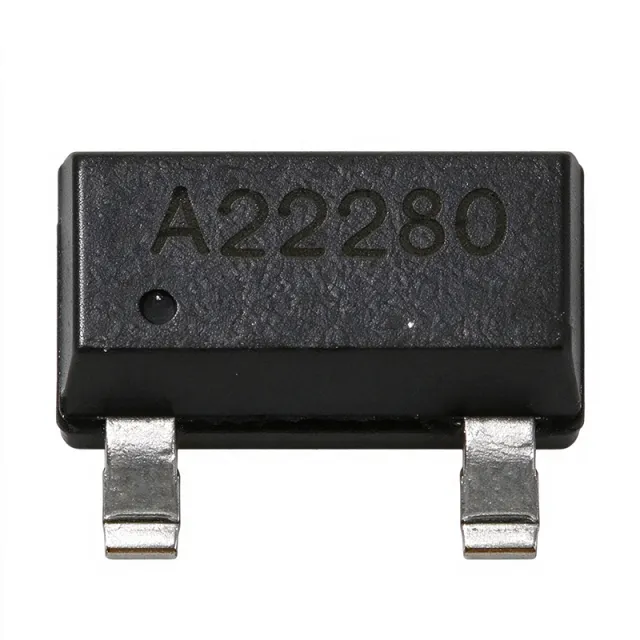
The Bourns CDSOT23-SM712 is a surface-mount transient voltage suppressor (TVS) diode array housed in a SOT-23-3 package, providing 400 W peak pulse power per line for asymmetrical protection of RS-485/RS-422 data lines. The device integrates two TVS diodes with a Working Peak Reverse Voltage of 7 V (positive side) and 12 V (negative side), Minimum Breakdown Voltage of 7.5 V and 13.3 V respectively, and maximum clamping voltages of 14 V and 26 V at 17 A (8/20 us waveform). The asymmetry is intentional - it tracks the wider negative common-mode range of RS-485 transceivers that must tolerate -7 V to +12 V. A TVS diode array is a specialized class of transient voltage suppressor that integrates multiple steering/clamps in one package to protect differential data ports. The CDSOT23-SM712 belongs to the diode array > TVS array > ESD protection IC > circuit protection hierarchy. These arrays are essential companions to bus transceivers (RS-485, CAN, Profibus), where the transceiver's own absolute-maximum ratings are routinely violated by ESD, EFT, or surge events on the bus cable. Key features include IEC 61000-4-2 (ESD) protection to +/-30 kV air and +/-30 kV contact, IEC 61000-4-4 (EFT) to 40 A (5/50 ns), and IEC 61000-4-5 (surge) to 17 A (8/20 us). The device provides low capacitance (per datasheet typical application) to preserve signal integrity at high data rates, and the SOT-23-3 footprint is the industry-standard pinout for SM712-style arrays. A low leakage current at 5 V maximises battery life in quiescent-mode industrial nodes. The CDSOT23-SM712 uses an asymmetric avalanche-breakdown architecture: the 7 V TVS clamps positive transients on each data line relative to ground, while the 12 V TVS clamps the larger negative excursions permitted by RS-485. This dual-window topology is more efficient than two identical TVS diodes, because a single 12 V symmetric array would clip legitimate -7 V bus signalling, while a 7 V symmetric array would not survive the -25 V cable discharge that the RS-485 standard tolerates. The Bourns design matches the SM712 reference footprint exactly, so engineers can swap between vendors (Bourns, ST, NXP, MSKSEMI, YINT) without PCB rework. Typical applications include RS-485/RS-422 fieldbus nodes in industrial automation, Profibus and Modbus links, CAN bus nodes in heavy machinery and EV charging, HVAC controllers, building automation, smart-meter communication ports, and any line-driver exposed to ESD during cable mating or lightning-induced surge on long outdoor runs. The asymmetrical window is also useful for CAN-H and CAN-L protection where one rail must withstand -12 V cross-wiring faults. When designing with this device, place the CDSOT23-SM712 within 10 mm of the bus connector and keep the ground return path short and wide. Do not rely on the TVS alone for surge survival above 17 A - upstream PTCs or PTC+fuse combinations may be required to meet IEC 61000-4-5 level 4. The SOT-23-3 pad pattern is identical to industry-standard SOT-23, allowing use of standard land pattern footprints. This page synthesizes distributor pricing, drop-in alternatives, and practical PCB layout notes not found in the manufacturer datasheet alone - including a same-package alternative table engineers can use when second-sourcing for supply-chain resilience.
CDSOT23-T24CAN-Q - 24V CAN Bus TVS, 40V Clamp, AEC-Q101 | Bourns
The Bourns CDSOT23-T24CAN-Q is a dual bidirectional TVS diode array for CAN bus protection, offering a 40 V clamping voltage, 8 A (8/20 us) peak pulse current, and a minimum breakdown voltage of 26.2 V, housed in a 3-pin SOT-23 (SOT-23-3) surface-mount package. It is AEC-Q101 qualified for automotive applications. A TVS (Transient Voltage Suppressor) diode is a circuit-protection semiconductor that clamps transient overvoltage events, such as electrostatic discharge (ESD) and surge transients, by avalanche breakdown before they can damage sensitive transceiver circuitry. Within the protection hierarchy, TVS diode arrays sit at the board level of a layered protection strategy, complementing chip-level protection integrated inside the CAN transceiver itself. Arrays like this one integrate two TVS elements in a single package so that both lines of a differential bus are protected by one component. Key features include the dual bidirectional topology purpose-built for CANH and CANL differential lines, a minimum breakdown voltage of 26.2 V that guarantees the device will not conduct during a 24 VDC power-cross miswiring event, and a 40 V clamping voltage at the 8 A (8/20 us) surge level. The AEC-Q101 qualification ensures reliability under automotive stress conditions. The device uses avalanche breakdown diode technology with a low-clamping, fast-response characteristic. Because the protection elements are bidirectional, they clamp negative transients symmetrically on both CAN lines, protecting the transceiver differential I/O against ISO 7637-style and IEC 61000-4-5 style surge events referenced in Bourns CANbus application notes. Typical applications include automotive CAN bus nodes, body control modules, industrial CANopen and DeviceNet networks, and 24V truck and off-highway vehicle bus systems where 24 V power miswiring tolerance is mandatory. Design consideration: place the TVS array as close as possible to the connector with short, wide low-inductance traces to ground so the clamping path stays effective at fast transient edge rates. This page synthesizes distributor availability, verified drop-in alternatives, and practical CAN protection design guidance not found in the manufacturer datasheet.
CDSOT23-T24CAN-Q-X - 24V CANbus TVS Protector | Bourns
The Bourns CDSOT23-T24CAN-Q-X is an AEC-Q101-qualified dual bidirectional TVS diode array CANbus protector in a 3-pin SOT-23 package, rated for 8 A (8/20 us) Ipp surge current, 40 V clamp voltage, and a minimum breakdown voltage of 26.2 V so it does not conduct during a 24 VDC power cross event. A CANbus protector is a specialized transient voltage suppression (TVS) diode array that clamps electrostatic discharge (ESD) and surge transients on the two differential data lines of a Controller Area Network (CAN) interface. TVS arrays belong to the broader circuit protection family of semiconductors, which also includes varistors, gas discharge tubes, and surge protectors. On the signal-chain hierarchy, the protector sits between the CAN transceiver pins and the physical bus wiring, diverting fault energy to ground before it can damage sensitive silicon. Key features of the CDSOT23-T24CAN-Q series include AEC-Q101 automotive-grade qualification, surge immunity per IEC 61000-4-5 (Level 1), and ESD robustness beyond IEC 61000-4-2 up to 30 kV. The dual bidirectional topology protects both CANH and CANL lines with a single SOT-23 component, minimizing board area and stray inductance. The 26.2 V minimum breakdown voltage is deliberately chosen so the device remains idle during 24 VDC power cross faults common in industrial and truck installations. Technically, the device uses two bidirectional avalanche diodes sharing a common ground pin. Under a +500 V surge event, Bourns clamp voltage measurements in the datasheet show conduction at approximately 40 V clamp rating at the specified Ipp, keeping the voltage at the transceiver pins well below typical absolute maximum ratings. Bidirectional clamping handles both positive and negative surge polarities without polarity-sensitive installation. Typical applications include CANbus transceiver protection in automotive body and powertrain ECUs, 24V industrial CAN networks in factory automation, and CAN interfaces on trucks, agricultural machinery, and battery management systems where 24 V power cross events must be tolerated. When designing with this device, place it as close as possible to the CAN connector, with a short, wide ground return path; the series termination resistors should sit between the protector and the transceiver to limit peak diode current. This page adds information gain beyond the manufacturer datasheet by synthesizing distributor availability, verified drop-in alternatives including the NXP PESD2CAN cross reference, and practical CANbus layout guidance in one place.
CM1213A-04SO - 4-Ch Low Capacitance ESD Array | onsemi
The onsemi CM1213A-04SO is a 4-channel low-capacitance ESD (Electrostatic Discharge) protection array housed in a 6-pin SC-74 / SOT-457 surface-mount package. Each channel integrates a pair of series steering diodes that shunt positive or negative ESD transients to VCC or ground, delivering a typical 10 V clamping voltage at 1 A (8/20 µs) peak pulse current. The device supports a 3.3 V typical reverse standoff and is qualified to IEC 61000-4-2 (Air ±8 kV, Contact ±6 kV) and IEC 61000-4-4 (EFT ±40 A, 5/50 ns) immunity levels. An ESD protection array like the CM1213A-04SO belongs to the broader TVS (Transient Voltage Suppressor) diode family, which in turn is part of the discrete-semiconductor surge- and transient-protection category. TVS arrays sit at the connector or signal-trace entry point of a printed circuit board, diverting fast-discharge events away from sensitive downstream CMOS, USB, HDMI, or high-speed serial-link controllers. Low-capacitance arrays specifically serve data-rate channels where added parasitic capacitance would otherwise distort the signal eye diagram. Key differentiating characteristics include per-channel low capacitance that preserves signal integrity on high-speed lines, an extremely low leakage current that minimises quiescent losses in battery-powered systems, and a compact SC-74 footprint that consolidates four protection channels in a single small-outline transistor-style package. The dual-series-diode per-channel topology also eliminates the need for a dedicated supply rail reference on low-voltage interfaces. The CM1213A-04SO uses onsemi's silicon TVS process to achieve sub-nanosecond response time and stable clamping behaviour across repeated strikes. Its monolithic construction ensures matched channel-to-channel characteristics, important for differential pairs such as USB D+/D-, HDMI TMDS lines, or MIPI DSI/CSI lanes. Typical applications include USB 2.0 / USB OTG interfaces, HDMI / DisplayPort port protection, LVDS line drivers, SIM card interfaces, audio codec line inputs, and general high-speed serial-port ESD bars on consumer, computing, and industrial boards. When designing in the CM1213A-04SO, place the part as close as possible to the board's external connector with short, direct traces to ground and the protected line; a 1 nF to 100 nF local bypass from VCC to ground is recommended to absorb the energy of fast ESD events. This page synthesises real-time distributor pricing, drop-in pin-compatible alternatives in the SC-74 package, IEC 61000-4-2/4-4 compliance notes, and PCB-layout design guidance not found in the manufacturer datasheet alone.
DESD3512SO - 35V CAN Bus ESD Protection Diode | Diodes Inc.
The Diodes Incorporated DESD3512SO is a bi-directional ESD and surge protection TVS diode designed to protect two CAN bus data lines, with a 35V working standoff voltage, a 13.6V minimum breakdown voltage, a 30V clamping voltage at 4A (8/20us surge), and a peak pulse power rating of 330W, housed in a 3-pin SOT-23 surface mount package. An ESD protection diode (also called a TVS diode or transient voltage suppressor) is a semiconductor device that clamps fast, high-energy voltage transients - electrostatic discharge events, cable surge pulses, and inductive spikes - before they can damage sensitive transceiver ICs. Within the power and signal integrity hierarchy, it sits in the broader family of circuit protection devices alongside varistors, gas discharge tubes, and polymer ESD suppressors, offering the lowest capacitance and fastest response in exchange for finite surge energy ratings. Key features include qualification to AEC-Q101 with PPAP support, making it suitable for automotive production programs; a bi-directional configuration that clamps both positive and negative transients on asymmetrically driven CAN lines; low leakage current in the standby state; and surge capability of 4A to 11A peak current per the 8/20us waveform. The device protects both CAN_H and CAN_L data lines from a single 3-pin package, saving board space versus two discrete suppressors. Architecturally, the DESD3512SO integrates two transient voltage clamping structures sharing a common ground reference. When a transient on either data line exceeds the breakdown threshold, the structure avalanches within nanoseconds, diverting surge current to ground and holding the line voltage near the 30V clamping level at rated surge current. Bi-directional behavior ensures negative transients from ground bounce or wiring faults are also clamped. Typical applications include CAN bus physical layer protection in automotive body control modules, engine management ECUs, and industrial CANopen or DeviceNet networks, where the 35V standoff accommodates the rough voltage environment of 12V and 24V vehicle and factory systems. For reliable clamping, place the DESD3512SO directly at the CAN connector with short, wide traces to ground, and add a series common-mode choke between the protection stage and the transceiver to coordinate surge sharing. This page synthesizes distributor pricing, verified datasheet parameters, and practical automotive layout guidance not consolidated in the manufacturer datasheet alone.

DRTR5V0U2SR-7 - 2-Channel 5V TVS Array | Diodes Incorporated
The Diodes Incorporated DRTR5V0U2SR-7 is a two-channel, low-capacitance transient-voltage-suppressor diode array designed for electrostatic-discharge protection on sensitive data lines. The device is specified for a 5.5 V unidirectional clamp condition, 5 A peak pulse current, 400 mW power rating, and 1.0 pF capacitance in a four-pin SOT-143 surface-mount package. Its low capacitance makes it suitable for high-speed communication interfaces where added signal capacitance must remain limited. A TVS diode array is a discrete protection component that diverts transient voltage away from a protected circuit while presenting a high-impedance path during normal operation. The DRTR5V0U2SR-7 belongs to the broader ESD-protection and circuit-protection hierarchy, alongside surge suppressors, clamping diodes, and interface-protection devices. Two protected channels in one compact package simplify board layout compared with separate single-line protection devices, provided that the channel assignments and footprint are checked against the selected interface. The verified distributor descriptions identify this part as a two-channel low-capacitance TVS array with 1.0 pF capacitance, 5 A peak pulse current, and 400 mW power. The manufacturer datasheet search result lists high-speed applications including USB 2.0, IEEE 1394, Serial ATA, DVI, HDMI, and PCI. The exact clamping voltage, leakage current, working voltage, response time, and detailed pin mapping are not present in the supplied source snippets and therefore are not inferred here. The SOT-143 package is intended for compact PCB placement and surface-mount assembly. Because a protection device is normally placed close to the connector or protected interface, trace length and return-path continuity are important. The PCB land pattern should follow the manufacturer footprint, and the protection device should not be placed where long unprotected traces can carry an ESD transient back toward the protected circuitry. Validate the final design against the applicable interface standard and the device’s complete electrical ratings. Typical uses include USB, high-speed serial links, Ethernet-PHY protection, HDMI, PCI, DVI, and other exposed connector lines. For those applications, the 1.0 pF figure is the principal verified low-capacitance feature, while the 5 A and 400 mW figures describe the supplied transient and power ratings. Do not use those figures as a substitute for the complete datasheet rating table when sizing surge exposure or selecting a replacement. This page consolidates the verified distributor information, official manufacturer link, datasheet link, packaging data, and application guidance. It also separates confirmed values from unavailable electrical details so engineers can make an informed sourcing and design decision without relying on unverified specifications.
DUP2105SOQ - 24V Dual CAN/LIN Bus TVS Protector | Diodes
The Diodes Incorporated DUP2105SOQ is a dual-line CAN bus protector TVS diode array rated for a 24V reverse standoff voltage, 44V clamping voltage, and 8A peak pulse current (Ipp), housed in a 3-pin SOT-23 surface-mount package. This Automotive AEC-Q101 qualified device provides bi-directional ESD and transient protection for two bus lines in a single footprint. A TVS (Transient Voltage Suppressor) diode is a clamping device in the broader family of circuit protection components - alongside surge protectors, varistors, and ESD suppressors - that diverts harmful transient energy away from sensitive ICs. Bus protector arrays like the DUP2105SOQ are specialized TVS devices optimized for differential communication lines such as CAN (Controller Area Network) and LIN (Local Interconnect Network), where two lines must be clamped symmetrically to ground without distorting bus signaling. Key features include a 24V working standoff voltage that accommodates automotive 12V and 24V bus rails with margin, an 8A Ipp surge rating per the 8/20us pulse standard, and low clamping voltage of 44V that keeps downstream CAN/LIN transceiver pins within their absolute maximum ratings. The device meets stringent automotive ESD requirements, protecting against ESD, EMI, and other harmful transient voltage events specified in automotive OEM specifications. Architecturally, the DUP2105SOQ integrates two bi-directional TVS elements sharing a common structure in one low-capacitance die arrangement, minimizing parasitic contribution to the bus while providing symmetric clamping. Its small SOT-23 footprint lets it be placed directly at the transceiver-side connector, the position where protection is most effective because transient energy is diverted before it propagates along PCB traces. Typical applications include CAN bus protection in body control modules, LIN transceiver protection in door modules and seat controllers, gateway modules, automotive sensor interfaces, and industrial CAN networks exposed to harsh transients. The new-generation TVS design is explicitly targeted at automotive LIN and CAN transceiver protection per the manufacturer datasheet. When designing with this device, place it as close as possible to the CAN/LIN connector or transceiver pins, and keep the ground return path short and low-inductance; the protection quality depends heavily on layout, not just the diode ratings. Verify the clamping voltage at your expected surge current leaves margin under the transceiver absolute maximum. This page synthesizes distributor pricing, drop-in alternatives, and practical design notes not found in the manufacturer datasheet, with all parameters verified against Diodes Incorporated and distributor data as of 2026-10-20.

ESD1LIN24DYFRQ1 - 24V LIN ESD Protection TVS | TI | Q1
The Texas Instruments ESD1LIN24DYFRQ1 is an automotive-grade, single-channel bidirectional ESD protection diode (TVS) rated at ±24 V working voltage with ±30-kV contact and ±30-kV airgap IEC 61000-4-2 ESD robustness, housed in a 2-pin SOD-323 surface-mount package. An ESD protection diode, also called a TVS (transient voltage suppressor) diode or ESD suppressor, is a two-terminal semiconductor device that clamps fast overvoltage transients before they reach sensitive circuitry. Within the power/signal-protection hierarchy, it sits below surge arresters and above simple RC filters, forming the first line of defense in automotive power management and in-vehicle networking interfaces such as LIN (Local Interconnect Network) bus nodes. Key features of the ESD1LIN24DYFRQ1 include very low junction capacitance of approximately 2.3 pF to 3 pF, which preserves signal integrity on LIN bus lines up to 19.2 kbps and beyond; a 37 V typical clamping voltage with 4.3 A (8/20 us) Ipp surge capability; and low dynamic resistance, which keeps the clamped voltage low during high-current ESD strikes. The -Q1 suffix confirms AEC-Q100 automotive qualification and support for -40C to +150C operation, well beyond most industrial-grade suppressors. Architecturally, the device is a bidirectional avalanche-type clamp: no polarity orientation is required on the asymmetric line, simplifying assembly. Its low dynamic resistance means the rail voltage rises only minimally as ESD current increases, protecting downstream LIN transceivers and MCU IO pins. TI also offers the related ESD751-Q1 and ESD761-Q1 in leaded packages for easy through-routing on the protected line. Typical applications include LIN bus ESD protection in body-control modules, door modules, seat controllers, and wiper/lighting nodes; 12 V and 24 V automotive rail protection; and industrial 24 V sensor lines exposed to field wiring transients. Design consideration: place the diode within a few millimeters of the connector, with a short, direct ground return path, since series inductance in the trace degrades clamping effectiveness during nanosecond-scale ESD events. This page adds value beyond the manufacturer datasheet by synthesizing distributor pricing, drop-in family alternatives, comparison tables, and practical layout guidance for LIN ESD protection design.
ESD1P0RFS - 1 pF 2-Channel RF ESD Diode | Infineon
Infineon ESD1P0RFS is a 2-channel RF ESD protection diode with 1 pF typical capacitance and 6 gull-wing terminals in a surface-mount package. It is intended to protect RF antenna and interface lines, ultra-high-speed data lines, and other low-capacitance signal paths. According to the verified manufacturer documentation, the device provides ±20 kV contact ESD protection, 10 A surge compliance, and protection referenced to IEC61000-4-2, IEC61000-4-4, and IEC61000-4-5. What is an RF ESD protection diode? It is a transient-voltage-suppressor diode designed to divert electrostatic discharge energy away from a sensitive circuit while introducing very little capacitance into the protected signal. ESD1P0RFS is a low-capacitance, multi-line protection device, placing it in the interface-protection hierarchy between passive circuit protection and the protected RF or high-speed interface. The principal feature is the 1 pF typical capacitance, which helps preserve signal integrity on RF and high-speed lines. The verified data identifies four RF ESD protection diodes in the six-terminal device and describes use for one protected signal line in an anti-parallel configuration. The application example also notes that a protected line may carry superimposed DC voltage up to ±2 × VF, where VF is the diode forward voltage. Technically, the device combines low capacitance with high transient-energy handling. Its 2-channel arrangement allows two signal conductors or related interface lines to be protected in a compact footprint. The 70 V rating reported for the related distributor listing describes the device category and ordering context, while the verified series document supplies the application example and protection references. Typical uses include RF antenna inputs, GPS, HDMI, Ethernet interfaces, communications equipment, and ultra-high-speed data-line protection. In these systems, capacitance affects edge bandwidth, insertion loss, and signal integrity; a 1 pF device is selected when the interface must remain responsive while exposed to ESD events. PCB placement is important. Place the protection device close to the connector or board entry, connect the protected line through the device as shown in the manufacturer application example, and keep high-current surge paths away from sensitive logic. Verify the complete interface against the applicable system ESD, EFT, and surge requirements rather than relying only on the device rating. This page consolidates the verified Infineon series documentation, distributor information, technical parameters, protection standards, and design considerations for faster component selection and PCB implementation.

ESD1P0RFS-E6327 - 2-Channel 70V 10A TVS Array | Infineon
Infineon ESD1P0RFS-E6327 is a two-channel transient-voltage-suppressor diode array designed for RF and high-speed signal-line protection. Its verified headline ratings are 70 V reverse standoff voltage, 10 A surge current, 1 pF typical capacitance, and ±20 kV contact ESD protection. The device is supplied in a surface-mount SOT-363 package, also identified in the supplied data as 6-TSSOP/SC-88. A TVS diode array is a semiconductor protection component connected to sensitive signal lines. During an electrostatic discharge or transient event, the array diverts surge energy away from the protected circuit and clamps the signal voltage to a safer level. ESD1P0RFS belongs to the discrete-semiconductor protection hierarchy: TVS diode array, surge suppressor, ESD protection device, and discrete semiconductor. The principal feature of ESD1P0RFS-E6327 is its low typical capacitance of 1 pF. Low capacitance helps preserve high-frequency signal behavior while still providing transient protection. Infineon’s application material identifies ESD1P0RFS as a low-capacitance anti-parallel configuration for one protected signal line with superimposed DC voltage, making it relevant to RF antennas, communications interfaces, and ultra-high-speed data lines. The verified search results also identify applications including GPS, HDMI, and Ethernet. The array provides two-channel protection in a compact surface-mount package. Its verified protection claims include ±20 kV contact ESD and 10 A surge compliance, while the supplied comparison data lists IEC61000-4-2, IEC61000-4-4, and IEC61000-4-5 test categories. The 70 V standoff rating should not be interpreted as a general-purpose mains surge suppressor; engineers must verify that the protected signal, working voltage, and transient waveform remain within the device’s specified limits. Typical RF placement is close to the connector or exposed interface, with the protected line routed through the array and the return path kept as short as practical. This minimizes parasitic inductance during fast ESD events and helps keep the clamp action close to the entry point. Placement decisions should be based on the manufacturer datasheet and the actual board stack-up rather than assumed equivalent pin functions. A key design trade-off is capacitance versus protection capability: lower capacitance preserves signal integrity, but the device must still be checked against the required ESD and surge levels. The ESD1P0RFS-E6327 is best suited to applications where compact two-channel RF or high-speed-line protection is needed and the system’s operating voltages remain compatible with its 70 V reverse standoff rating. This page combines verified manufacturer and distributor information, strict package-aware substitution screening, and practical placement guidance. It distinguishes confirmed ratings from unavailable specifications and avoids presenting unverified electrical limits as product facts.
ESD1P0RFS-H6327 - RF ESD Protection Diode, 1pF, 20kV | Infineon
The Infineon ESD1P0RFS-H6327 is an RF ESD protection diode array housed in a 6-pin SOT-363 (SC-88) surface-mount package, designed for electrostatic discharge (ESD) and transient voltage suppression of radio-frequency antenna interfaces and ultra-high-speed data lines. Per the Infineon datasheet, this 2-channel array in unidirectional anti-parallel configuration provides ±20 kV contact ESD protection per IEC 61000-4-2, EFT immunity per IEC 61000-4-4, and surge immunity per IEC 61000-4-5 (8/20 µs), while exhibiting an ultra-low typical capacitance of 1 pF that preserves signal integrity at RF frequencies. The device clamps fast transients above approximately 15 V, with a 10 A peak pulse current capability (8/20 µs waveform) for surge events. The Schottky-diode-based silicon die is optimized to minimize insertion loss on 50 Ω transmission lines, making the part a clamp-and-release element rather than a series attenuator. An RF ESD protection diode is a specialized transient voltage suppressor (TVS) optimized for high-frequency signal paths, where the parasitic capacitance of a conventional TVS would distort the waveform and degrade return loss. In the broader component taxonomy, it sits beneath TVS diode -> ESD protection device -> circuit protection IC -> discrete semiconductor. Unlike general-purpose Zener-based TVS diodes used on DC power rails, RF ESD diodes target matched-impedance signal lines (USB, HDMI, GPS, LTE/Wi-Fi antennas) where capacitance must remain below a few picofarads to keep insertion loss below 0.5 dB. The 'H6327' suffix denotes Infineon's tape-and-reel packaging code (3,000 pcs/reel). Key features include a working breakdown voltage of approximately 70 V reverse standoff, low leakage current to preserve battery life in portable designs, and a compact SOT-363 footprint that occupies less than 9 mm² on the PCB, freeing board area for RF front-end components. The 2-channel configuration protects two signal lines simultaneously, which suits differential pairs and dual-antenna MIMO layouts without doubling the footprint. The unidirectional anti-parallel Schottky structure delivers symmetrical clamping on both polarities of the AC-coupled RF signal. The device integrates Infineon's silicon Schottky process technology, combining low forward voltage with sub-nanosecond response time, ensuring that ESD strikes from human-body or charged-device events are shunted to ground before downstream RF ICs (LNAs, mixers, transceivers) sustain damage. Unlike polymer or varistor-type suppressors, the silicon-based diode offers stable capacitance over voltage and temperature, which simplifies matching network design across the industrial temperature range. Typical applications include GPS antenna ESD protection, HDMI/DisplayPort interface protection, Wi-Fi/Bluetooth module antenna lines, LTE/5G RF front-end protection, USB 2.0/3.0 data line protection, and Ethernet PHY protection. When designing with this part, place it as close to the external connector as possible (within 3 mm of the ESD entry point) and provide a low-inductance ground return via multiple vias to the ground plane, otherwise residual inductance will raise the clamping voltage during fast transients.

ESD1P0RFW - 1 pF RF ESD Protection Diode | Infineon
The Infineon ESD1P0RFW is a 1 pF RF ESD protection diode with ±20 kV contact ESD immunity and 10 A surge compliance, supplied in a six-pin SOT-323 surface-mount package. Designed for RF antennas, GPS, HDMI, Ethernet, and other high-speed interfaces, it protects sensitive equipment from electrostatic discharge while minimizing signal-line loading. RF ESD protection is a specialized form of circuit protection used to shunt transient voltage away from low-voltage radio-frequency or high-speed interface circuitry. This device belongs to the TVS diode and surge-protection hierarchy, where fast, low-capacitance clamping preserves high-frequency signal integrity better than a conventional power TVS diode. The key feature is its ultra-low 1 pF typical line capacitance to ground, reported as 0.5 pF per diode. Low capacitance limits loading of RF and ultra-high-speed data lines while still providing transient protection. The device is specified for IEC 61000-4-2 contact discharge to 20 kV, IEC 61000-4-4 EFT at 40 A, and IEC 61000-4-5 surge at 10 A using the indicated pulse waveforms. The six-pin SOT-323 arrangement supports an anti-parallel protected signal-line configuration, as shown in the manufacturer application example. The diode structure can operate with superimposed DC voltage up to ±VF, but the exact forward-voltage and DC operating limits must be taken from the complete manufacturer datasheet before final circuit sign-off. Typical applications include GPS antenna inputs, RF antenna connectors, HDMI interfaces, Ethernet ports, and ultra-high-speed data lines. The low capacitance makes ESD1P0RFW most useful where transient suppression must be added without materially degrading signal bandwidth. Designers should place the protection device close to the connector or board entry point, route the protected signal on the protected side of the device, and verify that the package footprint and pin mapping match the PCB land pattern. Apply the manufacturer’s recommended layout and grounding practice to maximize surge-current handling and minimize parasitic inductance. This page combines verified Infineon specifications, distributor references, practical protection-layout guidance, and a strict assessment of drop-in alternatives. Because the supplied cross-reference data identifies no validated same-package substitute, no unverified replacement MPNs are presented.