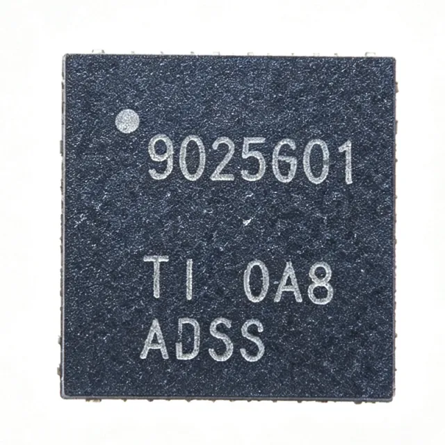
BQ25601RTWR - 3A I2C Buck Battery Charger | Texas Instruments
料号: BQ25601RTWR ✓ 量产中| 数量 | 单价 | 小计 |
|---|---|---|
| 1 | $1.02 | $1.02 |
| 10 | $0.92 | $9.20 |
| 100 | $0.75 | $75.00 |
| 500 | $0.58 | $290.00 |
| 1,000 | $0.46 | $460.00 |
BQ25601RTWR 概述
A battery charger IC is a power management integrated circuit that regulates the charging of rechargeable batteries, ensuring safe and efficient charging while protecting the battery from overvoltage, overcurrent, and overtemperature conditions. Within the power management IC hierarchy, the BQ25601 integrates a synchronous buck converter, NVDC power path management, and an I2C interface, enabling dynamic power management between the input source, system load, and battery. This allows the system to boot and operate even when the battery is deeply discharged or absent.
Key features include a 3A fast-charge current, adjustable charge voltage from 3.856V to 4.624V, high input voltage support up to 13.5V, and an integrated bootstrap diode for the high-side gate drive that simplifies system design and reduces BOM count. The I2C serial interface provides programmable charge current, charge voltage, and input current limits, and supports On-The-Go (OTG) boost operation from the battery to power attached USB peripherals.
The BQ25601 uses a synchronous buck topology with a high-efficiency power stage, achieving approximately 92% efficiency at typical operating conditions. Input voltage and current regulation (DPM) deliver maximum charging power from USB adapters and other sources, while protections include input overvoltage, battery overvoltage, and thermal shutdown.
Typical applications include smartphones, tablets, portable speakers, power banks, and industrial or medical handheld devices requiring reliable high-current single-cell charging with power path management.
When designing with the BQ25601, ensure a proper PCB layout with thermal vias under the exposed pad and adequate copper area for heat dissipation at 3A charge currents, and configure I2C registers to set the desired charge parameters. According to TI datasheet (bq25601.pdf), pricing at authorized distributors starts around $0.37 at LCSC as of 2026-08-30.
直接替换替代料: BQ25601RTWR ——相同封装,引脚兼容。需要 PCB 改动的不同封装料号已排除。
快速对比工具——选择替代料号进行并排对比:
BQ25601RTWT
✅ 直接替换📋 参考替代料(不在目录中)
BQ25892RTWT
✅ 直接替换📋 参考替代料(不在目录中)
BQ25895RTWT
✅ 直接替换 ⚠️ 规格未核验📋 参考替代料(不在目录中)
BQ25601QRTWRQ1
✅ 直接替换 ⚠️ 规格未核验✓ 有现货
$1.85 / 个
查看数据手册 →BQ25896RTWT
✅ 直接替换 ⚠️ 规格未核验📋 参考替代料(不在目录中)
BQ25601RTWR 规格参数
| 功能 | Single-cell Li-Ion/Li-Polymer buck battery charger with NVDC power path |
| Chemistry | Li-Ion / Li-Polymer |
| Maximum Charge Current | 3 A |
| 输入电压范围 | 3.9 V to 13.5 V |
| Absolute Maximum Input Voltage | 14 V |
| Charge Voltage Range | 3.856 V to 4.624 V |
| Series Cells | 1 |
| Control Interface | I2C |
| Power Path Management | NVDC (Narrow VDC) |
| OTG Boost Mode | Yes |
| Integrated Bootstrap Diode | Yes |
| 工作温度 | -40C to +85C |
| 封装 | 24-WQFN (4x4 mm) RTW with exposed pad |
| 安装类型 | Surface Mount |
| RoHS 状态 | Compliant |
BQ25601RTWR 引脚配置
| 引脚 1 | BTST — Bootstrap for high-side gate driver (internal diode from REGN) |
| 引脚 2 | REGN — LDO output for gate drive, 5V typical |
| 引脚 3 | OTG — OTG mode enable input |
| 引脚 4 | ACOK — Input source indication open-drain output |
| 引脚 5 | I2C SCL — I2C clock input |
| 引脚 6 | SDA — I2C data input/output |
| 引脚 7 | INT — Interrupt open-drain output |
| 引脚 8 | STAT — Charge status indication output |
| 引脚 9 | PGND — Power ground |
| 引脚 10 | SW — Switching node of buck converter |
| 引脚 11 | BAT — Battery connection / sense |
| 引脚 12 | SYS — NVDC system output |
| 引脚 13 | CS — [DATA_NEEDED: exact pin name] |
| 引脚 14 | ACN — [DATA_NEEDED: exact pin name] |
| 引脚 15 | ACP — [DATA_NEEDED: exact pin name] |
| 引脚 16 | VAC — Input voltage sense / supply |
| 引脚 17 | DSEL — [DATA_NEEDED: exact pin name] |
| 引脚 18 | ILIM — [DATA_NEEDED: exact pin name] |
| 引脚 19 | TS — Battery temperature sensing via NTC |
| 引脚 20 | AGND — Analog ground |
典型应用
BQ25601RTWR 适用于 6 应用s: Smartphone Fast Charging, Tablets and e-Readers, Power Banks with OTG Output, Portable Bluetooth Speakers, Industrial Handheld Devices, Medical Portable Diagnostics.
Smartphone Fast Charging
The BQ25601RTWR is ideal for smartphone charging because its 3A fast-charge current and 3.9V-13.5V input range support both 5V standard and 9V-class adapters. The NVDC power path lets the phone boot instantly even with a fully depleted battery, while input current DPM prevents adapter overload. With approximately 92% buck efficiency and an integrated bootstrap diode, it reduces BOM count and thermal load in dense handset layouts.
推荐
Tablets and e-Readers
Tablets benefit from the BQ25601's 3A charge capability, which refills large single-cell packs quickly, and its 4.624V maximum charge voltage covering high-capacity Li-Polymer cells. NVDC power path management guarantees stable system voltage during simultaneous charging and operation. The I2C interface lets the application processor dynamically adjust charge current based on thermal conditions, and OTG mode powers accessories from the battery at 5V-class output.
推荐
Power Banks with OTG Output
In power banks, the BQ25601RTWR handles both charging from USB adapters and OTG boost discharge to 5V output from the battery, all in one IC. The 13.5V input limit accepts multi-voltage adapter inputs, while 3A charging shortens recharge time of the internal pack. The I2C register set enables LED-indicated state-of-charge management and automatic switchover between adapter and battery power without external switchover circuitry.
推荐
Portable Bluetooth Speakers
Battery-powered speakers use the BQ25601RTWR's NVDC power path so audio amplifiers receive a regulated system rail regardless of battery sag during high-current playback. The 3A charge current minimizes recharge downtime, and OTG mode can power USB accessories. Thermal shutdown and battery overvoltage protection protect the pack during charging inside acoustically sealed enclosures with limited airflow, a common constraint in speaker industrial design.
推荐
Industrial Handheld Devices
Industrial scanners, meters, and data loggers charge from varied adapters, and the BQ25601's wide 3.9V-13.5V input plus input overvoltage protection tolerates noisy or miswired supplies. The -40C to +85C operating range suits harsh environments, and I2C telemetry (charge status, fault registers) lets the host MCU report battery health. NVDC power path ensures uptime during battery swap, which is critical for continuous data collection in the field.
推荐
Medical Portable Diagnostics
Portable medical instruments require predictable charging and uninterrupted operation; the BQ25601RTWR provides both. Its programmable 3.856V-4.624V charge voltage supports medical-grade cell requirements, and NVDC power path maintains a clean regulated system rail for sensitive analog front-ends during charging. The I2C interface allows firmware-controlled charge termination criteria, and built-in overvoltage and thermal protections support the safety requirements of handheld diagnostic and monitoring devices.
推荐
推荐产品汇总
工程参考数据: BQ25601RTWR ——对比、设计指导和合规信息。
选型指南
与替代料对比
| 参数 | 本产品 | BQ25601RTWT | BQ25892RTWT | BQ25895RTWT | BQ25601QRTWRQ1 |
|---|---|---|---|---|---|
| Package | 24-WQFN (4x4 mm) | 24-WQFN (4x4 mm) - same | 24-WQFN (4x4 mm) - same | 24-WQFN (4x4 mm) - same | 24-WQFN (4x4 mm) - same |
| Brand | Texas Instruments | Texas Instruments | Texas Instruments | Texas Instruments | Texas Instruments |
| Max Charge Current | 3 A | 3 A | 3 A (higher OTG discharge) | 5 A | 3 A |
| Max Input Voltage | 13.5 V | 13.5 V | 14 V | 14 V | 13.5 V |
| Charge Voltage Range | 3.856 V to 4.624 V | 3.856 V to 4.624 V | 3.84 V to 4.624 V | 3.84 V to 4.624 V | 3.856 V to 4.624 V |
| Interface | I2C | I2C (identical register map) | I2C (different registers) | I2C (different registers) | I2C (similar registers) |
| NVDC Power Path + OTG | Yes / Yes | Yes / Yes | Yes / Yes | Yes / Yes | Yes / Yes |
| Automotive AEC-Q100 | No | No | No | No | Yes |
关键差异点
- Integrated bootstrap diode (对比 BQ25892RTWT)
- True drop-in twin availability (对比 BQ25601RTWT)
- Lower cost than higher-current family parts (对比 BQ25895RTWT)
设计说明
At 3A charge current with a large input-to-battery delta (e.g., 12V input to 4V battery), conduction and switching losses concentrate in the 4x4mm QFN exposed pad. Provide a solid ground plane with at least a 5x5 array of thermal vias (0.3mm drill) under the pad to keep junction temperature within limits at 85C ambient. TI's BQ25601 EVM layout is a proven starting reference.
Keep the SW node, BTST, and input loop as compact as possible: place the input capacitor within 2mm of ACP/ACN and VAC, and the inductor close to SW. Separate AGND and PGND planes, joining at a single star point under the IC. Route I2C (SCL/SDA) away from the SW node to avoid register corruption from switching noise.
Always connect the TS pin to a 10k NTC (or fixed divider) - floating TS can block charging due to temperature fault. When migrating to BQ25892, remember the I2C register maps differ even though the pinout is identical (per TI E2E forum); update firmware before powering up. Observe the 14V absolute maximum input; add input TVS for adapters without OVP.
合规信息
RoHS compliant per DigiKey product listing (Charger IC Lithium Ion/Polymer, 24-WQFN). Not AEC-Q100 qualified - choose BQ25601QRTWRQ1 for automotive. REACH and halogen-free status per TI quality pages.







