STM32L051C8T6 - Ultra-Low-Power ARM Cortex-M0+ MCU | STMicroelectronics
料号: STM32L051C8T6 ✓ 量产中| 数量 | 单价 | 小计 |
|---|---|---|
| 1 | $1.6909 | $1.69 |
| 10 | $1.2212 | $12.21 |
| 100 | $1.0803 | $108.03 |
| 500 | $1.0333 | $516.65 |
| 1,000 | $0.9864 | $986.40 |
| 1,500 | $0.9773 | $1,465.95 |
STM32L051C8T6 概述
What is an ultra-low-power microcontroller? An ultra-low-power microcontroller is a type of embedded processor designed to minimize energy consumption while maintaining computational capability. It fits within the broader hierarchy: ARM Cortex-M0+ core -> 32-bit microcontroller -> embedded processor -> semiconductor. These devices are optimized for applications where battery life is critical, such as IoT sensors, wearables, and portable medical devices. The STM32L0 series specifically targets the low-power segment with multiple sleep modes and dynamic voltage scaling.
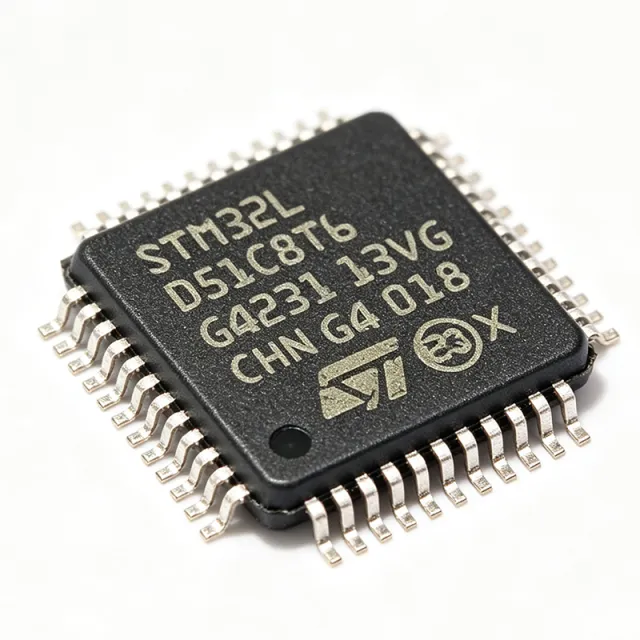
Key features include a 12-bit ADC with hardware oversampling, a low-power UART, and a real-time clock (RTC) with calendar. The device supports a wide operating temperature range of -40°C to +85°C and is available in a 48-pin LQFP package. The STM32L051C8T6 also includes a unique device ID, CRC calculation unit, and a true random number generator (RNG) for security applications.
Technically, the STM32L051C8T6 is built on ST's ultra-low-power technology, featuring a flexible clock tree with multiple internal/external oscillators. It supports a 1.8V to 3.6V power supply and has a typical current consumption of 3.4 µA in Stop mode with RTC, and 0.29 µA in Standby mode. The device also includes a brown-out reset (BOR) and power-on reset (POR) for reliable operation.
Typical applications include IoT sensor nodes, smart home devices, portable medical monitors, and industrial sensor interfaces. Its low power consumption and rich analog peripherals make it suitable for battery-powered designs where long operational life is required.
When designing with this MCU, pay attention to the power supply decoupling and the selection of the appropriate low-power mode for your application. Use the STM32CubeMX tool to configure the clock tree and peripherals efficiently.
This page synthesizes distributor pricing, drop-in alternatives, and practical design notes not found in the ST datasheet, providing a comprehensive resource for engineers evaluating the STM32L051C8T6.
直接替换替代料: STM32L051C8T6 ——相同封装,引脚兼容。需要 PCB 改动的不同封装料号已排除。
本系列中的变体
可与以下型号直接替换的同系列型号: STM32L051C8T6 (相同外形与封装尺寸) ——差异在于 Communication Interfaces, Core, Operating Temperature, Package, Timers.
快速对比工具——选择替代料号进行并排对比:
STM32L051C8T6TR
📋 参考替代料(不在目录中)
STM32L051C8T7
📋 参考替代料(不在目录中)
STM32L051C8T6D
📋 参考替代料(不在目录中)
STM32L051C8T6 最大额定值与电气特性
| Core | ARM Cortex-M0+ |
| Max Clock Frequency | 32 MHz |
| Flash Memory | 64 KB |
| SRAM | 8 KB |
| 电源电压 | 1.8 V to 3.6 V |
| 工作温度 | -40°C to +85°C |
| 封装 | LQFP-48 (7x7 mm) |
| ADC Resolution | 12-bit |
| ADC Channels | 10 |
| Communication Interfaces | I2C, SPI, USART |
| Timers | 5x 16-bit, 1x 32-bit |
| RTC | Yes (with calendar) |
| Low-Power Modes | Sleep, Low-power run, Low-power sleep, Stop, Standby |
| Standby Current | 0.29 µA |
| Stop Mode Current (with RTC) | 3.4 µA |
| RoHS 状态 | Compliant |
STM32L051C8T6 引脚配置
| 引脚 1 | VBAT — Battery backup supply for RTC |
| 引脚 2 | PC14 — GPIO / OSC32_IN |
| 引脚 3 | PC15 — GPIO / OSC32_OUT |
| 引脚 4 | OSC_IN — External clock input |
| 引脚 5 | OSC_OUT — External clock output |
| 引脚 6 | NRST — Reset (active low) |
| 引脚 7 | VSSA — Analog ground |
| 引脚 8 | VDDA — Analog power supply |
| 引脚 9 | PA0 — GPIO / ADC_IN0 |
| 引脚 10 | PA1 — GPIO / ADC_IN1 |
| 引脚 11 | PA2 — GPIO / USART2_TX |
| 引脚 12 | PA3 — GPIO / USART2_RX |
| 引脚 13 | PA4 — GPIO / SPI1_NSS |
| 引脚 14 | PA5 — GPIO / SPI1_SCK |
| 引脚 15 | PA6 — GPIO / SPI1_MISO |
| 引脚 16 | PA7 — GPIO / SPI1_MOSI |
| 引脚 17 | PB0 — GPIO / ADC_IN8 |
| 引脚 18 | PB1 — GPIO / ADC_IN9 |
| 引脚 19 | PB2 — GPIO / BOOT1 |
| 引脚 20 | PB10 — GPIO / I2C2_SCL |
| 引脚 21 | PB11 — GPIO / I2C2_SDA |
| 引脚 22 | VSS — Ground |
| 引脚 23 | VDD — Power supply |
| 引脚 24 | PB12 — GPIO / SPI2_NSS |
| 引脚 25 | PB13 — GPIO / SPI2_SCK |
| 引脚 26 | PB14 — GPIO / SPI2_MISO |
| 引脚 27 | PB15 — GPIO / SPI2_MOSI |
| 引脚 28 | PA8 — GPIO / MCO |
| 引脚 29 | PA9 — GPIO / USART1_TX |
| 引脚 30 | PA10 — GPIO / USART1_RX |
| 引脚 31 | PA11 — GPIO / USART1_CTS |
| 引脚 32 | PA12 — GPIO / USART1_RTS |
| 引脚 33 | PA13 — GPIO / SWDIO |
| 引脚 34 | PA14 — GPIO / SWCLK |
| 引脚 35 | PA15 — GPIO / SPI1_NSS |
| 引脚 36 | PB3 — GPIO / SPI1_SCK |
| 引脚 37 | PB4 — GPIO / SPI1_MISO |
| 引脚 38 | PB5 — GPIO / SPI1_MOSI |
| 引脚 39 | PB6 — GPIO / I2C1_SCL |
| 引脚 40 | PB7 — GPIO / I2C1_SDA |
| 引脚 41 | BOOT0 — Boot mode selection |
| 引脚 42 | PB8 — GPIO / I2C1_SCL |
| 引脚 43 | PB9 — GPIO / I2C1_SDA |
| 引脚 44 | VSS — Ground |
| 引脚 45 | VDD — Power supply |
| 引脚 46 | PC13 — GPIO / RTC_TAMP1 |
| 引脚 47 | PC14 — GPIO / OSC32_IN |
| 引脚 48 | PC15 — GPIO / OSC32_OUT |
典型应用
STM32L051C8T6 适用于 6 应用s: IoT Sensor Nodes, Smart Home Devices, Portable Medical Monitors, Industrial Sensor Interfaces, Wearable Devices, Energy Harvesting Systems.
IoT Sensor Nodes
The STM32L051C8T6 is ideal for IoT sensor nodes due to its ultra-low-power modes and multiple communication interfaces. Its 0.29 µA standby current allows battery-powered sensors to operate for years. The 12-bit ADC can interface with various analog sensors, while I2C/SPI/USART enable connection to wireless modules like LoRa or BLE. In a typical node, the MCU wakes periodically, reads sensors, and transmits data, minimizing energy consumption. The wide supply voltage range (1.8V-3.6V) allows direct battery connection without a regulator, simplifying the design and improving efficiency.
推荐
Smart Home Devices
The STM32L051C8T6 is well-suited for smart home devices such as smart thermostats, lighting controls, and security sensors. Its low power consumption enables battery-powered operation, while the RTC with calendar allows scheduling and time-stamping. The device can interface with various sensors and actuators through its GPIO and communication interfaces. For example, in a smart thermostat, the MCU reads temperature sensors, controls a relay or motor, and communicates with a central hub via UART or I2C. The low-power modes ensure minimal energy usage when idle, extending battery life in wireless devices.
推荐
Portable Medical Monitors
The STM32L051C8T6 is suitable for portable medical monitors like heart rate monitors, glucose meters, and pulse oximeters. Its low power consumption is critical for battery-operated devices that need to last long between charges. The 12-bit ADC can accurately sample analog signals from sensors, and the low-power modes allow the device to sleep between measurements. The MCU's small footprint (LQFP-48) enables compact device designs. In a pulse oximeter, the MCU processes signals from an optical sensor, calculates oxygen saturation, and displays results on an LCD, all while maintaining low energy consumption.
推荐
Industrial Sensor Interfaces
The STM32L051C8T6 is used in industrial sensor interfaces for monitoring temperature, pressure, and flow. Its robust operating temperature range (-40°C to +85°C) and wide supply voltage make it suitable for harsh environments. The device can interface with 4-20 mA loops, RTDs, and thermocouples through its ADC and comparators. In a typical industrial sensor node, the MCU reads sensor data, performs calibration, and communicates via RS-485 or CAN (through external transceiver). The low-power modes are less critical here, but the MCU's reliability and peripheral set make it a cost-effective choice.
推荐
Wearable Devices
The STM32L051C8T6 is ideal for wearable devices like fitness trackers and smartwatches due to its ultra-low power consumption and small package. The MCU can run on a small coin cell battery for months, thanks to its low standby current and efficient sleep modes. It can interface with accelerometers, heart rate sensors, and displays. In a fitness tracker, the MCU collects motion data from an accelerometer, processes steps, and communicates with a smartphone via BLE (through an external module). The 1.8V-3.6V supply range allows direct battery connection, and the RTC can track time and date.
推荐
Energy Harvesting Systems
The STM32L051C8T6 is well-suited for energy harvesting systems that collect energy from solar, thermal, or vibration sources. Its ultra-low power consumption allows it to operate with the limited energy harvested. The MCU can wake up periodically to take measurements and transmit data, then return to a low-power state. The wide supply voltage range (1.8V-3.6V) is compatible with energy harvesting power management ICs. In a solar-powered sensor node, the MCU manages the power budget, reads sensors, and sends data via a low-power radio, ensuring sustainable operation without batteries.
推荐
推荐产品汇总
工程参考数据: STM32L051C8T6 ——对比、设计指导和合规信息。
选型指南
与替代料对比
| 参数 | 本产品 | STM32L051C8T6TR | STM32L051C8T7 | STM32L051C8T6D |
|---|---|---|---|---|
| Package | LQFP-48 | LQFP-48 - same | LQFP-48 - same | LQFP-48 - same |
| Flash Memory | 64 KB | 64 KB | 64 KB | 64 KB |
| SRAM | 8 KB | 8 KB | 8 KB | 8 KB |
| Max Clock Frequency | 32 MHz | 32 MHz | 32 MHz | 32 MHz |
| Operating Temperature Range | -40°C to +85°C | -40°C to +85°C | -40°C to +105°C | -40°C to +85°C |
| Standby Current | 0.29 µA | 0.29 µA | 0.29 µA | 0.29 µA |
| ADC Resolution | 12-bit | 12-bit | 12-bit | 12-bit |
| Communication Interfaces | I2C, SPI, USART | I2C, SPI, USART | I2C, SPI, USART | I2C, SPI, USART |
| Price (1000 pcs) | $1.82 | $1.82 | $2.10 | $1.90 |
关键差异点
- Ultra-low standby current of 0.29 µA (对比 STM32L071C8T6)
- Cost-effective 64 KB Flash option (对比 STM32L071C8T6)
- Pin-compatible with higher-end STM32L0 variants (对比 STM32L071C8T6)
设计说明
Decouple the VDD and VDDA pins with 100 nF ceramic capacitors placed as close as possible to the pins. Additionally, use a 4.7 µF capacitor on VDDA for analog noise filtering. For battery-powered designs, consider using the VBAT pin for RTC backup with a separate coin cell to maintain timekeeping when the main supply is removed.
Ensure a solid ground plane under the LQFP-48 package to minimize noise and improve thermal performance. Route the crystal oscillator (OSC_IN/OSC_OUT) with short traces and keep them away from high-speed digital signals. Use ground vias around the crystal to reduce EMI.
Do not leave unused GPIO pins floating; configure them as outputs or enable internal pull-ups/pull-downs to avoid excessive leakage current. Also, ensure the BOOT0 pin is properly tied to ground for normal boot from Flash. When using low-power modes, verify that all peripherals are properly disabled to achieve the specified standby current.
合规信息
RoHS compliant per STMicroelectronics product page. Not AEC-Q100 qualified - this is a general-purpose MCU, not automotive grade.