DC-DC Converters
Products (770)

UC2825DWTR - 1A, 30V High-Speed PWM Controller | Texas Instruments
The Texas Instruments UC2825DWTR is a high-speed, double-ended PWM controller delivering up to 1A peak output drive current in a 16-pin SOIC (DW) package. It supports switching frequencies up to 1 MHz and is designed for topologies including Boost, Flyback, Forward, Full-Bridge, Half-Bridge, and Push-Pull converters, with a wide 10V to 30V supply range and enhanced 9.2V/8.4V UVLO thresholds. A PWM controller (Pulse-Width Modulation controller) is a semiconductor device that regulates power converter switching by modulating the duty cycle of the driver output stage. PWM controllers belong to the hierarchy: PWM controller -> switching controller -> DC-DC controller -> power management IC -> semiconductor. Compared with simple voltage regulators, PWM controllers provide the high-side/low-side gate drive, current sensing, and protection logic needed to build discrete switching converters. Key features of the UC2825DWTR include a 1V-threshold current-limit comparator, a TTL-compatible shutdown pin, a soft-start pin that doubles as a maximum duty-cycle clamp (programmable to 80%), and an under-voltage lockout with 800 mV of hysteresis. The output stage delivers ±1.5 A peak totem-pole drive, fully latched logic prevents multiple output pulses, and an internal 5.1V reference powers the control loop. Architecturally, the UC2825 uses a bipolar process with a double-ended push-pull output stage. The high peak drive current and 30V rating allow direct gate drive of power MOSFETs or small IGBTs in high-frequency SMPS designs. The fully-latched comparator logic eliminates jitter and double-pulsing that can occur in edge-triggered designs, producing clean gate waveforms at high frequency. Typical applications include telecom and server DC-DC converters, isolated bus converters using push-pull or bridge topologies, industrial power supplies, motor drivers, and high-frequency SMPS modules. The wide input range and high peak drive current make it well suited to 48V telecom rails, industrial 24V systems, and automotive-grade variants exist as UC2825-Q1. When designing with this device, choose external R/C timing values for the oscillator to set frequency and maximum duty cycle. Use Kelvin connections to the current-sense resistor for accurate 1V-threshold current limiting, and place bypass capacitors close to VCC and the 5.1V reference pin to maintain stability. This page synthesizes distributor pricing, drop-in compatible alternatives, and practical design notes not found in the manufacturer datasheet alone.

UC3824 - 1.5A High Speed PWM Controller | Texas Instruments
The Texas Instruments UC3824 is a high-speed, double-ended PWM controller designed for switch-mode power supplies requiring operating frequencies up to 1 MHz. It integrates a 30-V, 1.5-A totem-pole output stage capable of driving power MOSFETs directly, along with a 9.2-V/8.4-V undervoltage lockout (UVLO) and a maximum duty cycle of 85%. The device is available in a 16-pin PDIP package (UC3824N) and operates over the commercial temperature range of 0°C to 70°C. A PWM controller is an integrated circuit that generates the pulse-width-modulated signals used to control the switching elements in a DC-DC converter or power supply. It forms the core of the control loop, regulating output voltage or current by varying the duty cycle of the switching waveform. The UC3824 belongs to the family of current-mode PWM controllers, which offer superior line regulation and simpler compensation compared to voltage-mode controllers. In the hierarchy of power management, it sits between the power stage (MOSFETs, transformers) and the supervisory circuitry, providing the precise timing and drive signals essential for efficient power conversion. Key features of the UC3824 include a 50-ns propagation delay to output, enabling high-frequency operation with minimal phase lag. The dual totem-pole outputs can source and sink 1.5 A, providing robust gate drive for large MOSFETs. The device also includes a current-limit comparator with a 1-V threshold, a TTL-compatible shutdown port, and a soft-start pin that doubles as a maximum duty cycle clamp. The logic is fully latched to ensure jitter-free operation and prevent multiple pulses at the output. Technically, the UC3824 uses a fixed-frequency, current-mode architecture with an internal oscillator whose frequency is set by external timing components RT and CT. The ramp generator is designed so that the voltage at Pin 9 crosses the 1-V threshold at the same time the desired maximum volt-second product is reached, allowing precise control of the duty cycle. The device's high-speed comparator and latch ensure accurate cycle-by-cycle current limiting, making it suitable for demanding applications such as push-pull and half-bridge converters. Typical applications include switch-mode power supplies for telecommunications, industrial power converters, and battery chargers. The UC3824's high-frequency capability allows for smaller magnetic components, reducing overall system size and cost. Its double-ended output configuration makes it ideal for push-pull and full-bridge topologies where two interleaved drive signals are required. When designing with the UC3824, careful attention must be paid to grounding and bypassing, as the high-speed switching can introduce noise. A ground plane is highly recommended, and the timing components should be placed close to the IC to minimize parasitic inductance. The soft-start pin should be used to limit inrush current during startup, and the current-limit threshold should be set appropriately for the application.
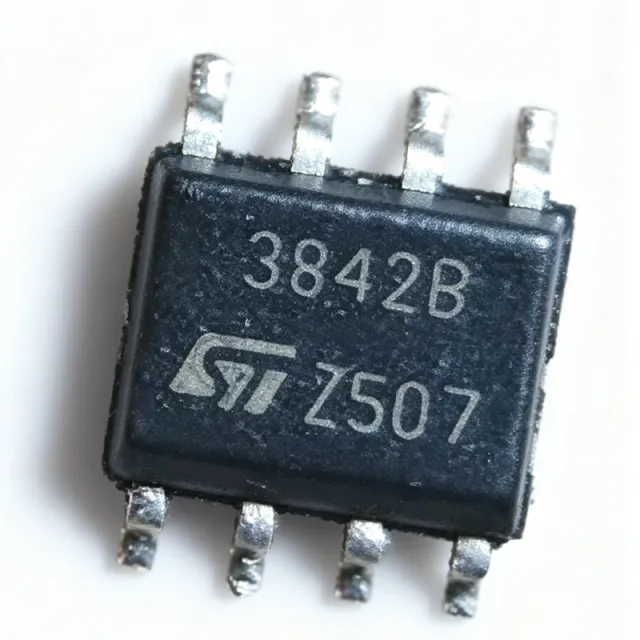
UC3842BD1 - Current Mode PWM Controller | STMicroelectronics | SMPS
The STMicroelectronics UC3842BD1 is a high-performance current-mode PWM controller designed for off-line and DC-to-DC converter applications. It operates with an input voltage range of 7.5V to 30V and provides a 1A peak output current for driving power MOSFETs. The device is available in an SOIC-8 package, making it suitable for compact power supply designs. A current-mode PWM controller is a type of switching regulator control IC that regulates output voltage by comparing the output error signal with a current-sense signal from the power switch. This architecture provides inherent feed-forward compensation, cycle-by-cycle current limiting, and simplified loop compensation compared to voltage-mode controllers. The UC3842BD1 belongs to the UC3842 family of PWM controllers, which are widely used in AC-DC adapters, battery chargers, and industrial power supplies. Key features of the UC3842BD1 include a trimmed oscillator for precise frequency control, an under-voltage lockout (UVLO) with hysteresis, a 5V reference output, and a high-gain error amplifier. The oscillator frequency is programmable up to 500 kHz, allowing designers to optimize transformer size and efficiency. The device also features a low startup current of 0.5 mA, which is critical for efficient power-up in battery-powered systems. The UC3842BD1 uses a fixed-frequency current-mode architecture with a maximum duty cycle of 96%. The error amplifier has a bandwidth of 1 MHz, enabling fast transient response. The current-sense comparator has a threshold of 1V, providing accurate cycle-by-cycle current limiting. The device is designed to operate over a junction temperature range of -40°C to +150°C, ensuring reliability in harsh environments. Typical applications include switch-mode power supplies (SMPS) for consumer electronics, industrial power converters, and battery chargers. The UC3842BD1 is also used in flyback and boost converter topologies, where its current-mode control simplifies loop compensation and improves line regulation. When designing with the UC3842BD1, ensure that the current-sense resistor is placed close to the IC to minimize parasitic inductance. The oscillator timing resistor and capacitor should be located near the RT/CT pin to reduce noise coupling. Proper grounding and decoupling of the VCC pin are essential for stable operation. This page synthesizes distributor pricing, drop-in alternatives, and practical design notes not found in the STMicroelectronics datasheet, providing engineers with a comprehensive resource for selecting and implementing the UC3842BD1.

UC3842BD1013TR - Current Mode PWM Controller | STMicroelectronics
The UC3842BD1013TR is a high-performance current-mode PWM controller from STMicroelectronics, designed for off-line and DC-to-DC converter applications. It operates as a boost or flyback regulator with isolation capability, providing a cost-effective solution for power supply designs. The device is housed in an 8-SOIC package and supports a switching frequency up to 500 kHz, with a peak output current of 1 A. Its input voltage is rated at 15 V, and it operates over a temperature range of 0°C to 70°C. A current-mode PWM controller is a type of switching regulator controller that uses the inductor current as a feedback signal to modulate the duty cycle of the output switch. This architecture provides inherent cycle-by-cycle current limiting, improved transient response, and simplified loop compensation compared to voltage-mode controllers. The UC3842BD1013TR belongs to the UC3842 family, which is widely used in AC-DC adapters, battery chargers, and isolated DC-DC converters. Key features of the UC3842BD1013TR include a trimmed oscillator for precise frequency control, current-mode operation up to 500 kHz, automatic feed-forward compensation, latching PWM for cycle-by-cycle current limiting, and an internally trimmed reference. These features enable stable and reliable operation in demanding power conversion applications. The device also includes under-voltage lockout (UVLO) and a totem-pole output stage capable of sourcing and sinking 1 A peak current to drive power MOSFET gates directly. Technically, the UC3842BD1013TR integrates a 5V reference, an error amplifier, a current-sense comparator, and a PWM latch. The oscillator frequency is set by an external resistor and capacitor, allowing designers to program the switching frequency from 50 kHz to 500 kHz. The current-sense input provides overcurrent protection by comparing the sensed voltage to a 1V threshold. The device's low startup current and low operating current contribute to high efficiency in power supplies. Typical applications include switch-mode power supplies (SMPS) for consumer electronics, industrial power converters, and isolated flyback converters for telecom and networking equipment. The UC3842BD1013TR is particularly suited for designs requiring a simple, reliable current-mode controller with minimal external components. When designing with this controller, ensure proper PCB layout to minimize noise on the current-sense and feedback paths. Use a low-ESR capacitor on the VCC pin and place the timing components close to the IC. Adequate thermal relief on the SOIC package is recommended for high-power applications.

UCC25800-Q1 - Ultra-Low EMI Transformer Driver | Texas Instruments
The Texas Instruments UCC25800-Q1 is an ultra-low EMI transformer driver designed for isolated bias supplies in automotive and industrial applications. It integrates the switching power stage, control, and protection circuits into an 8-pin HVSSOP (DGN) package with an exposed thermal pad. The device operates from a wide input voltage range of 9 V to 34 V and delivers up to 9 W from a 34-V input. It uses an LLC resonant topology, which allows the use of transformers with higher leakage inductance but much smaller parasitic primary-to-secondary capacitance, significantly reducing common-mode EMI. A transformer driver is a power management IC that generates an AC voltage from a DC input to drive an isolation transformer, providing isolated DC outputs for gate drivers, sensors, and other bias supplies. It sits within the power management hierarchy: transformer driver -> isolated bias supply -> power management IC -> semiconductor. The UCC25800-Q1 simplifies isolated bias supply design by integrating the half-bridge power stage, oscillator, and protection features, eliminating the need for external high-side drivers and complex control loops. Key features include programmable switching frequency from 0.1 MHz to 1.2 MHz, enabling optimization for transformer size and EMI. The device offers a dedicated multi-function pin for external disabling and fault code reporting, enhancing system reliability. Its ultra-low EMI performance is achieved through the LLC topology and low interwinding capacitance transformer design, making it ideal for noise-sensitive automotive environments such as electric vehicles (EVs) and hybrid electric vehicles (HEVs). The UCC25800-Q1 integrates a high-efficiency half-bridge driver with adaptive dead-time control, reducing switching losses and improving efficiency. The device includes comprehensive protection features such as overcurrent protection, thermal shutdown, and undervoltage lockout (UVLO). The 8-pin DGN package with thermal pad provides excellent thermal handling, allowing operation at high ambient temperatures up to 125°C. Typical applications include isolated gate driver bias supplies for traction inverters, on-board chargers, DC-DC converters, and battery management systems in automotive. It is also suitable for industrial isolated power supplies, motor drives, and renewable energy systems. The wide input range and programmable frequency make it versatile for various power levels and isolation requirements. When designing with the UCC25800-Q1, ensure proper transformer selection with low interwinding capacitance to maximize EMI benefits. The SYNC pin allows external synchronization, but the external frequency must be set such that half the sync frequency is between 15% and 30% of the nominal frequency to maintain output regulation. Adequate input decoupling and a low-ESR output capacitor are essential for stable operation.

UCC28019ADR - 65kHz CCM PFC Controller | Texas Instruments
The Texas Instruments UCC28019ADR is an 8-pin active Power Factor Correction (PFC) controller using boost topology in Continuous Conduction Mode (CCM). Designed for systems from 100 W to over 2 kW with wide-range universal AC line input, it operates at a fixed 65-kHz frequency with a maximum duty cycle of 98% (typ). Start-up current during undervoltage lockout is below 200 uA, and low-power standby mode is entered by pulling the VSENSE pin below 0.77 V. The DR suffix denotes the 8-pin SOIC (D) package supplied in tape and reel. A PFC controller is a specialized power management IC that shapes the input current of an AC-DC power supply to be sinusoidal and in phase with input voltage, improving power factor and reducing harmonics to meet standards such as IEC 61000-3-2. In a boost PFC, the controller regulates the DC bus voltage while forcing input current to follow input voltage. PFC controllers belong to the broader family of switch-mode power supply control ICs within power management. Key features include the 8-pin solution that reduces external component count, wide-range universal AC input, fixed 65-kHz switching, output over/under voltage protection, open-loop protection, overcurrent protection, and enhanced start-up and transient response. Average current mode control delivers stability and noise immunity, supported by an internal reference, error amplifier, and PWM comparator. UVLO thresholds are 10.5 V on and 9.5 V off, with a maximum Vin of 21 V. Typical applications include desktop computer and server power supplies, telecom rectifiers, industrial power systems, LED lighting drivers, and battery chargers that must meet power quality regulations. The controller supports both sub-150 W and above-750 W application ranges. When designing with the UCC28019ADR, keep gate drive and current-sense paths short and low inductance, place the sense resistor near the IC with a Kelvin connection, and avoid accidental triggering of the 0.77 V VSENSE standby threshold during normal operation.

UCC28019AQDRQ1 - 65kHz CCM PFC Controller, AEC-Q100 | TI
The Texas Instruments UCC28019AQDRQ1 is an AEC-Q100 qualified 8-pin active Power Factor Correction (PFC) controller that uses boost topology operating in Continuous Conduction Mode (CCM) at a fixed 65 kHz switching frequency. It is suitable for systems from 100 W to greater than 2 kW over a wide-range universal AC line input, packaged in an 8-SOIC (D) surface-mount package. A PFC controller is a power management IC that shapes the input current of an AC-DC converter so it follows the sinusoidal line voltage, raising power factor and reducing harmonic distortion to meet IEC harmonic-current requirements. PFC pre-regulators sit between the bridge rectifier and downstream DC-DC stage in the broader power-supply hierarchy. Key features include an 8-pin solution that senses neither line voltage nor line frequency, reducing external component count; a maximum duty cycle of 97%; and start-up current below 200 uA during undervoltage lockout, minimizing startup loss. Low-power standby mode is controlled by pulling the VSENSE pin below 0.77 V, enabling efficient no-load and light-load system behavior. Internal protection includes soft start, open-loop detection, and overvoltage protection per the datasheet. Architecturally, the controller implements average-current-mode CCM control with soft, controlled on-times that reduce ripple current stress on the boost inductor and MOSFET compared with transition-mode approaches, making it well matched to higher-power designs where EMI filtering and peak-current stress dominate design cost. Typical applications include automotive onboard chargers and front-end AC-DC power supplies, telecom rectifiers, industrial power supplies in the several-hundred-watt to multi-kilowatt range, and server/storage front ends requiring high power factor over universal AC input. Design consideration: because the part operates in CCM, ensure the boost inductor is sized so inductor current remains continuous above minimum load, and add adequate slope compensation via the ICOMP network per the TI datasheet to avoid subharmonic oscillation.

UCC2808AQDR-1EP - 1A Push-Pull PWM Controller, 1MHz, 8-SOIC | TI
The Texas Instruments UCC2808AQDR-1EP is a BiCMOS, low-power, current-mode push-pull pulse-width modulator (PWM) housed in an 8-pin SOIC (D) package, qualified to Texas Instruments' "Enhanced Product" (EP) pedigree with extended temperature performance to 125°C and enhanced diminishing manufacturing sources (DMS) support. It integrates all control and drive circuitry required for off-line or DC-to-DC fixed-frequency current-mode switching power supplies, delivering dual 1A push-pull output stages that switch at half the oscillator frequency. A current-mode PWM controller is a type of switching power supply controller that regulates output voltage by directly controlling the peak inductor current each switching cycle, rather than only the duty cycle. The UCC2808AQDR-1EP belongs to the current-mode controller product family, sitting within the broader hierarchy of switching regulators -> DC-DC converters -> power management ICs -> semiconductors. Current-mode control provides inherent input-voltage feedforward, cycle-by-cycle current limiting, and simplified loop compensation compared to voltage-mode architectures, making it well-suited for both isolated and non-isolated topologies. Key features of this EP variant include a 1 MHz maximum switching frequency, 49% maximum duty cycle, 12.5V undervoltage lockout (UVLO) start-up threshold, dual 1A push-pull output drivers with active low assertion, and BiCMOS construction that reduces operating current versus bipolar predecessors. The EP designation additionally provides one assembly/test site, one fabrication site, qualification pedigree, and enhanced product-change notification for high-reliability applications. The internal oscillator is programmed via a single external resistor and capacitor pair, supporting flexible frequency design. Architecturally, the device combines a precision reference, error amplifier, current-sense comparator, and dual totem-pole output drivers on a single BiCMOS die. The push-pull output stage eliminates the need for an external gate-drive transformer in many half-bridge and full-bridge derived designs, while current-mode operation simplifies feedback loop design. The 8-pin SOIC footprint offers straightforward PCB integration in both retrofits and new converter layouts. Typical applications include industrial DC-DC converters, telecom isolated power modules, low-power offline auxiliary supplies, and battery-charging front-end stages. Designers often pair the controller with small MOSFETs or gate-driver transformers for 50W to 250W power levels, taking advantage of the high switching frequency to shrink magnetics and output filters. When designing with the UCC2808AQDR-1EP, place the timing RC components close to pins 6 and 7 to minimize noise pickup, and ensure the current-sense resistor connection to pin 2 is a short, kelvin-routed trace. The push-pull outputs require proper dead-time management by the external power stage to prevent shoot-through. This page consolidates distributor pricing, drop-in compatible variants across the same SOIC-8 footprint, and design notes specifically tailored to high-reliability push-pull converter implementations.
UCC28600D - 8-Pin Quasi-Resonant Flyback Green-Mode Controller | TI
The Texas Instruments UCC28600D is an 8-pin quasi-resonant flyback green-mode PWM controller designed for energy-efficient offline AC-DC converters, packaged in an 8-pin SOIC (D) and supporting switching frequencies from 40 kHz to 130 kHz. What is a quasi-resonant flyback controller? A quasi-resonant flyback controller is a type of AC-DC PWM (pulse-width modulation) controller that switches the MOSFET at the valley of the drain-voltage waveform instead of at a fixed frequency. This valley-switching technique minimizes switching losses, reduces EMI, and improves energy-efficiency at light loads, making it a key building block of modern green-mode switch-mode power supplies (SMPS). Key features include built-in advanced energy-saving features, frequency fold-back and green-mode operation that reduces switching losses and standby power consumption, integrated high level protection features, and a wide VDD operating range. The controller integrates high-level protection features and supports quasi-resonant operation to meet stringent world-wide energy efficiency requirements. Technically, the UCC28600 incorporates frequency fold-back and green-mode operation to reduce switching losses and improve light-load efficiency. Its quasi-resonant detection circuit senses the transformer's drain voltage and triggers turn-on at the first valley, reducing dv/dt and EMI. Internal protection features typically include over-current protection (OCP), over-temperature protection, under-voltage lockout (UVLO), and over-voltage protection (OVP), making it a complete controller for cost-effective, energy-efficient flyback converters. Typical applications include AC-DC adapters and chargers for portable equipment, auxiliary and standby power supplies for desktop PCs and TVs, white goods and appliance power, set-top boxes, and industrial low-power offline converters. Quasi-resonant operation makes it especially well suited to designs targeting ENERGY STAR, DoE Level VI, and EU CoC Tier 2 efficiency standards. When designing with this device, the transformer's primary-side leakage inductance and the auxiliary VDD winding must be sized correctly to ensure the controller stays above its UVLO threshold under all load transients. Failure to maintain adequate VDD margin is the most common cause of UCC28600 start-up or hiccup-mode issues in production designs. This page synthesizes distributor pricing, drop-in alternatives, and practical design notes not found in the manufacturer datasheet to support your component selection, BOM risk assessment, and second-sourcing decisions.
UCC28600TDRQ1 - 8-Pin Quasi-Resonant Flyback Green-Mode Controller | Texas Instruments
The Texas Instruments UCC28600TDRQ1 is an automotive-grade (AEC-Q100) 8-pin quasi-resonant flyback green-mode controller in an 8-SOIC package, switching at 40 kHz to 130 kHz across an 8 V to 32 V input range and dissipating 650 mW maximum. It targets isolated and non-isolated AC/DC adapters, LED drivers, and auxiliary supplies where world-wide energy efficiency standards must be met without compromising EMI performance. A quasi-resonant flyback controller is a current-mode PWM controller that switches the MOSFET at the drain-voltage valley rather than at a fixed frequency. This valley-switching technique (also called valley-skipping or QR operation) reduces switching losses, lowers EMI emissions, and improves light-load efficiency compared with conventional hard-switched flyback designs. Within the broader power-supply hierarchy, it sits between the bridge rectifier/PFC front end and the isolated transformer secondary, governing energy transfer during each switching cycle. Key features of the UCC28600TDRQ1 include quasi-resonant mode operation for reduced EMI and low switching losses, a green-mode controller with advanced energy-saving features, frequency foldback at light load, low standby current, and over-temperature/over-current protection. The -Q1 suffix denotes AEC-Q100 Grade 1 automotive qualification, supporting under-the-hood and infotainment applications that demand -40 °C to +105 °C operation. The internal high-voltage startup and frequency-jitter block minimize external component count, enabling a compact, low-BOM-count adapter. Internally, the device combines a current-mode control loop, a valley-detection comparator, a programmable minimum-frequency clamp, and a soft-start sequencer. The result is a controller that adapts its switching frequency to the instantaneous load: at heavy load the converter operates near 130 kHz at the drain valley; at light or no load it folds back to 40 kHz or lower to maintain efficiency. According to TI design calculator SLVC104, the loop compensation, transformer turns ratio, and primary inductance are jointly optimized around the UCC28600 to achieve >85 % average efficiency. Typical applications include smartphone and tablet AC/DC adapters (5 W to 65 W), notebook laptop chargers, standby/auxiliary supplies in LCD TVs and white goods, LED lighting drivers, and automotive 12 V battery-powered systems such as USB chargers and infotainment rails. Any flyback topology where world-wide energy standards (DoE Level VI, CoC Tier 2, ENERGY STAR) apply is a strong candidate. When designing with the UCC28600TDRQ1, the primary-side MOSFET's drain-voltage ringing must remain within the controller's valley-detection window; otherwise the converter will hard-switch and lose its EMI advantage. Use the SLVC104 design calculator to size the primary inductance and transformer turns ratio, and follow TI's reference layout to keep the drain-sense trace short and well-shielded. This page synthesizes distributor pricing, AEC-Q100 alternatives, drop-in package equivalents, and practical flyback design notes not found in the standalone manufacturer datasheet.
UCC28730-Q1 - PSR Flyback Controller, 5mW Standby | TI
The Texas Instruments UCC28730-Q1 is an automotive-qualified (AEC-Q100), zero-power standby primary-side regulation (PSR) flyback controller providing constant-voltage (CV) and constant-current (CC) output regulation without an optocoupler. It is supplied in a 7-pin SOIC (D) package and operates over a switching frequency range of 32 Hz to 83 kHz. A flyback controller is a switching power supply controller used in isolated DC-DC converters. It regulates output voltage and current by switching the primary-side MOSFET, transferring energy through a coupled inductor to the secondary. Primary-side regulation (PSR) senses the output via an auxiliary flyback winding, eliminating the optocoupler feedback circuit - reducing component count, improving reliability, and lowering standby power within the power management IC hierarchy. Key features include support for wide input ranges from 40 V to 1000 V DC via appropriate transformer and switch selection, a minimum switching frequency of 30 Hz that enables less than 5 mW no-load standby power, and wake-up signal detection that improves transient response to large load steps. A frequency dithering function reduces EMI for easier conducted-emissions compliance. Technically, the device uses a proprietary algorithm processing information from the primary power switch current-sense signal and an auxiliary flyback winding to precisely control output voltage and current. Integrated protections include overvoltage, overcurrent, and overtemperature shutdown. AEC-Q100 qualification and a -40C to +150C junction operating range ensure reliable operation in harsh automotive environments such as traction inverters and on-board chargers. Typical applications include traction-inverter isolated bias supplies, on-board charger (OBC) auxiliary rails, and industrial isolated auxiliary power. A TI reference design delivers an isolated 15 V output at 0.33 A from 40-250 VDC input and 1 A from 250-550 VDC input. Design tip: ensure tight auxiliary-to-secondary winding coupling for regulation accuracy, and place the current-sense resistor and snubber close to the IC to minimize parasitic inductance and EMI.

UCC28950 - Green Phase-Shifted Full-Bridge Controller | Texas Instruments
The Texas Instruments UCC28950 is a Green phase-shifted full-bridge controller with synchronous rectification control, housed in a 24-pin TSSOP (PW) package. It supports input voltages up to 100 V and integrates adaptive zero-voltage-switching (ZVS) control across the full load range, making it suitable for high-efficiency isolated DC/DC converters. The controller combines peak current-mode control with programmable switching frequency up to 1 MHz. A phase-shifted full-bridge controller is a type of isolated DC/DC switching controller that drives four primary MOSFETs in a full-bridge topology with controlled phase shift between the two half-bridges to regulate output power. It belongs to the broader power management IC family, specifically the isolated DC/DC converter controller category, and sits between non-isolated buck/boost controllers and resonant LLC controllers in the converter hierarchy. Key features include programmable dead time for ZVS optimization, soft-start with programmable timeout, cycle-by-cycle current limiting, and synchronous rectifier output control with turn-on/turn-off delay adjustment. The device also integrates a high-voltage internal LDO for VCC bias and supports burst-mode operation for light-load efficiency, which is critical for meeting energy efficiency standards such as 80 PLUS and ENERGY STAR. Architecturally, the UCC28950 uses a peak current-mode control loop with input voltage feed-forward, enabling excellent line transient response without requiring additional compensation networks. The integrated synchronous-rectifier control eliminates the need for an external SR controller, reducing BOM cost in half-bridge and full-bridge secondary-side rectification designs. Typical applications include 48 V telecom isolated bus converters, server and data-center power supplies, industrial battery chargers, renewable-energy inverters, and high-power-density point-of-load front ends. The wide input range and high efficiency make it a strong fit for any application requiring an isolated high-current DC/DC stage. When designing with the UCC28950, careful attention must be paid to dead-time and resonant tank component selection to maintain ZVS across the load range. The UCC28951 drop-in replacement offers improved light-load efficiency and is recommended for new designs where backward compatibility is not required. This page synthesizes manufacturer datasheet parameters, distributor pricing and inventory, drop-in alternatives, and engineering design notes not found in the manufacturer datasheet alone.
UCC28C42DR - 20V 1A Current-Mode PWM Controller | TI
The Texas Instruments UCC28C42DR is a high-performance, low-power current-mode PWM controller designed for DC-DC switching power supply applications. It belongs to the UCCx8C4x BiCMOS family, which offers pin-for-pin compatibility with the industry-standard UCx84xA and UCx84x PWM controller families, allowing direct upgrades in existing designs. The device is supplied in an 8-pin SOIC (D) package for industrial temperature ranges. A current-mode PWM controller is an integrated circuit that regulates switching power supply output voltage by controlling the duty cycle of a power switch based on both the voltage error signal and the inductor current. Compared with voltage-mode controllers, the dual-loop current-mode architecture provides better line and load regulation, inherent cycle-by-cycle overcurrent protection, and simpler loop compensation. Current-mode controllers are the standard choice in AC-DC adapters, flyback converters, and isolated power supplies. Key features include a 20V supply voltage rating, 1A peak gate-drive output current, and a maximum switching frequency of 1000 kHz. The UCC28C42 version provides a 14.5V startup (on) and 9V minimum operating (off) UVLO threshold with 100% duty cycle capability. BiCMOS technology reduces startup and operating current, improving efficiency over bipolar predecessors while supporting faster current-sense and oscillator operation. Internally, the device integrates a precision oscillator (programmable via RT/CT components), an error amplifier, a current-sense comparator, a 5V reference (2% accuracy), and a totem-pole output driver. Cycle-by-cycle current limiting protects the external MOSFET during faults. Typical applications include flyback converters, boost converters, and forward converters in industrial power supplies, telecom auxiliary rails, and AC-DC adapters. Its low quiescent current suits off-line auxiliary supplies where standby efficiency matters. Design tip: keep current-sense and gate-drive traces short to minimize parasitic inductance, place RT/CT timing components close to pin 4, and add at least 0.1uF of bypass capacitance at VCC. Pricing as of 2026-08-29.
UCC28C42QDRQ1 - 1MHz Automotive Current-Mode PWM | Texas Instruments
The Texas Instruments UCC28C42QDRQ1 is an AEC-Q100 qualified, automotive-grade, BiCMOS low-power current-mode PWM controller in an 8-pin SOIC (D) package. It implements a fixed-frequency, peak current-mode flyback control scheme with UVLO options and maximum duty-cycle limits, delivering up to 1 MHz switching frequency from a 9V~18V supply range. A current-mode PWM controller is a switching power-supply control IC that regulates converter output by comparing a cycle-by-cycle current-sense ramp against an error-amplifier output, providing inherent cycle-by-cycle current limiting, good line transient response, and simple loop compensation compared to voltage-mode control. Within the power-management hierarchy, the UCC28C4x-Q1 family sits as an off-line/isolated converter controller feeding external power MOSFETs in flyback and forward topologies. Key features include a maximum switching frequency of 1 MHz (1000 kHz), enabling smaller transformer and magnetics designs; BiCMOS technology for low startup and quiescent current, improving light-load efficiency; and pin-for-pin compatibility with the industry-standard UCx84xA/UCx84x PWM controller family, simplifying upgrades from legacy designs. The controller supports both primary-side regulation with an auxiliary winding and secondary-side regulation using an opto-coupler, giving designers topology flexibility. The BiCMOS process combines fast current-sense and oscillator circuitry with low power consumption, making the device well suited to standby-power-sensitive designs. UVLO thresholds and duty-cycle limit options across the UCC28C4x-Q1 family let designers select the appropriate start/stop window for their bias architecture. Typical applications include automotive AC-DC auxiliary power supplies, isolated flyback converters for infotainment and cluster bias rails, USB charger and ADAPTER power stages, and industrial auxiliary supplies where a robust, proven controller topology is required. The automotive qualification (AEC-Q100) and RoHS compliance target OEM vehicle electronics. Design consideration: verify UVLO thresholds against the selected family member and design the transformer for peak current limit; at 1 MHz keep gate-drive and current-sense loop layout short to preserve cycle-by-cycle accuracy. According to the TI UCC28C42-Q1 datasheet (46 pages), maximum duty cycle and UVLO options vary across UCC28C43/44/45 variants.

UCC33020QWRHBRQ1 - 1W Isolated DC/DC Module | TI Automotive
The Texas Instruments UCC33020QWRHBRQ1 is an automotive-qualified DC/DC power module with integrated transformer technology, designed to deliver 1.0W of isolated output power. It operates from a 3.0V to 5.5V input and provides a regulated 5.0V output with a selectable headroom of 5.5V, supporting up to 200mA of load current. The device achieves a 3kVRMS isolation rating using a proprietary transformer architecture, making it ideal for space-constrained and high-voltage applications where traditional transformers are bulky and expensive. A DC/DC power module is a complete power supply solution that integrates the controller, power switches, and often the transformer or inductor into a single package. This integration simplifies design, reduces board space, and improves reliability compared to discrete solutions. In the hierarchy of power management, a DC/DC module is a type of power converter, which falls under power management ICs, ultimately part of the broader semiconductor category. The UCC33020-Q1 specifically targets isolated power delivery, a critical function in systems requiring galvanic isolation for safety or noise immunity. Key features include 1.0W maximum output power, 3.0V to 5.5V input range, selectable 5.0V or 5.5V output, 0.5% typical load regulation, and 4mV/V typical line regulation. The integrated transformer provides 3kVRMS isolation, eliminating the need for external magnetics. The device is AEC-Q100 qualified for automotive applications, ensuring robust performance across temperature extremes. Its ultra-small package (VQFN-20) and high integration make it suitable for space-limited designs. Technically, the UCC33020-Q1 uses a proprietary transformer architecture that enables high isolation in a compact footprint. The module includes all necessary control circuitry, reducing external component count. The selectable output headroom allows designers to optimize for either lower power loss (5.0V) or higher voltage margin (5.5V). The device also features robust protection mechanisms, including overcurrent and thermal shutdown, ensuring reliable operation in harsh environments. Typical applications include isolated power supplies for IGBT/SiC gate drivers in automotive traction inverters, isolated sensor interfaces, and auxiliary power rails in battery management systems. Its 3kVRMS isolation and 1W output make it ideal for powering high-side gate drivers and isolated communication interfaces. The module's small size and integrated transformer are particularly beneficial in electric vehicle (EV) and hybrid electric vehicle (HEV) powertrains where board space is at a premium. When designing with this device, ensure adequate input and output capacitance to maintain stability and meet transient requirements. The selectable output headroom should be chosen based on the downstream load's voltage tolerance. Also, consider the thermal performance of the VQFN-20 package; while the module is efficient, proper PCB layout with thermal vias is recommended for high ambient temperature operation.

UCC33410-Q1 - 1W 3kVRMS Isolated DC/DC Module | Texas Instruments
The Texas Instruments UCC33410-Q1 is an automotive-qualified, 1.0W isolated DC/DC power module with integrated transformer technology, operating from a 4.5V to 5.5V input and delivering a regulated 3.3V output in a miniaturized VSON 4mm x 5mm package with 1mm profile height. An isolated DC/DC power module is a power management IC that integrates a transformer, power switches, controller, and rectification into a single package, providing galvanic isolation between input and output circuits. Isolation is essential in industrial and automotive systems to break ground loops, protect low-voltage logic from high-voltage domains, and safely power gate drivers and transceivers that sit on the isolated side of the barrier. The UCC33410-Q1 occupies the module level of the power-conversion hierarchy: power management IC -> DC/DC converter -> isolated DC/DC module. Key features include 1.0W maximum output power, a proprietary integrated transformer architecture rated at 3kVRMS isolation, 0.5% typical load regulation, and 4mV/V typical line regulation. An enable pin with fault reporting, short-circuit protection, and thermal shutdown provide robust operation in demanding environments. Technically, the integrated transformer technology removes the need for an external magnetic component, which traditionally dominates the footprint of isolated bias supplies. The tight coupling of the planar transformer enables excellent regulation without optocoupler feedback, improving reliability since optocouplers degrade with age. Low EMI behavior simplifies compliance in automotive EMC testing. The low 1mm height and greater than 4.1mm creepage and clearance suit space-constrained, safety-relevant designs. Typical applications include isolated gate-driver bias supplies for SiC and IGBT inverters, isolated power for CAN and RS-485 transceivers in automotive body and powertrain domains, and auxiliary rails for isolated sensing and industrial field-side electronics. Design-wise, keep the input well decoupled and respect the 4.5V minimum input to preserve regulation; the output headroom specification should be reviewed against downstream load requirements. This page adds information gain beyond the datasheet: distributor-context pricing tiers, same-footprint alternatives, comparison tables, and practical design notes synthesized in one place.
UCC33420 - 1.5W Isolated DC/DC Module 3kVRMS | Texas Instruments
The Texas Instruments UCC33420 is an industrial DC/DC power module with integrated transformer technology, designed to provide 1.5W of isolated output power. It operates from a 4.5V to 5.5V input and regulates a 5.0V output with a selectable headroom of 5.5V, delivered in a miniaturized, low-profile VSON (4.00mm x 5.00mm) package with 1.00mm height and >4.1mm clearance and creepage. An isolated DC/DC converter is a power conversion module that provides galvanic isolation between input and output, preventing DC current flow while transferring power across a safety barrier. It sits within the power management IC hierarchy and is essential in systems requiring safety isolation, ground-loop elimination, or noise isolation, such as industrial automation, medical devices, and automotive electronics. The UCC33420 integrates the transformer and power stage in a single package, reducing board space versus discrete transformer-plus-driver solutions. Key features include a proprietary transformer architecture achieving a 3kVRMS isolation rating with low EMI and excellent load regulation of 0.5% typical and line regulation of 4mV/V typical. Integrated protection features include an enable pin with fault reporting mechanism, short circuit protection, and thermal shutdown, increasing overall system robustness. Technically, the UCC33420 uses integrated transformer technology in a multichip module, which minimizes parasitic inductance, improves EMI performance, and achieves high power density. The selectable 5.0V/5.5V output headroom supports driving isolated gate-driver rails, with 300mA available load current per DigiKey listing (200mA at 5.0V per datasheet feature listing for the 1.0W variant). Typical applications include isolated bias supplies for IGBT and SiC gate drivers, industrial fieldbus transceiver power, isolated sensor interfaces, and automotive isolated rails when using the UCC33420-Q1 variant. Design tip: maintain the >4.1mm clearance and creepage on the PCB layout and place input/output capacitors close to the package pins to preserve low-EMI performance.

UCC34141-Q1 - 1.5W 5kVRMS Isolated DC/DC Module | TI
The Texas Instruments UCC34141-Q1 is an automotive-qualified, fully integrated isolated DC/DC power module designed to provide bias power to SiC and IGBT isolated gate drivers. It integrates a high-density planar transformer and isolated power stage in a single 16-SO-MOD package, delivering up to 1.5W of regulated output power with reinforced isolation rated above 5kVRMS. Input range is 5.5V to 20V with 22V overvoltage lockout (OVLO). An isolated DC/DC converter is a power conversion circuit that produces a regulated output while maintaining galvanic isolation between input and output grounds. Isolation is essential where safety standards or large ground-potential differences demand separation, such as gate-driver bias for high-voltage SiC and IGBT switches. The UCC34141-Q1 belongs to the isolated power module family, which integrates transformer, switching elements, and control into one package, cutting board space and system BOM versus discrete flyback designs. Key features include TIs proprietary integrated planar transformer with IsoShield multichip packaging, wide input range with at least 0.6W typical output for 6V to 7V VIN and at least 0.5W at VIN = 5.5V (TA up to 85C), and regulated dual outputs - typically VDD = 18V and VEE = -5V - sensed through FBVDD and FBVEE feedback pins for precise gate-driver bias. The high power density and low-noise control architecture eliminate bulky external isolation transformers, making the part especially attractive in very-high-voltage applications where isolation-rated transformers are large and expensive. The module is AEC-Q100 qualified and operates from -40C to +125C for harsh automotive and industrial environments. Typical applications include isolated bias supplies for SiC/IGBT gate drivers in automotive traction inverters, on-board chargers, DC fast-charging infrastructure, and industrial motor drives. Design tip: maintain PCB creepage/clearance around the isolation barrier and provide thermal copper area, since the module dissipates power internally. The UCC34141EVM-116 evaluation module supports this part and accepts the pin-to-pin 2W variant UCC35341-Q1 for higher power needs.

UCC3809P-2 - Economy Primary Side PWM Controller, 8-VSSOP | TI
The Texas Instruments UCC3809P-2 is a BCDMOS economy low-power primary-side PWM controller for off-line and isolated DC-to-DC fixed-frequency current-mode switching power supplies, housed in an 8-pin VSSOP (DGK) package. It integrates a user-programmable soft start, user-programmable maximum duty cycle, a 5V internal reference accessible on a pin, undervoltage lockout (15V/8V thresholds for the -2 option), and a 0.4A source / 0.8A sink FET driver. Operating frequency is user-programmable up to 1 MHz with a low 100 uA startup current. A primary-side PWM controller (also called a current-mode controller) is the IC that regulates a switching power supply by sensing the current through the primary winding of a flyback or forward transformer on each switching cycle and modulating the duty cycle of the main power switch (typically a MOSFET). This forms a tight inner current loop nested inside a slower outer voltage loop, providing inherent line-cycle-by-cycle current limiting and excellent input-voltage transient response. Within the broader hierarchy, the UCC3809P-2 belongs to Power Management > DC-DC Converters > PWM Controllers > Current-Mode Controllers > Primary-Side Controllers. Key differentiating features include a logic-level shutdown pin, accessible 5V reference that doubles as a low-power supply rail for housekeeping circuits, and BCDMOS process technology that allows the high-side driver output to swing close to the VDD rail. The -2 UVLO variant turns on at 15V and off at 8V, leaving a 7V hysteresis window that accommodates slow VDD rise in bias-wound flyback designs. Maximum duty cycle is set by a single resistor, eliminating the need for a separate oscillator timing capacitor divider. Typical applications include AC-DC adapters (5W-50W class), isolated DC-DC modules in industrial 24V bus systems, auxiliary supplies in motor drives, bias supplies for telecom line cards, and low-cost standby converters. The wide VDD range and small VSSOP-8 footprint suit designs where PCB area is constrained and a tiny primary-side controller is preferred over a fully integrated flyback solution. Design tip: When designing the VDD bias network, ensure the auxiliary winding and rectifier can deliver VDD above 15V at all load conditions but clamp transients below the absolute maximum (typically 18V). Add a small RC snubber on VDD if ringing exceeds the abs-max. The shutdown pin is active-low and may be tied to VREF through a resistor divider if unused. This page synthesizes distributor pricing, drop-in same-package alternatives, and practical design notes not found on TI's standalone UCC3809-2 product page.

UCD3138 - Digital Controller for Isolated Power | Texas Instruments
The Texas Instruments UCD3138 is a highly integrated digital power supply controller designed for isolated power conversion applications. It features three feedback loops and eight DPWM outputs, enabling precise digital control of complex power topologies such as LLC, phase-shifted full-bridge, and active clamp forward converters. The device operates from a 3.3V supply and is available in a 40-pin VQFN (6x6 mm) package, offering a compact solution for high-density power systems. A digital power controller is a specialized microcontroller that implements control algorithms in firmware rather than analog circuitry. It combines high-speed analog-to-digital converters (ADCs), digital pulse-width modulators (DPWMs), and a programmable state machine to regulate output voltage and current with high accuracy. In the power management hierarchy, the UCD3138 sits between the power stage (MOSFETs, transformers) and the system supervisor, providing closed-loop regulation and communication with a host processor. Key features of the UCD3138 include three independent feedback loops with dedicated error ADCs, eight DPWM outputs with 250 ps resolution, and an integrated ARM7TDMI-S processor core running at 31.25 MHz. The device also includes a 12-bit, 2 MSPS ADC for monitoring input/output voltages and currents, as well as PMBus and UART interfaces for telemetry and configuration. These features enable adaptive control, fault management, and efficiency optimization in real time. Technically, the UCD3138 employs a digital control architecture that replaces analog compensators with firmware-implemented PID or 2-pole/2-zero filters. This allows for advanced features such as feed-forward, nonlinear gain, and cycle-by-cycle current limiting. The device supports multiple communication protocols, including PMBus, which simplifies system integration and remote monitoring. Its flexible DPWM configuration supports interleaved and phase-shifted operation, making it suitable for multi-phase and bridge topologies. Typical applications include server and telecom power supplies, AC-DC adapters, and isolated DC-DC converters. The UCD3138 is particularly well-suited for high-efficiency, high-density designs where digital control enables precise regulation and fast transient response. For example, in a 1.5 kW LLC resonant converter, the UCD3138 can manage burst mode and light-load efficiency improvements. When designing with the UCD3138, careful attention must be paid to the analog front-end filtering and DPWM output buffering to minimize noise coupling. The device requires a clean 3.3V supply and proper decoupling on the VDDA and VDD pins. Additionally, firmware development is essential, as the control loop parameters must be tuned for the specific power stage.
V110A24C400BG - 400W 24V Maxi DC-DC Converter | Vicor
The Vicor V110A24C400BG is a 400 W isolated Maxi series DC-DC Converter Module module in a Full Brick package, delivering a regulated 24 V output at up to 16.67 A from a wide 66 V to 154 V DC input range. It uses Vicor's proprietary high-frequency ZCS/ZVS (zero-current-switching / zero-voltage-switching) topology, encapsulating advanced power processing, control, and packaging technologies to provide the performance, flexibility, reliability, and cost-effectiveness of a mature power component. An isolated module DC-DC converter is a fully self-contained power conversion block that combines a switching regulator, isolation barrier, transformer, output filter, and control loop into a single encapsulated brick. Designers use brick converters to step a high-voltage DC bus down to a low-voltage rail while maintaining galvanic isolation between source and load. This category sits within the broader hierarchy of switch-mode power supplies (SMPS) -> DC-DC converters -> isolated modules -> board-mount power modules, and is preferred over discrete switching designs when PCB area is at a premium and a UL/IEC safety isolation rating is required. Key features of the V110A24C400BG include a continuous input voltage range of 66 V to 154 V (with 250 V surge withstand capability), programmable output voltage from 2.4 V to 26.4 V, output power of 400 W, typical efficiency in the high-80% to low-90% range, and operation across -20°C to +100°C baseplate temperature. The encapsulated Full Brick package provides mechanical robustness against shock and vibration, and the ZCS/ZVS switching architecture delivers high power density with low EMI signature. Architecturally, the V110A24C400BG uses Vicor's sine-amplitude converter topology (a soft-switching resonant topology) where the primary side MOSFETs switch at zero voltage and the secondary-side MOSFETs switch at zero current. This eliminates the major switching-loss mechanisms of hard-switched PWM converters, enabling high switching frequencies (typically ~1 MHz) without the usual efficiency penalty, which in turn shrinks the magnetics and output filter. Typical applications for this part include industrial 110 V/220 V rectified-bus distributed systems, railroad and transit auxiliary power, telecom 48 V/130 V backplane converters, high-end test and measurement equipment, and any embedded board requiring an isolated 24 V rail from a high-voltage front-end supply. The wide input range also makes it well suited to 110 V nominal rectified industrial three-phase systems. When designing with this part, pay close attention to the input bus capacitance requirement and the recommended input fuse rating; Vicor's datasheet specifies minimum hold-up capacitance for ride-through of input dropouts. The baseplate must be properly heatsinked - the Full Brick dissipates substantial power at full load, and insufficient cooling will trigger the internal thermal shutdown. This page synthesizes verified distributor pricing, drop-in Vicor Maxi alternatives in the same Full Brick footprint, and practical design guidance that you will not find in a stock datasheet PDF.

V150C24C150BF - 150W 24V DC-DC Module | Vicor Corporation
The Vicor V150C24C150BF is a 150 W isolated DC-DC converter module from the Vicor Maxi/Mini/Micro family that delivers a regulated 24 V output from a 100–200 V DC input bus. Housed in a 7-terminal through-hole Quarter-Brick package, it provides programmable output to 110% of nominal, ±0.2% load regulation, and 200 V isolation between input and output. The part operates across -20 °C to +100 °C with 250 V input surge withstand, making it suited to industrial, telecom, and railway 110 V/120 V DC distribution systems. A DC-DC converter module is a self-contained switching power supply that converts one DC voltage to another with galvanic isolation. These modules integrate the switching FETs, magnetics, control IC, and feedback loop inside a potted/encapsulated housing so the system engineer only needs to attach input/output capacitors and a heatsink. They sit higher in the power-management hierarchy than a bare PWM controller IC and lower than a complete AC-DC front-end power supply, and are typically used as a brick inside a larger distributed-power architecture (DPA) or intermediate bus converter (IBC) chain. Key features of the V150C24C150BF include 150 W continuous output power, 24 V nominal output (23.76 V to 24.24 V), programmable trim up to 110% of Vnom, ±0.2% line/load regulation, and full input-to-output isolation rated at 200 V. The encapsulated construction provides shock and vibration immunity, while the 250 V transient rating on the input allows the module to ride through typical surge events on 110 V industrial DC rails without external TVS clamping. Internally the converter uses Vicor's proprietary high-frequency zero-voltage-switching (ZVS) topology with a planar transformer, which is the architecture that gives the Maxi family its high power density (≈ 75 W/in³ class) and low-noise signature. Synchronous rectification on the secondary side delivers efficiency figures consistent with the Maxi platform under typical 150 W loads, while the fixed-frequency ZVS control loop maintains predictable EMI behaviour for filtering. Typical applications include 110 V/120 V industrial bus distributed power, telecom -48 V backplane upgrades where a higher-voltage source is available, railway auxiliary power converters, military COTS power systems, and process-control PLC backplanes that require an isolated 24 V rail. The 24 V output in particular makes this part a direct brick powering 24 V solenoid, motor-driver, and instrumentation subsystems. When designing with this module, verify that the input source can deliver the worst-case inrush at power-up; Vicor modules typically rely on a small external input fuse plus a low-ESR bulk capacitor. Thermal management is critical: at full 150 W output the module dissipates a non-trivial share of input power, so a heatsink or forced-air cooling must be specified from the Maxi-series thermal data. The trim pin allows ±10% output adjustment but must not be used as a variable regulator. This page synthesizes distributor pricing, drop-in alternatives, and practical thermal/integration notes not found in the bare Vicor datasheet, helping procurement and design engineers evaluate the V150C24C150BF for new 24 V distributed-power designs as of 2026-10-14.
V150C36C150BG - 150W 36V Isolated DC-DC Converter Module | Vicor
The Vicor V150C36C150BG is a 150 W isolated DC-DC converter module that accepts a 100 V to 200 V DC input and produces a regulated 36 V output at up to 4.17 A, housed in Vicor's VicorChip-style MODULE-7 through-hole brick package. It is part of Vicor's Maxi family of board-mount power modules, designed for high-voltage distributed power architectures where isolation, efficiency, and high power density are required. The 36 V nominal output is widely used as an intermediate bus for downstream point-of-load converters feeding 12 V, 5 V, and sub-1 V silicon rails. An isolated DC-DC converter module is a self-contained power conversion building block that provides galvanic isolation between input and output while stepping a DC bus voltage up or down. Within the broader power-conversion taxonomy, isolated modules sit between discrete switching regulators (which require external magnetics, FETs, and control loops) and AC-DC front ends. They are commonly deployed in telecom shelves, industrial automation backplanes, and military/aerospace electronics where a single high-voltage DC bus feeds multiple isolated loads at different voltages. The Maxi family specifically targets applications in the 100 W to 200 W range with input voltages between 100 V and 425 V. Key features of the V150C36C150BG include a wide 100 V to 200 V input range, 250 V input surge withstand capability, fixed 36 V output with 1% setpoint accuracy, and a 150 W continuous power rating. The module integrates Vicor's zero-current-switching (ZCS) topology, which minimizes switching losses and EMI by switching at the zero-current crossing of the resonant tank. Encapsulated construction provides shock and vibration resilience for harsh-environment deployment. Typical applications for this part include 48 V telecom bus distribution, industrial process control power, railway and transit auxiliary power, and military C4IFR electronics. In a typical 48 V telecom shelf, the V150C36C150BG can accept a 100 V to 200 V front-end rectifier output and produce a 36 V intermediate bus that downstream POL converters step down to logic levels. When designing with this module, ensure that adequate clearance and creepage distances are maintained between the high-voltage input pins and surrounding low-voltage traces, as the module provides full input-to-output isolation. Use Vicor-recommended heat-sinking or thermal management for operation near full load at elevated ambient temperatures. This page synthesizes distributor stock data, parametric specifications, and Vicor-family drop-in alternatives in a format optimized for engineers, procurement teams, and AI-powered component search tools.
V24A6V5T400BL - 400W 24V-to-6.5V Isolated DC-DC | Vicor Maxi
The Vicor V24A6V5T400BL is a 400W isolated Maxi series DC-DC converter module delivering 6.5V at 61.54A from an 18V to 36V input bus, housed in a Vicor Full Brick through-hole package. Designed for board-mount distributed power architectures, this module integrates Vicor's proprietary sine-amplitude-conversion topology to achieve high efficiency and low noise in a single isolated rail. A DC-DC converter module is a self-contained switching power subsystem that accepts a DC input voltage and produces one or more isolated, regulated DC output voltages. Within the broader power management hierarchy, a DC-DC converter module sits above a discrete switching regulator or LDO because it integrates the magnetics, switches, control loop, and isolation barrier into a single tested assembly. Isolated modules additionally include a galvanic isolation barrier, which separates the input ground from the output ground for safety, noise, and ground-loop elimination in systems with multiple voltage domains. Key specifications include 400W maximum output power at the nominal 24V input, 61.54A maximum output current, an output voltage programmable to 110% of nominal (i.e. up to approximately 7.15V), and ±0.25% line/load regulation from no load to full load. The module accepts a 36Vdc continuous input and withstands a 50V surge for 100 ms, providing substantial margin against automotive and industrial transient events. Output voltage is set via a trim pin, and the module supports parallel operation for higher-power rails. Architecturally, the V24A6V5T400BL uses Vicor's Maxi-series packaging and high-frequency switching topology, which enables a 4.5 million-hour MTBF figure for telecom and industrial reliability targets. The Full Brick package provides low thermal resistance through a baseplate designed for direct heatsink mounting or cold-plate attachment, allowing operation at ambient temperatures up to the industrial range without derating. Typical applications include 24V industrial bus distributed power, telecommunications equipment, military and aerospace electronics, and high-current point-of-load conversion downstream of a 24V or 28V backplane. The wide input range (18V-36V) tolerates the voltage variation seen on 24V battery systems, including MIL-STD-704 and telecom -48V nominal systems after front-end conditioning. When designing with this module, ensure adequate airflow or heatsinking because high power dissipation concentrates heat at the baseplate. Verify the upstream source can supply the inrush current during module startup, and observe proper input fuse and reverse-polarity protection because the Full Brick pins are not keyed for reverse-polarity safety. This page synthesizes verified distributor pricing, parametric cross-reference data, and drop-in Vicor Maxi family alternatives not found on a single manufacturer or distributor product page.