Interface ICs
Subcategories
Products (3,400+)

PCA9535DWR - 16-Bit 400kHz I/O Expander | Texas Instruments (Tape & Reel)
The Texas Instruments PCA9535DWR is a 16-bit I2C and SMBus low-power I/O expander with a 400 kHz interface, 2.3 V to 5.5 V supply range, interrupt output, and configuration registers, housed in a 24-pin SOIC package. It adds 16 general-purpose digital input or output lines through two serial bus pins, reducing MCU GPIO requirements while preserving a compact 0.295 inch, 7.50 mm wide package. An I/O expander is an interface IC that translates serial I2C or SMBus commands into parallel control and status signals. Within the hierarchy of semiconductor, interface IC, and I/O expander, the PCA9535DWR is used when a controller needs more discrete digital lines than its package provides. Each of its 16 ports can be configured independently for input or output, allowing mixed control, monitoring, and status functions on one bus-connected device. The verified device data identifies 16 I/O lines, operation from 2.3 V to 5.5 V, a maximum bus frequency of 400 kHz, and standby-current consumption as low as 1 uA maximum. It also includes an open-drain interrupt output and configuration registers. The interrupt feature lets a controller respond to a change on configured inputs without continuously polling the device, although the exact hardware behavior and setup must follow the manufacturer datasheet. The DW ordering code is associated with a 24-pin SOIC package in the supplied distributor data. Tube packaging is identified for PCA9535DWR, while the manufacturer product page remains the authoritative source for ordering, lifecycle, pinout, register behavior, electrical limits, and qualification information. The verified snippets do not provide the full pin-to-pin register map or detailed output-drive specifications, so those values are not inferred here. Typical uses include microcontroller port expansion, industrial control modules, keypad and switch monitoring, relay or indicator control, sensor-interface control, and small embedded systems where I2C connectivity is preferred over dedicating many parallel pins. Designers should account for the device's supply limits, bus pull-up requirements, address configuration, current limits, and input/output mode registers. A key design consideration is that a serial expander does not eliminate electrical loading: external loads must remain within the datasheet limits, bus rise and fall times must be controlled, and any open-drain interrupt line needs appropriate pull-up treatment. The PCA9535DWR is best suited to low- and moderate-speed control signaling rather than high-current drive or high-speed peripheral expansion. This product page combines the verified Texas Instruments listing, manufacturer datasheet link, distributor identification, package information, and design-oriented guidance to support component selection and engineering review. Distributor pricing and inventory are not provided as exact current values in the verified data and should therefore be confirmed directly with an authorized distributor before procurement.

PCA9535PW - 16-Bit I2C GPIO Expander | NXP | TSSOP-24
NXP Semiconductors PCA9535PW is a 16-bit I2C/SMBus general-purpose input/output expander with interrupt output, a 2.3 V to 5.5 V operating-voltage range, and a 400 kHz I2C interface. The device is packaged in a 24-pin TSSOP. It adds 16 configurable digital I/O ports to a host controller while limiting serial-bus traffic through configurable ports, registers, and an interrupt output. An I2C GPIO expander is an interface IC that translates serial commands from a microcontroller into parallel digital inputs or outputs. Within the hierarchy of interface ICs, an I/O expander sits below general-purpose bus controllers and above application-specific port devices. The PCA9535PW is designed for systems where the host processor has too few direct pins for switches, LEDs, sensors, relays, or control signals. Key features include 16 configurable GPIO ports, a 400 kHz I2C interface, interrupt output, configuration registers, and low standby-current consumption. According to the verified component listing, standby current is no more than 1 µA. The PCA9535 also supports low-power operation when I/O ports are held low because it removes the internal I/O pull-up resistors used by the related PCA9555. Technically, the device provides separate input/output and polarity-inversion registers, allowing firmware to reinterpret pins without changing the physical circuit. The PCA9535 is described by NXP as pin-to-pin and I2C-address compatible with the PCF8575, although software changes are required for its enhanced register behavior. It is also described as functionally equivalent to the PCA9555 except for the absence of internal I/O pull-up resistors. Typical applications include industrial control panels, sensor aggregation, LED and switch interfaces, programmable logic controllers, and embedded systems requiring more GPIO than the host controller provides. The interrupt output can indicate a change on an input port without continuous polling, while the 2.3 V to 5.5 V supply range supports both 3.3 V and 5 V systems. Designers should account for the absence of internal I/O pull-ups by adding external resistors wherever open-drain, floating, or high-impedance input behavior is required. Pull-ups are also normally installed on the I2C bus itself. The address pins should be checked against the selected bus voltage and system address map before firmware configuration. This page consolidates the verified manufacturer and distributor information for PCA9535PW, including function, procurement considerations, qualified alternatives, comparison parameters, and practical design guidance that are not presented as one continuous datasheet summary.
PCA9535PWR - 16-Bit I2C GPIO Expander | NXP | TSSOP-24 (Tape & Reel)
NXP Semiconductors PCA9535PWR is a 16-bit I2C/SMBus general-purpose input/output expander with interrupt output, a 2.3 V to 5.5 V operating-voltage range, and a 400 kHz I2C interface. The device is packaged in a 24-pin TSSOP. It adds 16 configurable digital I/O ports to a host controller while limiting serial-bus traffic through configurable ports, registers, and an interrupt output. An I2C GPIO expander is an interface IC that translates serial commands from a microcontroller into parallel digital inputs or outputs. Within the hierarchy of interface ICs, an I/O expander sits below general-purpose bus controllers and above application-specific port devices. The PCA9535PWR is designed for systems where the host processor has too few direct pins for switches, LEDs, sensors, relays, or control signals. Key features include 16 configurable GPIO ports, a 400 kHz I2C interface, interrupt output, configuration registers, and low standby-current consumption. According to the verified component listing, standby current is no more than 1 µA. The PCA9535 also supports low-power operation when I/O ports are held low because it removes the internal I/O pull-up resistors used by the related PCA9555. Technically, the device provides separate input/output and polarity-inversion registers, allowing firmware to reinterpret pins without changing the physical circuit. The PCA9535 is described by NXP as pin-to-pin and I2C-address compatible with the PCF8575, although software changes are required for its enhanced register behavior. It is also described as functionally equivalent to the PCA9555 except for the absence of internal I/O pull-up resistors. Typical applications include industrial control panels, sensor aggregation, LED and switch interfaces, programmable logic controllers, and embedded systems requiring more GPIO than the host controller provides. The interrupt output can indicate a change on an input port without continuous polling, while the 2.3 V to 5.5 V supply range supports both 3.3 V and 5 V systems. Designers should account for the absence of internal I/O pull-ups by adding external resistors wherever open-drain, floating, or high-impedance input behavior is required. Pull-ups are also normally installed on the I2C bus itself. The address pins should be checked against the selected bus voltage and system address map before firmware configuration. This page consolidates the verified manufacturer and distributor information for PCA9535PWR, including function, procurement considerations, qualified alternatives, comparison parameters, and practical design guidance that are not presented as one continuous datasheet summary.

PCA9535RGER - 16-Bit I2C/SMBus I/O Expander, 400kHz | TI
The Texas Instruments PCA9535RGER is a 16-bit, I2C/SMBus-compatible GPIO expander that provides 16 general-purpose input/output lines through a two-wire serial interface. Housed in a 24-pin VQFN (RGE) package with exposed thermal pad, the device operates from a 2.3 V to 5.5 V VCC rail and supports clock frequencies up to 400 kHz (Fast Mode). It includes an interrupt output (INT) that signals the host controller when any input state changes, plus separate input and output configuration registers that allow each I/O to be set independently as input or output. An I/O expander is a category of interface IC designed to add GPIO lines to a microcontroller when its native pin count is exhausted. The PCA9535 belongs to the I/O expander family, which is itself a sub-category of interface ICs and ultimately of the broader digital semiconductor hierarchy. By using only two MCU pins (SCL and SDA), the PCA9535 adds 16 additional GPIOs that behave like native port pins, making it indispensable in space-constrained designs. Key features include 5 V tolerant I/O, 25 mA typical sink capability per output (allowing direct LED drive), latched inputs that eliminate spurious interrupts, and a hardware address pin that supports up to eight devices on the same I2C bus (128 total I/Os). The interrupt is cleared by reading the input port register, simplifying firmware. An internal power-on reset initializes all registers to known states. The architecture uses CMOS logic with low standby current consumption, supporting always-on applications. Internal pull-up resistors are not included on the I/O pins, so external resistors are typically required; SCL and SDA must be pulled high externally per I2C bus specification. Typical applications include server backplane management, industrial PLCs and IO-Link modules, gaming consoles, HVAC control boards, and any embedded system requiring extra buttons, LEDs, or relay drivers. The wide voltage range supports both 3.3 V and 5 V MCUs. When designing, ensure SCL/SDA pull-ups are sized correctly for bus capacitance. Multiple PCA9535 devices can share the bus by using different slave addresses (A0/A1/A2). Consider the INT pin behavior - it is active-low and requires a pull-up. This page consolidates distributor pricing, drop-in cross-brand equivalents (NXP PCA9535, onsemi CAT9555), and practical PCB layout notes not always covered in the manufacturer datasheet.

PCA9536D - 4-Bit I2C GPIO Expander | Texas Instruments
The Texas Instruments PCA9536D is a 4-bit general-purpose input/output expander for I2C-bus and SMBus systems, operating from 2.3 V to 5.5 V with a 400 kHz bus interface in an 8-pin SOIC package. It adds four configurable parallel GPIO lines to a host controller while conserving microcontroller pins. The four ports can operate as inputs or outputs and support configuration, polarity, and output-state registers. An I2C GPIO expander is a semiconductor interface device that extends the number of digital input and output lines available from a host controller. PCA9536-family parts belong to the I/O expander hierarchy, connect through a two-wire I2C or SMBus-compatible interface, and are used for control, sensing, indicators, relays, and low-speed peripheral signaling. The verified product information identifies the PCA9536 as a 4-bit I2C/SMBus I/O expander with a 400 kHz interface. Its 2.3 V to 5.5 V supply range supports both low-voltage embedded systems and conventional 5 V logic environments. The remote four GPIO lines reduce MCU pin count, particularly in compact designs where package area, connector routing, or exposed-pin limitations matter. The PCA9536D uses configuration registers to define port direction and output behavior. Its I2C address is selected by hardware pins according to the manufacturer's datasheet, allowing multiple expanders to coexist on one bus. Bus pull-up resistors, address decoding, and appropriate decoupling should be verified in the final schematic and layout. Typical uses include reading discrete switches, driving LEDs, monitoring external signals, and adding control lines to embedded products. The device is suited to industrial control, consumer electronics, portable equipment, and compact controller boards where a serial bus is already present and four deterministic GPIO lines are needed. Designers should confirm pin orientation, address selection, pull-up placement, and reset or power-up requirements against the manufacturer documentation. Because the verified data does not provide current pricing, detailed electrical limits, pin names, or package drawings, those values are marked for verification rather than inferred.
PCA9536DG4 - 4-Bit I2C I/O Expander | Texas Instruments
The Texas Instruments PCA9536DG4 is a 4-bit I2C and SMBus remote I/O expander designed for general-purpose input and output expansion in embedded systems. It operates from a 2.3 V to 5.5 V supply, supports I2C communication at up to 400 kHz, and is packaged in an 8-pin SOIC. The device adds four configurable I/O lines to a host controller while keeping the host-side bus access centralized. An I/O expander is an interface IC that converts a serial control bus into additional parallel input or output lines. The PCA9536 belongs to the I2C interface-controller hierarchy and is used when a microcontroller has too few GPIO pins for sensors, switches, indicators, relays, or other external hardware. Its configuration registers allow each port line to be programmed as an input or output, making the device useful in designs where the exact pin direction must be established by firmware. The PCA9536 provides a 2.3 V to 5.5 V operating supply range, I2C/SMBus communication up to 400 kHz, and low standby current, with a maximum standby current of 1 µA. The 8-SOIC package provides a compact surface-mount footprint for applications that need more I/O capacity without adding a large number of individual GPIO connections. The device also supports remote I/O expansion for common microcontroller families through the I2C interface. The PCA9536 uses separate serial clock and serial data lines, SCL and SDA, for communication with the controller. Configuration registers determine whether the four port lines operate as inputs or outputs, while output data registers control the state of output pins. This arrangement allows firmware to scan inputs, update outputs, and implement debounce or device-specific control routines through a shared serial bus. Typical applications include low-pin-count industrial controllers, sensor and relay interface boards, compact consumer devices, LED or switch control systems, and microcontroller designs requiring additional GPIO lines. When using the PCA9536, confirm the controller's I2C address configuration and the intended input or output mode for each port pin. The host system must also account for pull-up requirements and electrical limits when connecting external signals. The main design consideration is bus and I/O planning. Assign addresses and directions consistently across all connected devices, keep external signals within the device's specified limits, and use appropriate pull-up resistors on SCL and SDA. Because the PCA9536DG4 is only an I/O expander, functions such as analog conversion, level shifting, and high-current drive usually require additional components. This product page combines the manufacturer device description with distributor listing information and practical application guidance for engineers evaluating the PCA9536DG4. It also identifies compatible same-package alternatives, summarizes the key register and interface considerations, and highlights where additional external circuitry is needed for complete embedded I/O designs.
PCA9536DR - 4-Bit I2C GPIO Expander | Texas Instruments (Tape & Reel)
The Texas Instruments PCA9536DR is a 4-bit general-purpose input/output expander for I2C-bus and SMBus systems, operating from 2.3 V to 5.5 V with a 400 kHz bus interface in an 8-pin SOIC package. It adds four configurable parallel GPIO lines to a host controller while conserving microcontroller pins. The four ports can operate as inputs or outputs and support configuration, polarity, and output-state registers. An I2C GPIO expander is a semiconductor interface device that extends the number of digital input and output lines available from a host controller. PCA9536-family parts belong to the I/O expander hierarchy, connect through a two-wire I2C or SMBus-compatible interface, and are used for control, sensing, indicators, relays, and low-speed peripheral signaling. The verified product information identifies the PCA9536 as a 4-bit I2C/SMBus I/O expander with a 400 kHz interface. Its 2.3 V to 5.5 V supply range supports both low-voltage embedded systems and conventional 5 V logic environments. The remote four GPIO lines reduce MCU pin count, particularly in compact designs where package area, connector routing, or exposed-pin limitations matter. The PCA9536DR uses configuration registers to define port direction and output behavior. Its I2C address is selected by hardware pins according to the manufacturer's datasheet, allowing multiple expanders to coexist on one bus. Bus pull-up resistors, address decoding, and appropriate decoupling should be verified in the final schematic and layout. Typical uses include reading discrete switches, driving LEDs, monitoring external signals, and adding control lines to embedded products. The device is suited to industrial control, consumer electronics, portable equipment, and compact controller boards where a serial bus is already present and four deterministic GPIO lines are needed. Designers should confirm pin orientation, address selection, pull-up placement, and reset or power-up requirements against the manufacturer documentation. Because the verified data does not provide current pricing, detailed electrical limits, pin names, or package drawings, those values are marked for verification rather than inferred.

PCA9538APWJ - 8-Bit I/O Expander, 400 kHz | NXP
NXP Semiconductors PCA9538APWJ is an 8-bit I2C-bus and SMBus general-purpose input/output expander with interrupt and reset, supporting bus operation up to 400 kHz in a 16-pin TSSOP package. It provides eight configurable remote I/O ports for systems whose microcontroller or processor does not have enough local GPIO pins. The device combines low-voltage operation, serial configuration, and interrupt-driven change reporting in a compact surface-mount package. An I/O expander is an interface IC that extends the number of general-purpose digital inputs and outputs available to a host processor. The I2C interface connects the expander to SCL and SDA, while the eight port pins can operate as inputs or outputs. In the broader semiconductor hierarchy, the PCA9538APWJ is an I/O expander within interface ICs, a peripheral semiconductor, and a serial bus interface device. Principal features include eight I/O ports, I2C and SMBus compatibility, a maximum 400 kHz bus rate, an interrupt output, and an active-low reset input. The interrupt mechanism lets a host detect a change on an input port without continuously polling all eight pins. Reset provides a defined startup state for the port configuration registers and supports deterministic system initialization. The PCA9538A architecture separates serial bus control from parallel port access. The host writes to the configuration and output registers to establish pin direction and output levels, while input data can be read from the corresponding input register. Address and configuration information are managed through the device control registers. This register-based organization allows multiple compatible peripherals to coexist on the same two-wire bus when their addresses differ. Typical uses include remote switch and button inputs, LED or relay-control outputs, sensor-interface connections, and general-purpose digital I/O in embedded products. The interrupt and reset functions are particularly useful in battery-powered and industrial equipment, where event-driven host processing can reduce unnecessary bus activity. The 16-pin TSSOP package also supports compact control boards with conventional surface-mount assembly. Designers should confirm the power rail, pull-up arrangement, address pins, and voltage tolerances before layout release. I2C pull-up resistors must support the bus capacitance and operating speed, while the interrupt and reset traces should remain away from noisy switching nodes. Confirm the pin configuration and electrical limits directly in the NXP datasheet before committing the PCB footprint. This product overview consolidates the device function, interface characteristics, package details, replacement considerations, and practical PCB guidance into an engineering-focused reference for evaluating the PCA9538APWJ in embedded I/O designs.

PCA9538DB - 8-Bit I2C I/O Expander | Texas Instruments
The Texas Instruments PCA9538DB is an 8-bit I2C and SMBus low-power parallel I/O expander with interrupt output, reset, and configuration registers. Designed for 2.3 V to 5.5 V operation, the device adds eight independently configurable GPIO lines to a host processor while supporting bus speeds up to 400 kHz. It is packaged in a 16-pin SSOP and specified for operation from -40 °C to +85 °C. An I/O expander is an interface IC that converts a serial two-wire bus into additional parallel digital inputs or outputs. In the product hierarchy, the PCA9538DB belongs to the GPIO expander class, within interface ICs and system-level bus expansion devices. This allows a microcontroller or embedded processor to monitor switches, read sensors, control LEDs, drive logic inputs, or detect external events without consuming several dedicated GPIO pins. The PCA9538DB provides an open-drain, active-low interrupt output, allowing connected external hardware to notify the host controller when a programmed input changes. Its reset input establishes a defined operating state, while the configuration registers support input or output operation and polarity control. The verified distributor listing identifies the device as an 8-bit I2C/SMBus expander with a 400 kHz bus rate. Low standby current is a key benefit for compact and low-energy equipment. The device is specified for standby current consumption of 1 µA maximum, making it suitable where the expander must remain connected to a low-power bus but draw minimal current between activity periods. The 2.3 V minimum operating voltage supports both 3.3 V and 5 V system rails, while the 5.5 V maximum accommodates higher-voltage industrial and embedded environments. Typical uses include industrial control panels, programmable LED indicators, keyboard and switch interfaces, sensor aggregation, communication equipment, and compact embedded systems. In these applications, the interrupt line can replace continuous polling for some input events, helping the host controller remain idle between relevant changes. The I2C interface also allows multiple compatible peripheral devices to share the same bus when address configuration and pull-up design are handled correctly. Designers should account for bus pull-up resistors, address pins, logic-level compatibility, and the open-drain interrupt output when allocating PCB resources. The PCA9538DB is offered as a 16-pin SSOP package, while its extended operating-temperature range supports industrial temperature requirements. Pricing and complete electrical limits must be confirmed against current distributor records. This page consolidates manufacturer information, verified distributor listings, package details, application guidance, and honest replacement analysis. It also distinguishes the confirmed same-family upgrade from candidates that cannot satisfy the strict requirement for an identical footprint and pin-to-pin compatibility.
PCA9538DBR - 8-Bit I2C I/O Expander | Texas Instruments
The Texas Instruments PCA9538DBR is an 8-bit I2C and SMBus I/O expander with a 2.3 V to 5.5 V operating supply range, 400 kHz Fast-mode bus support, and a 16-pin SSOP package. It adds eight configurable I/O ports to a host microcontroller without consuming additional direct GPIO pins. The device also provides an interrupt output, reset input, and configuration registers for bus address, input/output direction, and polarity control. An I/O expander is an interface IC that extends the number of digital input and output lines available to an embedded system. The PCA9538 sits between an I2C or SMBus controller and external logic, combining an 8-bit parallel port with serial control. Its hierarchy is I/O expander to interface IC to semiconductor, making it useful when a system needs more GPIO than the host controller can expose directly. The principal features include eight independently configurable I/O lines, operation from 2.3 V to 5.5 V, and I2C communication at up to 400 kHz. Each port register can define pins as inputs or outputs, while the polarity inversion register allows input buffers to be inverted logically. The interrupt output provides a change-detection mechanism that can reduce routine polling by the controller. The PCA9538 uses a two-wire serial interface and address pins that allow multiple expanders to share a bus. Configuration, port, polarity, and interrupt-related registers separate serial bus traffic from the parallel I/O function. This architecture supports bidirectional control of external loads and sensing of external logic states while preserving a compact serial connection to the host processor. Typical uses include industrial control modules, programmable logic controllers, instrumentation, communications equipment, appliance control, and embedded systems requiring additional GPIO. It is especially useful for driving discrete control signals, reading switches or logic levels, and generating an interrupt when an attached external line changes state. Designers should confirm the address configuration and reset behavior in the system power-up sequence. Pull-up requirements for SDA and SCL must follow the datasheet and the voltage level of the connected bus. The operating limits, electrical timing, and absolute maximum ratings should be reviewed before applying the device to a new design. This product record combines verified manufacturer and distributor information, package-level guidance, compatible replacement candidates, and practical design notes. It is intended to accelerate component selection while making the limitations of lifecycle, availability, and pricing data explicit.

PCA9538DW - 8-Bit I2C I/O Expander | Texas Instruments
The Texas Instruments PCA9538DW is an 8-bit I2C and SMBus I/O expander operating from 2.3 V to 5.5 V, with a maximum bus speed of 400 kHz and a 16-pin SOIC (DW) package. The device adds eight remotely located general-purpose input/output ports to a host microcontroller while providing an interrupt output, reset function, and configuration registers. Its 400 kHz interface speed supports efficient communication with embedded processors in industrial, consumer, communications, and test equipment. An I2C I/O expander is a peripheral interface IC that converts a serial two-wire bus into additional parallel GPIO lines. The I2C interface belongs to the broader serial-interface hierarchy, while the PCA9538 operates at the boundary between a microcontroller and external digital I/O. By using SCL and SDA, a system can reduce direct GPIO pin requirements while retaining individually configurable input or output behavior on P0 through P7. The PCA9538DW combines eight I/O ports, an interrupt output, a reset input, and configuration registers in one low-power device. Its 2.3 V to 5.5 V operating range covers both 3.3 V and 5 V systems. The 400 kHz I2C rate permits frequent register access, while the interrupt output allows a connected processor to respond when a configured input changes rather than polling continuously. The SOIC-16 package is a surface-mount option suitable for conventional PCB assembly. Functionally, the device uses an 8-bit port register for each I/O line and a configuration register that selects input or output operation. According to the NXP-hosted manufacturer datasheet, the PCA9538 is a 16-pin CMOS device designed to provide eight bits of parallel GPIO expansion for I2C-bus and SMBus applications. Interrupt, reset, and configuration registers give the host a structured control interface rather than requiring individual GPIO wiring for every external line. Typical uses include collecting digital switch states, driving discrete alarm or enable signals, expanding a host with limited GPIO, and connecting remote I/O modules over an I2C bus. The PCA9538 is particularly useful when the additional lines are distributed from the main controller or located in a panel or control module. In these arrangements, the interrupt line reduces unnecessary processor activity while the host reads the port register after a change notification. When laying out a PCA9538DW board, route SCL and SDA as a controlled I2C bus and confirm pull-up resistor values against the bus voltage, capacitance, and clock rate. Provide a stable supply near the device and use the reset and interrupt pins according to the system’s startup and wake-up requirements. Although the 2.3 V to 5.5 V range is broad, the entire I2C system must share compatible logic levels. This page combines verified manufacturer and distributor information, pin-level implementation guidance, application fit analysis, and candidate-replacement screening. That engineering context helps distinguish a genuine pin-compatible substitute from a device that merely performs a similar I/O-expansion function or uses a different package.
PCA9538DWR - 8-Bit I2C I/O Expander | Texas Instruments (Tape & Reel)
The Texas Instruments PCA9538DWR is an 8-bit I2C and SMBus I/O expander operating from 2.3 V to 5.5 V, with a maximum bus speed of 400 kHz and a 16-pin SOIC (DW) package. The device adds eight remotely located general-purpose input/output ports to a host microcontroller while providing an interrupt output, reset function, and configuration registers. Its 400 kHz interface speed supports efficient communication with embedded processors in industrial, consumer, communications, and test equipment. An I2C I/O expander is a peripheral interface IC that converts a serial two-wire bus into additional parallel GPIO lines. The I2C interface belongs to the broader serial-interface hierarchy, while the PCA9538 operates at the boundary between a microcontroller and external digital I/O. By using SCL and SDA, a system can reduce direct GPIO pin requirements while retaining individually configurable input or output behavior on P0 through P7. The PCA9538DWR combines eight I/O ports, an interrupt output, a reset input, and configuration registers in one low-power device. Its 2.3 V to 5.5 V operating range covers both 3.3 V and 5 V systems. The 400 kHz I2C rate permits frequent register access, while the interrupt output allows a connected processor to respond when a configured input changes rather than polling continuously. The SOIC-16 package is a surface-mount option suitable for conventional PCB assembly. Functionally, the device uses an 8-bit port register for each I/O line and a configuration register that selects input or output operation. According to the NXP-hosted manufacturer datasheet, the PCA9538 is a 16-pin CMOS device designed to provide eight bits of parallel GPIO expansion for I2C-bus and SMBus applications. Interrupt, reset, and configuration registers give the host a structured control interface rather than requiring individual GPIO wiring for every external line. Typical uses include collecting digital switch states, driving discrete alarm or enable signals, expanding a host with limited GPIO, and connecting remote I/O modules over an I2C bus. The PCA9538 is particularly useful when the additional lines are distributed from the main controller or located in a panel or control module. In these arrangements, the interrupt line reduces unnecessary processor activity while the host reads the port register after a change notification. When laying out a PCA9538DWR board, route SCL and SDA as a controlled I2C bus and confirm pull-up resistor values against the bus voltage, capacitance, and clock rate. Provide a stable supply near the device and use the reset and interrupt pins according to the system’s startup and wake-up requirements. Although the 2.3 V to 5.5 V range is broad, the entire I2C system must share compatible logic levels. This page combines verified manufacturer and distributor information, pin-level implementation guidance, application fit analysis, and candidate-replacement screening. That engineering context helps distinguish a genuine pin-compatible substitute from a device that merely performs a similar I/O-expansion function or uses a different package.
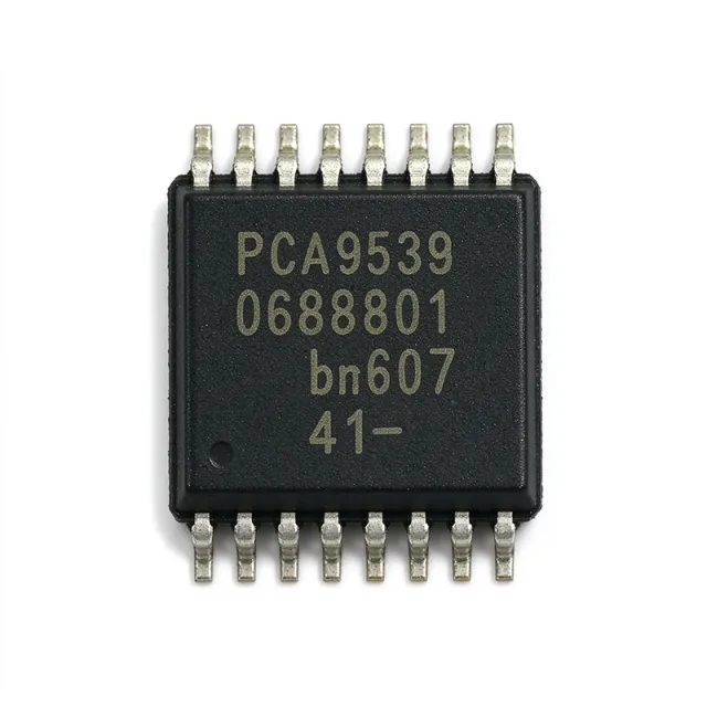
PCA9538PW - 8-Bit I2C I/O Expander | NXP | TSSOP-16
The NXP Semiconductors PCA9538PW is an 8-bit I2C-bus and SMBus general-purpose I/O expander with interrupt and reset, operating from 2.3 V to 5.5 V in a 16-pin TSSOP package. It adds eight remotely controlled digital input or output ports to a host microcontroller or processor while using the two-wire bus instead of dedicating eight GPIO pins. An I/O expander is an interface IC that extends a system’s digital input/output capability. The PCA9538 belongs to the hierarchy of GPIO expander, serial interface controller, and embedded peripheral. Its registers support configurable input, output, or high-impedance operation, while the interrupt output lets the host respond to selected port events without continuously polling all eight lines. Key features include eight general-purpose I/O lines, 2.3 V to 5.5 V operation, 400 kHz I2C/SMBus support, and dedicated interrupt and reset functions. The low-power design is useful in embedded control, sensor-interface, and power-management systems where a compact serial interface can replace several parallel host-controller pins. The device communicates through the two-line bidirectional bus using SCL and SDA. Its interrupt output provides event signaling, while reset provides a defined initialization path for the port and configuration state. These functions simplify firmware-driven GPIO expansion, particularly when the host must monitor external controls or remotely drive logic-level loads. Typical applications include ACPI power-switch control, sensor and actuator interfacing, push-button and indicator handling, and general embedded GPIO expansion. Designers should account for the selected port direction, pull-up requirements on SDA and SCL, and the electrical characteristics of every signal driven through the expander. For robust PCB implementation, place the serial-bus pull resistors close to the relevant bus nodes and keep the TSSOP routing short and clean. Review address configuration and firmware register access before operation, especially in systems with several I2C peripherals or multiple expanders on the same bus. This page consolidates the verified manufacturer and distributor information, separates confirmed specifications from data gaps, and provides practical design guidance for engineers evaluating PCA9538PW. It also records sourced drop-in alternatives where the available evidence supports pin and package compatibility.
PCA9538PWR - 8-Bit I2C I/O Expander | NXP | TSSOP-16 (Tape & Reel)
The NXP Semiconductors PCA9538PWR is an 8-bit I2C-bus and SMBus general-purpose I/O expander with interrupt and reset, operating from 2.3 V to 5.5 V in a 16-pin TSSOP package. It adds eight remotely controlled digital input or output ports to a host microcontroller or processor while using the two-wire bus instead of dedicating eight GPIO pins. An I/O expander is an interface IC that extends a system’s digital input/output capability. The PCA9538 belongs to the hierarchy of GPIO expander, serial interface controller, and embedded peripheral. Its registers support configurable input, output, or high-impedance operation, while the interrupt output lets the host respond to selected port events without continuously polling all eight lines. Key features include eight general-purpose I/O lines, 2.3 V to 5.5 V operation, 400 kHz I2C/SMBus support, and dedicated interrupt and reset functions. The low-power design is useful in embedded control, sensor-interface, and power-management systems where a compact serial interface can replace several parallel host-controller pins. The device communicates through the two-line bidirectional bus using SCL and SDA. Its interrupt output provides event signaling, while reset provides a defined initialization path for the port and configuration state. These functions simplify firmware-driven GPIO expansion, particularly when the host must monitor external controls or remotely drive logic-level loads. Typical applications include ACPI power-switch control, sensor and actuator interfacing, push-button and indicator handling, and general embedded GPIO expansion. Designers should account for the selected port direction, pull-up requirements on SDA and SCL, and the electrical characteristics of every signal driven through the expander. For robust PCB implementation, place the serial-bus pull resistors close to the relevant bus nodes and keep the TSSOP routing short and clean. Review address configuration and firmware register access before operation, especially in systems with several I2C peripherals or multiple expanders on the same bus. This page consolidates the verified manufacturer and distributor information, separates confirmed specifications from data gaps, and provides practical design guidance for engineers evaluating PCA9538PWR. It also records sourced drop-in alternatives where the available evidence supports pin and package compatibility.

PCA9539DB - 16-Bit I/O Expander, 2.3-5.5V | Texas Instruments
Texas Instruments PCA9539DB is a 16-bit I2C/SMBus low-power I/O expander operating from 2.3 V to 5.5 V, supporting a 400 kHz bus and supplied in a 24-pin SSOP package. It adds 16 general-purpose parallel I/O lines to a host microcontroller through the two-wire serial bus. An I/O expander is an interface IC that extends the usable input/output count of a microcontroller or other embedded processor. It sits in the hierarchy of semiconductor, interface IC, I/O expander, and parallel I/O controller. Rather than requiring a microcontroller to devote many pins to switches, buttons, relays, or indicators, the PCA9539DB transfers those signals over I2C while providing configurable input and output registers. The PCA9539DB provides interrupt, reset, and configuration registers. Its interrupt output is open-drain and active-low, allowing the device to signal a change in an input state without continuous software polling. Maximum standby current is 1 µA, making the device suitable for low-power embedded systems that need additional control lines while minimizing inactive-state consumption. The device connects to a two-wire bidirectional I2C or SMBus interface and operates across a 2.3 V to 5.5 V supply range. This voltage range supports both 3.3 V and 5 V system architectures. The available 400 kHz bus specification provides a practical operating rate for control-oriented peripheral expansion where throughput requirements are modest and deterministic bus behavior is more important than maximum serial bandwidth. Typical uses include expanding GPIO on a compact embedded controller, reading grouped switch or sensor inputs, driving external indicator or relay-control signals, and building a modular peripheral interface around an I2C bus. The active-low open-drain interrupt is particularly useful when the host must sleep between events and wake when an input changes. Designers should account for I2C pull-up resistors, address selection, and the electrical requirements of whichever loads connect to P0 through P15. The PCA9539DB differs from the PCA9555 because it omits the internal I/O pull-up resistors, replaces the A2 address input with RESET, and uses a different address range. This reduced loading can lower power consumption when the I/O lines are held low, but external pull-ups may be required where the application depends on them. This product record consolidates the verified manufacturer and distributor information into an engineering-focused resource covering device function, package data, sourcing links, application context, and practical replacement constraints. Only confirmed drop-in alternatives with the same package and electrical behavior are presented; functional equivalents requiring a different footprint are not mislabeled as drop-in replacements.
PCA9539DBR - 16-Bit I/O Expander | Texas Instruments | 2.3-5.5V
Texas Instruments PCA9539DBR is a 16-bit remote I2C and SMBus low-power I/O expander operating from 2.3 V to 5.5 V, with a 400 kHz bus rate, interrupt output, reset, and configuration registers in a 24-pin SSOP (DB) package. It adds 16 general-purpose input or output lines to a host controller without requiring a parallel GPIO port. An I/O expander is an interface IC that translates serial I2C or SMBus commands into parallel digital input and output signals. The PCA9539 belongs to the I/O expander class, within interface ICs and general-purpose semiconductor devices. Its purpose is to reduce microcontroller pin count while keeping peripheral control and monitoring accessible over a short two-wire serial bus. The PCA9539 provides 16 configurable I/O lines, 2.3 V to 5.5 V operation, and a maximum indicated bus speed of 400 kHz. The device also includes an interrupt output, reset support, and configuration registers. Texas Instruments describes the part as low power, and its operating temperature range is -40 °C to 85 °C for the DB package. Compared with the PCA9555, the PCA9539 removes the internal I/O pull-up resistors, replaces the A2 address input with RESET, and uses a different I2C address range. Removing the internal pull-ups can reduce current consumption when an I/O is held low, but it also requires the board designer to account for external pull-ups when the selected I/O configuration needs them. Typical uses include low-speed control-panel inputs, relay or indicator outputs, sensor and switch monitoring, keyboard-style matrix expansion, and general industrial-control systems. The serial interface is particularly useful when a controller must monitor or drive more discrete lines than its native GPIO count permits. The interrupt output can provide event-driven notification instead of continuous register polling. Designers should verify the complete DB-package pinout against the current manufacturer datasheet before PCB release. I2C bus rise time, pull-up resistance, pull-up voltage, input thresholds, output leakage, and the effect of the RESET pin must be checked in the target system. External pull-ups are particularly important because this variant does not include the PCA9555 family’s internal I/O pull-ups. This page consolidates the verified manufacturer and distributor information for PCA9539DBR, distinguishes the device from superficially similar PCA9555 and TCA9539 families, and identifies which replacement details require datasheet confirmation before a drop-in redesign.
PCA9539DW - 16-Bit 2.3-5.5V I/O Expander | Texas Instruments
The Texas Instruments PCA9539DW is a 16-bit I2C/SMBus I/O expander operating from 2.3 V to 5.5 V at up to 400 kHz, with interrupt, reset, and configuration registers in a 24-pin SOIC (DW) package. It adds 16 general-purpose serial I/O lines to a host microcontroller while minimizing package space and addressing requirements. An I/O expander is an interface IC that converts serial bus commands into parallel input or output signals. In the product hierarchy, the PCA9539 is an I/O expander, interface controller, peripheral IC, and semiconductor. It is especially useful when a microcontroller has too few pins for buttons, LEDs, relays, logic controls, or sensor-enable signals. Its I2C/SMBus connection allows the added lines to be controlled over two shared serial wires. The device provides 16 I/O pins, a 400 kHz bus clock, push-pull output capability, and low current consumption. According to the verified distributor data, output source and sink options include 10 mA and 25 mA configurations. The integrated interrupt output allows a connected processor to react to a change on an input without continuously polling the device, while reset and configuration registers support controlled startup and bus operation. The PCA9539 differs from the PCA9555 because it removes the internal I/O pull-up resistors, replaces address input A2 with RESET, and uses a different address range, as stated on the official TI product page. Removing the internal pull-ups can reduce power consumption when I/O lines remain low. The separate RESET function also provides a hardware reset path, although external pull-up or pull-down requirements must be verified against the complete electrical design. Typical uses include industrial control modules, sensor-interface boards, programmable logic controllers, remote I/O modules, instrumentation, and embedded systems requiring status LEDs, relay controls, or digital-input monitoring. The interrupt line can support efficient event-driven firmware, while the 16 parallel lines reduce the number of host-controller pins needed. Designers should confirm the 2.3 V to 5.5 V supply range, 400 kHz bus limit, I/O voltage levels, current limits, pull-up requirements, and address configuration in the manufacturer datasheet. External pull-ups on SDA and SCL and any required I/O pull resistors should be selected for the bus voltage, capacitance, and system noise environment. The host firmware should also verify register defaults before driving attached loads. This page combines verified manufacturer and distributor information, practical I/O-expander design guidance, and explicit data gaps for parameters not present in the supplied sources.
PCA9539DWR - 16-Bit 2.3-5.5V I/O Expander | Texas Instruments (Tape & Reel)
The Texas Instruments PCA9539DWR is a 16-bit I2C/SMBus I/O expander operating from 2.3 V to 5.5 V at up to 400 kHz, with interrupt, reset, and configuration registers in a 24-pin SOIC (DW) package. It adds 16 general-purpose serial I/O lines to a host microcontroller while minimizing package space and addressing requirements. An I/O expander is an interface IC that converts serial bus commands into parallel input or output signals. In the product hierarchy, the PCA9539 is an I/O expander, interface controller, peripheral IC, and semiconductor. It is especially useful when a microcontroller has too few pins for buttons, LEDs, relays, logic controls, or sensor-enable signals. Its I2C/SMBus connection allows the added lines to be controlled over two shared serial wires. The device provides 16 I/O pins, a 400 kHz bus clock, push-pull output capability, and low current consumption. According to the verified distributor data, output source and sink options include 10 mA and 25 mA configurations. The integrated interrupt output allows a connected processor to react to a change on an input without continuously polling the device, while reset and configuration registers support controlled startup and bus operation. The PCA9539 differs from the PCA9555 because it removes the internal I/O pull-up resistors, replaces address input A2 with RESET, and uses a different address range, as stated on the official TI product page. Removing the internal pull-ups can reduce power consumption when I/O lines remain low. The separate RESET function also provides a hardware reset path, although external pull-up or pull-down requirements must be verified against the complete electrical design. Typical uses include industrial control modules, sensor-interface boards, programmable logic controllers, remote I/O modules, instrumentation, and embedded systems requiring status LEDs, relay controls, or digital-input monitoring. The interrupt line can support efficient event-driven firmware, while the 16 parallel lines reduce the number of host-controller pins needed. Designers should confirm the 2.3 V to 5.5 V supply range, 400 kHz bus limit, I/O voltage levels, current limits, pull-up requirements, and address configuration in the manufacturer datasheet. External pull-ups on SDA and SCL and any required I/O pull resistors should be selected for the bus voltage, capacitance, and system noise environment. The host firmware should also verify register defaults before driving attached loads. This page combines verified manufacturer and distributor information, practical I/O-expander design guidance, and explicit data gaps for parameters not present in the supplied sources.
PCA9539PW - 16-Bit I/O Expander | NXP Semiconductors
NXP Semiconductors PCA9539PW is a 16-bit general-purpose I/O expander with I2C/SMBus connectivity, interrupt, and reset functions, designed for 2.3 V to 5.5 V operation in a 24-pin TSSOP package. It adds 16 configurable digital lines to a host controller while supporting both input and push-pull output operation. The verified distributor data identifies a 400 kHz bus and describes the device as a low-power remote I/O expander. An I/O expander is an interface IC that converts serial bus commands from a microcontroller or other host into multiple parallel digital signals. In the hierarchy, the PCA9539PW belongs to the I/O-expander class, then interface ICs, then semiconductor devices. Its purpose is to reduce direct GPIO requirements in systems that need many buttons, indicators, sensors, relays, or control lines while retaining a compact serial connection. The main feature set includes 16 general-purpose I/O lines, an interrupt output, reset support, configurable registers, and I2C/SMBus operation. The verified product description identifies the device as a 24-pin CMOS device with 16 GPIO expansion functions. Its 2.3 V to 5.5 V operating range supports both low-voltage and 5 V powered embedded systems, while the 400 kHz interface specification supports common embedded bus speeds. The interrupt and reset functions help the host avoid continuous polling when input lines change. Reset allows the host to initialize the device and its registers reliably, while the interrupt output provides an event indication for input changes. Because the exact pin names, electrical limits, and register details are not included in the supplied verified data, those values are not guessed in this record. Typical applications include ACPI power switches, sensor interfaces, push-button panels, LED indicators, and remote GPIO expansion for microcontrollers. The 16-bit organization makes it useful when a system needs more lines than a typical microcontroller package provides but does not require a large matrix keyboard or very high-current outputs. For PCB design, confirm the 24-pin TSSOP footprint and verify the bus voltage, pull-up requirements, address configuration, and pin mapping against the manufacturer datasheet before release. Do not assume that an electrically similar expander is a true drop-in replacement without checking every pin and electrical parameter. This page combines verified manufacturer and distributor descriptions, explicit data gaps, package information, application guidance, and drop-in replacement screening for the PCA9539PW.
PCA9539PW/Q900,118 - 16-Bit I2C GPIO Expander | NXP
The NXP PCA9539PW/Q900,118 is a 16-bit I2C-bus/SMBus GPIO expander with interrupt output and active-LOW reset, delivering 16 general-purpose I/O lines over a 400 kHz I2C interface in a 24-pin TSSOP (SOT361-1) package. An I/O expander is an interface IC that adds general-purpose input/output pins to a microcontroller or host processor through a serial bus such as I2C or SMBus. In the system hierarchy, it sits between the host MCU and peripheral circuitry - a power-management and interface component that relieves pin-constrained controllers of the burden of driving buttons, LEDs, switches, and sensors directly. Key features include 16 quasi-bidirectional GPIOs with 5 V tolerant I/Os, a polarity inversion register, an active-LOW open-drain interrupt output, and an external RESET pin that restores the default state without a bus power cycle. The /Q900 variant is qualified to AEC-Q100 for automotive applications and operates from 3.0 V to 5.5 V, versus 2.3 V to 5.5 V for the standard PCA9539PW. Architecturally, the PCA9539 is a CMOS slave device with four register pairs (input, output, polarity inversion, configuration) addressed via two hardware address pins A0 and A1, allowing four devices on one bus for up to 64 I/Os. Configuration registers set each pin as input (high-impedance) or output. The interrupt function flags any input state change for fast host polling, avoiding continuous bus reads. Typical applications include automotive body electronics (door modules, lighting control), keypad and switch scanning, LED drive expansion, server backplane monitoring, and industrial PLC I/O cards where MCU pin count is scarce. Design consideration: unused inputs should not be left floating; tie them to a defined level via the internal or external pull-up, and keep the I2C pull-up resistance sized for the 400 kHz bus load capacitance. This page synthesizes distributor pricing, drop-in alternatives from TI, Nexperia, and NXP standard-grade lines, plus design notes not found in the manufacturer datasheet.
PCA9539PWR - 16-Bit I/O Expander | NXP Semiconductors (Tape & Reel)
NXP Semiconductors PCA9539PWR is a 16-bit general-purpose I/O expander with I2C/SMBus connectivity, interrupt, and reset functions, designed for 2.3 V to 5.5 V operation in a 24-pin TSSOP package. It adds 16 configurable digital lines to a host controller while supporting both input and push-pull output operation. The verified distributor data identifies a 400 kHz bus and describes the device as a low-power remote I/O expander. An I/O expander is an interface IC that converts serial bus commands from a microcontroller or other host into multiple parallel digital signals. In the hierarchy, the PCA9539PWR belongs to the I/O-expander class, then interface ICs, then semiconductor devices. Its purpose is to reduce direct GPIO requirements in systems that need many buttons, indicators, sensors, relays, or control lines while retaining a compact serial connection. The main feature set includes 16 general-purpose I/O lines, an interrupt output, reset support, configurable registers, and I2C/SMBus operation. The verified product description identifies the device as a 24-pin CMOS device with 16 GPIO expansion functions. Its 2.3 V to 5.5 V operating range supports both low-voltage and 5 V powered embedded systems, while the 400 kHz interface specification supports common embedded bus speeds. The interrupt and reset functions help the host avoid continuous polling when input lines change. Reset allows the host to initialize the device and its registers reliably, while the interrupt output provides an event indication for input changes. Because the exact pin names, electrical limits, and register details are not included in the supplied verified data, those values are not guessed in this record. Typical applications include ACPI power switches, sensor interfaces, push-button panels, LED indicators, and remote GPIO expansion for microcontrollers. The 16-bit organization makes it useful when a system needs more lines than a typical microcontroller package provides but does not require a large matrix keyboard or very high-current outputs. For PCB design, confirm the 24-pin TSSOP footprint and verify the bus voltage, pull-up requirements, address configuration, and pin mapping against the manufacturer datasheet before release. Do not assume that an electrically similar expander is a true drop-in replacement without checking every pin and electrical parameter. This page combines verified manufacturer and distributor descriptions, explicit data gaps, package information, application guidance, and drop-in replacement screening for the PCA9539PWR.
PCA9541APW/01 - 2-to-1 I2C Master Selector, 16-TSSOP | NXP
The NXP PCA9541APW/01 is a 2-to-1 I2C-bus master selector with interrupt logic and reset, designed for high-reliability dual-master I2C-bus applications where system operation must continue even when one master fails or the controller card is removed for maintenance. It is housed in a 16-pin TSSOP (SOT403-1) package and supports 2 masters sharing a single downstream I2C bus, with channel 0 pre-selected at startup per the /01 variant. A 2-to-1 I2C master selector belongs to the broader family of I2C switches and multiplexers, which are themselves a subcategory of serial interface ICs used for digital inter-chip communication. The PCA9541APW/01 specifically enables bus-arbiter functionality by routing one of two upstream master controllers (e.g., a primary and a redundant back-up) onto a single downstream I2C bus segment. It sits between the master controllers and downstream peripherals, providing arbitration, fault isolation, and hot-swap capability. Key features include two upstream I2C channels (SCL0/SDA0 and SCL1/SDA1), one downstream I2C channel (SCL/SDA), an active-low RESET input, hardware-selectable channel at power-up via a startup mode pin, and bidirectional interrupt logic with separate INT0 and INT1 outputs that report which master currently controls the bus. The downstream INT_IN pin collects fault information from peripherals and propagates it upstream when enabled. The device operates from a supply voltage compatible with common 2.3V-5.5V rails and supports standard-mode and fast-mode I2C signaling. Its low on-resistance pass gates and channel-isolation logic keep bus capacitance low, ensuring clean rise/fall times even with long downstream traces. The PCA9541APW/01 variant pre-selects channel 0 at startup, while the /03 variant leaves no channel selected at startup - selection between /01 and /03 lets system designers tune the power-on behavior. Typical applications include redundant server backplanes with dual master controllers, fault-tolerant telecom equipment, hot-swappable controller cards, and industrial PLC systems where two CPUs arbitrate access to shared I2C peripherals. It is also used in RAID storage controllers and ATCA/AdvancedTCA shelf managers that require seamless master failover. When designing with this part, ensure pull-up resistors are present on the active upstream channel and the downstream bus, and follow the standard I2C impedance guidelines because the pass gates do not include internal pull-ups. Decoupling of VCC with a 100nF ceramic capacitor close to pin 16 is recommended. This page synthesizes verified distributor pricing, drop-in alternatives, and practical design notes that complement the manufacturer datasheet.
PCA9541APW/03112 - 2-to-1 I²C Master Selector w/ Interrupt | NXP
The NXP PCA9541APW/03,112 is a 2-to-1 I²C-bus master selector with interrupt logic and reset, housed in a 16-pin TSSOP (PW) package. It operates from a supply voltage of 2.3 V to 5.5 V and provides bidirectional switching between two upstream I²C masters and a single downstream I²C bus, allowing either controller to access shared target devices such as EEPROMs, sensors, and ADCs. What is an I²C master selector? An I²C master selector is a type of bus switch that routes a single shared I²C bus between two (or more) upstream controllers. It sits in the I²C signal chain between the controllers (primary and back-up) and the target devices, behaving like a 1-of-2 multiplexer that is itself controlled by the masters over a separate selection line. Master selectors are commonly used for high-reliability redundant-controller applications where continuous operation must be maintained even when one master fails or is removed for maintenance. In the component taxonomy, the part belongs to: I²C switch -> bus switch -> interface IC -> integrated circuit -> semiconductor. Key features of the PCA9541A family include low standby current, integrated interrupt logic, hardware reset input, and wide 2.3 V to 5.5 V supply compatibility that covers both 3.3 V and 5 V rails. The device supports I²C and SMBus operations and provides bus recovery capability, which is critical when one master becomes unresponsive or the I²C bus is stuck low. Two upstream buses (BUS0, BUS1) connect through the selector to a single downstream bus (BUSX), and an external pull-up resistor pulls the open-drain SDAn/SCLn lines high on each side. The PCA9541APW/03,112 architecture centers on a 1-of-2 bidirectional switch realized with pass-gate MOSFETs and an I²C-compatible control interface. Two address-select pins (A0, A1) allow up to four PCA9541A devices to coexist on the same SMBus, enabling a 1-of-4 or 1-of-8 master selection tree. The reset input (/RESET) restores the selector to a defined default state on power-up or when the active-low signal is asserted by a system supervisor. Typical applications include redundant server management on baseboard management controllers (BMCs), telecom equipment with hot-swappable controller cards, fault-tolerant industrial PLCs, and any dual-master I²C architecture where the controller or a daughter card can be removed without disrupting downstream I²C target devices. Designers also use the part to bridge two electrically isolated I²C domains through a controlled switch. When designing with this device, note that both upstream buses require their own pull-up resistors to the selected supply, and the interrupt output is open-drain and must be pulled high at the system-controller side.

PCA9543AD - 2-Channel I2C Switch with Reset | NXP
NXP Semiconductors PCA9543AD is a 2-channel bidirectional I2C-bus switch with interrupt logic and reset, operating from a 2.3 V to 5.5 V supply in a 14-pin SOIC package. It allows one upstream SCL/SDA pair to fan out to two downstream bus pairs, while the programmable control register independently enables either channel or both channels. Two active-low interrupt inputs support change detection on the downstream buses. An I2C-bus switch, also called an I2C multiplexer or I2C switch, is an interface IC that expands one controller-side bus connection into multiple target-side connections. In the product hierarchy, it belongs to the I2C interface-switch class, then to interface ICs, interface semiconductors, and broader semiconductor devices. This allows multiple devices with potentially conflicting addresses to share one physical I2C bus when their downstream ports are enabled selectively. The PCA9543AD provides two bidirectional translating channels compatible with I2C and SMBus systems. Its control register allows the upstream bus to communicate with channel 0, channel 1, or both channels. The device also includes a reset input and separate interrupt inputs for each downstream pair. These functions make it useful where downstream devices generate interrupts, wake a host controller, or must remain disconnected to prevent address conflicts. The switch's operating supply range of 2.3 V to 5.5 V accommodates both 3.3 V and 5 V system rails. Bidirectional communication is fundamental to I2C because the same SDA conductor carries command data from the controller and response data from targets, while SCL carries the clock in both directions. The package is a 14-pin SOIC measuring 0.154 inches, or 3.90 mm, in width, using a surface-mount construction. Typical uses include sensor aggregation, industrial embedded systems, communications equipment, portable electronics, and test or measurement platforms. In a multi-sensor design, the controller can enable one downstream branch at a time, communicate with the selected target, and disable that branch before accessing another device. Interrupt inputs can reduce the need for continuous polling when a downstream peripheral signals an event. Designers should verify the target's supported voltage range, bus capacitance, pull-up arrangement, and channel-isolation behavior against the manufacturer datasheet. Care is also required when connecting downstream buses with different pull-up voltages, because the switch does not inherently translate logic voltage levels. A common pitfall is assuming that a disabled channel provides complete galvanic isolation; it isolates the I2C data path but does not create independently regulated voltage domains. This product page consolidates the verified NXP device description, package information, source links, engineering-oriented application guidance, and explicitly qualified drop-in alternatives. Pricing and lead time remain unverified because the supplied distributor results did not expose numeric values, while alternative selection is limited to same-package devices that can be supported without inventing cross-reference data.