Products (21,000+)

W78L801A24PL - 24MHz 8-Bit 8051 MCU with 4KB ROM | Nuvoton
W78L801A24PL

W78L801A24PL - 24MHz 8-Bit 8051 MCU with 4KB ROM | Nuvoton

Nuvoton Technology Corporation W78L801A24PL is an 8-bit 8051-compatible microcontroller with a 24 MHz clock, 4 KB mask ROM organized as 4K x 8 bits, and a 44-LCC J-lead package. Its operating voltage range is 1.8 V to 5.5 V, making it suitable for embedded control, monitoring, and compact industrial or consumer systems. The device also provides 256 bytes of data memory and software-selectable idle and power-down operating modes for reduced power consumption. An 8-bit microcontroller is a programmable semiconductor that integrates a processor core, program memory, data memory, and peripherals into one device. The W78L801 belongs to the 8051 family, a widely used embedded-control architecture also known as an MCS-51 microcontroller. Its 4 KB mask ROM stores the fixed firmware program, while its 256-byte RAM supports variables, stack operations, and intermediate working data. Applications generally center on sequential control logic, sensor acquisition, keypad or display control, and communication interfaces. The principal operating characteristics include a maximum clock frequency of 24 MHz, an 8-bit processing architecture, 4 KB of mask-programmable ROM, and a 1.8 V to 5.5 V supply range. Two software-controlled power modes help conserve energy. Idle mode stops the processor clock while allowing supported peripheral operations to continue, whereas power-down mode stops the crystal oscillator for minimum power consumption. The external clock may also be stopped without affecting processor state according to the W78L801 datasheet. The W78L801A24PL combines conventional 8051 instruction-set compatibility with a surface-mount LCC implementation. The PL suffix denotes the 44-LCC J-lead package shown in product documentation. Its masked-program architecture is appropriate for high-volume products in which firmware is finalized before production. Because the program memory is mask ROM rather than user-programmable flash, firmware changes normally require a different programmed device rather than an in-circuit update. Typical uses include industrial controllers, appliance-control boards, instrumentation modules, building equipment, and compact embedded systems that benefit from the low-power operating modes. The 24 MHz clock provides additional processing headroom for time-sensitive control tasks, while the 8051 instruction set supports a compact software ecosystem and established development methods. System-level suitability depends on the selected external clock, memory organization, and peripheral requirements described in the datasheet. Designers should verify the exact pin functions, oscillator connections, reset behavior, and available I/O assignments against the manufacturer pin-description table before laying out a PCB. Decoupling, clock stability, exposed programming considerations, and supply sequencing also require normal mixed-signal layout practices. Because this package is a leaded LCC rather than a fine-pitch bare die, assembly planning should account for its 44 J-leads. This page combines the manufacturer-oriented device description with verified product parameters, application guidance, design cautions, and a transparent comparison of what the available technical information establishes. It helps engineers identify whether the W78L801A24PL architecture, memory configuration, clock rate, voltage range, and package align with a new embedded-control design.

RFQ Contact
W78L812A24DL - 8-Bit 24MHz 8051 MCU | Nuvoton
W78L812A24DL

W78L812A24DL - 8-Bit 24MHz 8051 MCU | Nuvoton

Nuvoton Technology Corporation W78L812A24DL is an 8-bit 8051-compatible microcontroller with 24 MHz clocking, 8 KB of flash program memory, 32 I/O pins, and a 40-pin DIP package. Its 2.4 V to 5.5 V operating range supports low-voltage embedded control systems requiring an 8-bit processor with integrated flash memory. An 8-bit microcontroller is a programmable semiconductor designed for embedded control. The W78 series combines an 8051-compatible core, program memory, data memory, and peripherals in one device. Within the embedded-control hierarchy, the W78L812A24DL is an MCU, or microcontroller unit, intended to execute firmware that monitors inputs and controls outputs in appliances, industrial equipment, and compact automation systems. Key features include 8 KB of flash program memory organized as 8K x 8, a maximum clock frequency of 24 MHz, and 32 I/O lines. EBI/EMI and UART/USART interfaces provide external-memory and serial-communication options, while integrated LED and watchdog-timer functions support status indication and system supervision. The stated 2.4 V to 5.5 V operating-voltage range also supports compatibility with common embedded power rails. The device uses an 8-bit data path and an 8051-compatible processor core. Its flash memory permits firmware to be programmed and updated without an external program-memory device, simplifying both production and maintenance. The 40-DIP mechanical package facilitates through-hole assembly and prototyping, although its larger footprint is less suitable for compact surface-mount products than smaller microcontroller packages. Typical applications include appliance controllers, LED status and sequencing systems, industrial control panels, small motor or relay interfaces, serial-connected embedded modules, and educational 8051 platforms. Designers should confirm RAM capacity, detailed timer and peripheral assignments, clock behavior, and all electrical limits against the manufacturer datasheet before creating a production PCB. For a new design, verify the 40-pin footprint, oscillator requirements, reset behavior, and available I/O functions. The DIP package simplifies breadboard and through-hole prototypes, but a high-density production design may require a different package variant and a corresponding PCB redesign. This product page consolidates the confirmed operating specifications, interface capabilities, application guidance, sourcing path, and drop-in-replacement status for engineers evaluating the W78L812A24DL.

RFQ Contact
W78L812A24FL - 8-Bit 24MHz 8051 Flash MCU | Nuvoton
W78L812A24FL

W78L812A24FL - 8-Bit 24MHz 8051 Flash MCU | Nuvoton

The Nuvoton W78L812A24FL is an 8-bit 8051-compatible Flash microcontroller with an operating clock of 24 MHz, 8 KB of Flash EPROM, 256 bytes of RAM, and a 44-pin QFP package. It operates from 2.4 V to 5.5 V and integrates four 8-bit bidirectional I/O ports, an additional 5-bit P4 port, three 16-bit timer/counters, a hardware watchdog timer, and a serial port. An 8051-compatible microcontroller is a compact embedded-control device built around the classic MCS-51 instruction set. Microcontrollers combine a CPU, program memory, data memory, timers, serial communication, and digital I/O on one integrated circuit. This integration allows control systems to monitor inputs, execute embedded software, operate timers, and exchange serial data without requiring a separate processor and supporting components. The W78L812A24FL combines 8 KB of Flash EPROM with 256 bytes of RAM, providing useful program storage for compact embedded applications. Its four 8-bit ports and dedicated P4 port offer multiple digital interfaces, while the three 16-bit timer/counters support periodic events, timing measurements, and waveform generation. The hardware watchdog timer adds an independent mechanism for recovering from stalled program execution. The 24 MHz operating frequency provides a higher instruction-processing rate than lower-frequency members of the same device family while retaining standard 8051 instruction-set compatibility. This makes the device suitable for designs based on established 8051 firmware, industrial controllers, compact instruments, appliance controls, and general-purpose embedded products requiring deterministic digital I/O. Typical uses include motor and actuator sequencing, temperature-instrument signal acquisition, keypad interfaces, LED status panels, programmable timers, and serial-connected control modules. The 2.4 V to 5.5 V operating range supports both lower-voltage and conventional 5 V designs, allowing system designers to choose the MCU around the power architecture of the finished product. PCB design should preserve stable supply decoupling near the power pins and route the oscillator, reset, and high-speed signals according to the manufacturer reference layout. Because the device offers limited RAM, firmware should use the available data memory carefully. Firmware development also benefits from 8051-compatible tools because the instruction set remains compatible with the standard 8051 architecture. This page organizes the principal electrical, memory, peripheral, package, and application characteristics of the W78L812A24FL. It also identifies same-family alternatives and explains the practical distinctions that matter when evaluating an 8051-compatible control IC for an embedded product.

RFQ Contact
W78L812A24PL - 8-bit 8051 MCU, 8KB Flash, 24MHz | Nuvoton
W78L812A24PL

W78L812A24PL - 8-bit 8051 MCU, 8KB Flash, 24MHz | Nuvoton

The Nuvoton Technology Corporation W78L812A24PL is an 8-bit microcontroller with a fully 8051-compatible instruction set, an 8 KB Flash EPROM program memory, 256 bytes of RAM and a 24 MHz operating frequency, housed in a 44-pin PLCC (PL) package with a 2.4 V to 5.5 V supply range. An 8-bit MCU is the simplest tier of the microcontroller hierarchy: MCU -> 8-bit microcontroller -> 8051 core -> embedded control IC. The W78L812 belongs to the 8051 family of single-chip computers, combining a CPU core, program memory, data memory and peripherals on one die. Because the instruction set is compatible with the standard 8051, existing 8051 assembler, C compiler and bootloader tooling can be reused without architectural changes. Key features include 8 KB of Flash EPROM instead of masked ROM, which allows field re-programming and simplifies product revisions. The device carries 256 bytes of internal RAM plus a 256-byte XRAM area, four 8-bit bi-directional bit-addressable I/O ports (P0 through P3), an additional 5-bit port P4, and three 16-bit timer/counter blocks with interrupt support for timing, pulse counting and periodic event generation. A 24 MHz oscillator gives roughly ten times the execution rate of a classic 12 MHz 8051. Because the instruction set, memory map and port structure follow the established 8051 convention, the W78L812A24PL is a natural fit for cost-sensitive embedded controllers that must run existing 8051 code. The wide 2.4 V to 5.5 V supply range allows direct operation from unregulated industrial rails, 3.3 V systems or rechargeable cells after regulation. Typical applications include smart appliances, small motor controllers, security keypads, industrial sequencers, LED lighting controllers and low-cost data acquisition front ends. Its PLCC package is a strong argument for designs that expect manual soldering or socketed prototyping rather than fully automated SMT assembly. When designing around this device, remember that Flash EPROM programming requires a dedicated programmer, and that the 44-PLCC footprint is not the same as the 40-pin DIP variant of the same family. Confirm the pinout and package drawing from the manufacturer datasheet before laying out the board, and keep decoupling close to the supply pins.

RFQ Contact
W79E217AFG - 8-bit 8051 MCU 64KB Flash 33MHz PQFP-100 | Nuvoton
W79E217AFG

W79E217AFG - 8-bit 8051 MCU 64KB Flash 33MHz PQFP-100 | Nuvoton

The Nuvoton Technology Corporation W79E217AFG is an 8-bit 8051/8052-compatible microcontroller (MCU) with a redesigned processor core that eliminates wasted clock and memory cycles, delivering up to 33 MHz core frequency and integrating 64 KB (64K x 8) of on-chip Flash program memory. Housed in a 100-pin PQFP package, it operates from a single 5 V supply (with operating voltage range per datasheet) and is positioned as a drop-in upgrade for legacy 80C51/80C52 designs that need more code space, more I/O, and embedded Flash in-system programming (ISP). A microcontroller (MCU) is a single-chip computer containing a CPU core, program memory (ROM/Flash), data memory (RAM), and peripherals such as timers, UARTs, ADC, GPIO, and interrupt controllers. The 8051 family is the most widely deployed 8-bit MCU platform in history; it sits within the broader taxonomy: 8051 -> 8-bit MCU -> microcontroller -> embedded processor -> semiconductor. The W79E217AFG belongs to Nuvoton's W79 series of industrial-grade, Flash-based 8051 derivatives aimed at motor control, instrumentation, and human-machine interface (HMI) applications. Key features of the W79E217AFG include the 33 MHz single-cycle enhanced 8052 core, 64 KB Flash, 256 + 1 KB on-chip SRAM, four 8-bit I/O ports (P0-P3), three 16-bit timers, two full-duplex UARTs, an 8-channel 10-bit ADC, an on-chip oscillator, watchdog timer, power-on reset, and brown-out detector. Industrial temperature range (-40 °C to +85 °C), PQFP-100 package with 84 usable I/O lines, and ISP via UART make it well-suited for embedded designs. Architecturally, Nuvoton re-engineered the classic 8051 pipeline to remove the original 12-clock-per-machine-cycle penalty, allowing most instructions to complete in one clock. This typically yields 2x-3x throughput vs. legacy 80C51 at the same crystal frequency, while preserving binary compatibility with standard 8051 code, assemblers, and Keil C51 toolchains. The integrated 64 KB Flash also enables field updates without external EPROM. Typical applications include industrial motor drives, AC/DC inverter controls, induction cooker controllers, smart appliance HMI panels, security alarm panels, and other 8051-based legacy designs that need to migrate from ROM/EPROM to Flash. The wide operating temperature range and large PQFP package with abundant I/O make it appropriate for human-interface boards that drive LEDs, keypads, and character/graphic LCDs. When designing with this part, ensure your ISP tool is configured for the W79E217 family boot-loader entry mode and that decoupling is placed close to the analog AVSS/AVDD pins if the 10-bit ADC is used. This page synthesizes distributor pricing, drop-in alternatives, and practical design notes not found on the manufacturer datasheet alone.

RFQ Contact
W79E352AFG - 8-bit 8051 MCU, 24MHz, 8KB Flash, 44-QFP | Nuvoton
W79E352AFG

W79E352AFG - 8-bit 8051 MCU, 24MHz, 8KB Flash, 44-QFP | Nuvoton

The Nuvoton W79E352AFG is an 8-bit 8051-family microcontroller core running up to 24 MHz, integrating 8 KB of on-chip Flash program memory and 256 bytes of SRAM, supplied in a 44-pin QFP package. It is built around an industry-standard 8051 instruction set, providing full compatibility with the MCS-51 toolchain, Keil C51, and SDCC while adding modern peripherals such as PWM, WDT, brown-out reset, low-voltage detect (LVD), and power-on reset. An 8-bit microcontroller (MCU) is a single-chip computer that integrates a CPU, program memory (ROM/Flash), data memory (RAM), and I/O peripherals into one package. The 8051 architecture, originally introduced by Intel in 1980 and now maintained by Nuvoton and others, sits within the broader hierarchy: microcontroller -> embedded processor -> digital IC -> semiconductor. The W79E352AFG belongs to Nuvoton's W79 series, optimized for cost-sensitive industrial control, home appliance, and motor drive front-ends. Key features of the W79E352AFG include up to 36 general-purpose I/O pins, multiple communication interfaces (EBI/EMI, I2C, UART/USART), four 16-bit timer/counters, hardware PWM channels, and an in-system programmable (ISP) Flash that enables firmware upgrades without removing the device from the board. Operating voltage spans 2.4 V to 5.5 V, supporting both 3.3 V and 5 V system designs with a single device. Technically, the part uses a single-cycle 8051 core that executes most instructions in 1 to 4 clocks (versus 12 in the original 8051), yielding roughly 4x to 12x higher effective MIPS than legacy designs. The integrated 4 KB auxiliary Flash area allows bootloader/ISP separation from the application code region. On-chip RC oscillator options reduce external BOM, and configurable GPIO drive strength simplifies interface to relays, MOSFETs, or 5 V peripheral logic. Typical applications include BLDC and stepper motor control (using the PWM and timer modules), home appliances (washing machines, induction cookers, microwave ovens), industrial control boards, low-end sensor hubs, and replacement of legacy 8051 designs where pin compatibility, code compatibility, and an upgrade path to ISP Flash are required. When designing in this part, reserve pin 30 (RST) for an external reset network and ensure the VDD-to-VSS decoupling is placed within 5 mm of the package. Designers moving from older Nuvoton N79E352ADG (44-DIP) parts can reuse existing firmware because the W79E352AFG shares the same SFR map. This page synthesizes distributor pricing, drop-in alternatives, package diagrams, and practical design notes that complement the official Nuvoton datasheet for engineers migrating legacy 8051 designs or evaluating the W79 series for new industrial and appliance projects.

RFQ Contact
W79E8213AKG - 8-bit 8051 MCU, 4KB Flash, 20MHz, 20-DIP | Nuvoton
W79E8213AKG

W79E8213AKG - 8-bit 8051 MCU, 4KB Flash, 20MHz, 20-DIP | Nuvoton

The Nuvoton W79E8213AKG is an 8-bit 4T-8051 microcontroller with 4KB of in-system programmable Flash EPROM, executing one instruction per clock cycle at up to 20MHz and housed in a 20-pin PDIP (DIP-20) through-hole package. It provides 128 bytes of on-chip RAM, brown-out detection, and an integrated 4-channel 10-bit ADC, targeting cost-sensitive industrial and consumer control applications where a mature 8051 core simplifies firmware reuse. An 8-bit 8051 microcontroller is a small single-chip computer based on the original Intel MCS-51 architecture, combining an 8-bit CPU, program memory, data RAM, and peripherals on a single silicon die. The 8051 family is widely classified as an MCU (microcontroller unit) within the broader category of microcontrollers, embedded processors, and finally semiconductors. Nuvoton's W79 series extends the legacy 8051 footprint with modern process technology, larger Flash densities, and ICP (In-Circuit Programming) capability for field-reprogrammability without removing the part from the board. Key features include 4KB (4K x 8) Flash program memory that supports both hardware writer and ICP modes, 128 bytes of on-chip SRAM, an operating frequency up to 20MHz, internal watchdog timer and brown-out reset for robust field operation, and a 20-pin DIP form factor that fits legacy through-hole PCB designs. The device runs across the industrial -40C to +85C temperature range, supports standard 8051 peripherals (UART, timers, GPIO), and integrates an ADC for mixed-signal sensing. At the silicon level, the W79E8213 uses a 4T (four-clock-per-machine-cycle) 8051 core, providing single-cycle instruction execution that delivers up to four times the throughput of legacy 12T 8051 derivatives at the same clock rate. The mixed program/data Flash architecture is partitioned as 4KB code space at the base address, with hardware lock bits available to protect intellectual property against unauthorized readout. Power management includes idle and power-down modes that drop supply current to microampere levels for battery-backed installations. Typical applications include home appliance controls such as rice cookers and washing machines, white goods and HVAC blower control modules, battery chargers, LED lighting controllers, security keypads, and small-format industrial control boards. The DIP-20 package and 8051 instruction set also make the W79E8213AKG a drop-in upgrade for legacy 8051 designs that need more Flash without requiring PCB rework. When designing with the W79E8213AKG, provide a 0.1uF decoupling capacitor as close as possible to VDD and a bulk capacitor on the reset pin if external reset components are used. For ISP/ICP, three of the device's GPIO pins double as the programming interface and must not be permanently pulled to a logic level during the in-circuit programming sequence. Operating voltage is typically 5V with tolerance for 3V to 5.5V operation depending on frequency. This page synthesizes distributor stock levels, parametric alternatives, ICP programming notes, and 8051 architecture context that supplement the manufacturer datasheet and help engineers select the right drop-in replacement when the W79E8213AKG reaches end-of-life.

RFQ Contact
W79E825AW - 8-Bit MCU, 16KB ISP Flash, 18 I/O Ports | Nuvoton
W79E825AW

W79E825AW - 8-Bit MCU, 16KB ISP Flash, 18 I/O Ports | Nuvoton

The Nuvoton W79E825AW (formerly Winbond W79E825A family) is an 8-bit CMOS microcontroller built around a high-speed 4T (four-clock-per-instruction) core architecture, providing 16 KB of in-system programmable (ISP) Flash program memory, 256 bytes of on-chip RAM, and 256 bytes of data-flash NVM. The device integrates 18 multi-function I/O pins, two 16-bit timer/counters, 13 interrupt sources arranged in four priority levels, one Enhanced full-duplex UART, one I2C bus interface, a programmable Watchdog Timer, four channels of 10-bit PWM, and a 4-channel multiplexed 10-bit A/D converter. According to the manufacturer datasheet, the on-chip oscillator and clock circuitry eliminate the need for an external crystal on many designs, while a selectable instruction cycle architecture balances throughput and power consumption. The W79E825AW shares its fundamental die with the broader W79E82xA family, and is offered in the 'AW' suffix package code. A microcontroller (MCU) is a single-chip computer that integrates a CPU, non-volatile program memory, volatile RAM, and peripheral interfaces into one package; 8-bit MCUs such as the W79E825AW remain widely used in cost-sensitive embedded designs where the processing workload (sensing, key handling, simple state machines, motor pulse trains) fits comfortably within an 8-bit data path. Within the broader semiconductor taxonomy, an MCU belongs to the microcontrollers sub-category of Integrated Circuits, sitting above Logic ICs and beneath microprocessors in capability. The 4T core architecture positions the W79E825AW for one-instruction-per-four-clock operation, providing up to several MIPS per MHz depending on the selected clock source. Key features of the W79E825AW include ISP Flash that supports in-application firmware updates without removing the part from the board, a configurable 4-/2-channel 10-bit PWM block for motor or LED control, a 10-bit ADC that can be routed to multiple I/O pins, and a Brown-out / Watchdog combination for unsupervised recovery from power or code faults. The four-level interrupt controller lets time-critical events preempt background tasks, and the Enhanced UART supports 9-bit address-mode communications for RS-485 multi-drop networks. Typical applications include white-goods control boards, low-end motor drives, simple sensor hubs, IR remote transceivers, and consumer-electronic user-interface modules. The 18 I/O budget covers keypad scanning, LED driving, and small display interfaces without external expanders. When designing with this part, leave at least one UART accessible as a serial debug / ISP window and verify the ISP entry sequence against the In-System Programming section of the manufacturer datasheet to avoid lock-out conditions.

RFQ Contact
W79E9781AKG - 8-bit MCU 64KB Flash | Nuvoton | Industrial
W79E9781AKG

W79E9781AKG - 8-bit MCU 64KB Flash | Nuvoton | Industrial

The Nuvoton W79E9781AKG is an 8-bit Turbo 51-compatible microcontroller with 64 KB of in-system programmable Flash, 1.25 KB SRAM, and a wide operating voltage range, packaged in a 128-pin LQFP. It integrates a 10-bit ADC, four 16-bit timers, a watchdog timer, a full-duplex hardware UART, an I2C/SPI master interface, and a built-in brown-out detector for industrial-grade reliability. An 8-bit microcontroller (MCU) is a microprocessor-on-a-chip that integrates a CPU, program memory, data RAM, and peripherals into a single IC. The 8-bit architecture is optimized for cost-sensitive, low-power, deterministic control tasks; in the system hierarchy an MCU sits between discrete logic ICs and 32-bit microprocessors, providing firmware-driven I/O handling, sensor interfacing, and protocol conversion. Nuvoton's W79 family extends the legacy 8051 instruction set with Turbo-MCU enhancements, doubling the standard clock-per-instruction cycle for higher throughput at the same crystal frequency. Key features include 64 KB of in-system programmable (ISP) Flash allowing field firmware updates via UART, an operating voltage range of 2.4V to 5.5V that supports both 3.3V and 5V rails, and an industrial-grade operating temperature of -40C to +85C. The on-chip 10-bit ADC provides up to 8 analog input channels, while the four 16-bit timer/counters support PWM generation, capture, and event counting. A dedicated hardware watchdog and brown-out reset circuit protect against code lockup and unstable supplies. The W79E9781AKG uses the standard 8051 instruction set with Nuvoton Turbo-MCU extensions, allowing one machine cycle per clock rather than the original 12, while preserving binary compatibility with legacy 8051 firmware. The device's ISP mechanism boots from a ROM-resident bootloader that re-programs the Flash via the UART pins, eliminating external programming hardware during prototyping and field service. Typical applications include industrial control panels, home appliance main boards, motor control BLDC drivers, smart meter data concentrators, and point-of-sale terminals. The integrated ADC, timers, and UART let designers replace multiple discrete components with a single chip, shrinking BOM cost and PCB area. When designing with this device, plan ISP access by routing the UART pins to a header or optocoupler-isolated connector. Use the brown-out detector level matched to the lowest reliable rail voltage (typically 2.7V for 3.3V systems) to prevent Flash corruption during power-down events. This page consolidates distributor pricing, package-level drop-in alternatives, and engineering design notes that go beyond the manufacturer datasheet, supporting faster component selection and risk-aware substitution decisions.

RFQ Contact
W83L951ADG - Mobile Keyboard Embedded Controller | Winbond
W83L951ADG

W83L951ADG - Mobile Keyboard Embedded Controller | Winbond

The Winbond W83L951ADG is a CMOS mobile keyboard and embedded controller fabricated in a 128-pin LQFP (PQFP128) surface-mount package, integrating an 8051-compatible microcontroller core with keyboard scanning, embedded controller, and system management functions for notebook and mobile computing platforms. It was originally produced by Winbond Electronics Corporation, whose embedded controller product line later transferred to Nuvoton Technology, which is why the same MPN appears under both Winbond and Nuvoton branding in distributor catalogs. An embedded controller (EC) is a specialized microcontroller in the power-management hierarchy of a computer system: it is a dedicated, always-on processor that supervises the keyboard matrix, power sequencing, battery charging supervision, thermal sensing, and low-level I/O even while the main CPU is asleep or off. In laptop and mobile designs the EC is the first silicon to wake and the last to sleep, making its firmware and electrical behavior critical to system reliability. Key features of the W83L951ADG include the 8051-derived instruction-set core with embedded firmware memory, an integrated keyboard controller (KBC) compatible with legacy PC/AT keyboard and PS/2 interfaces, general-purpose I/O for board-level control, and low-power CMOS operation suited to battery-powered systems. The device communicates with the host chipset over an LPC (Low Pin Count) style interface used in legacy EC architectures, allowing ACPI-compliant power management event handling. Architecturally, the part follows the classic Winbond/Nuvoton EC family: a single-chip design combining the CPU, program memory, RAM, keyboard matrix scanner, host interface, timers, and GPIO banks, minimizing external component count in dense mobile motherboards. The LQFP-128 package with 0.4 mm lead pitch provides the pin count needed for large keyboard matrix scanning plus numerous GPIO without a larger footprint. Typical applications include laptop and notebook keyboard controllers, embedded system management in x86 mobile platforms, tablet and portable device keyboard scanning, and industrial legacy designs that require PC/AT-compatible KBC functionality. Design consideration: because this device is long past active production, verify remaining authorized stock and confirm firmware compatibility before committing it to a new build; legacy designs should plan a migration path to current Nuvoton EC families. This page synthesizes distributor sourcing data, datasheet availability, drop-in variant information, and practical obsolescence guidance not consolidated in the manufacturer datasheet.

RFQ Contact
WPC8763LDG - Embedded Controller IC QFP-128 | Winbond
WPC8763LDG

WPC8763LDG - Embedded Controller IC QFP-128 | Winbond

The Winbond Electronics WPC8763LDG is a specialized embedded controller (EC) integrated circuit supplied in a 128-pin QFP surface-mount package, designed primarily for notebook PC and mobile-system platform management applications such as keyboard scanning, power sequencing supervision, and thermal/fan control. An embedded controller is a specialized microcontroller that operates semi-independently of the host CPU to manage low-level platform functions. In the PC system hierarchy, the EC sits below the main CPU and chipset (PCH) as a power-management IC tier: it handles keyboard matrix scanning, battery charging supervision, thermal monitoring, fan speed control, and lid/power-button events, typically following Intel or AMD platform EC firmware specifications such as those used with ACPI and eSPI/KBC interfaces. The WPC8763LDG belongs to Winbond's WPC876x family of embedded controllers, which integrates an 8-bit or proprietary MCU core with on-chip flash/ROM program memory, keyboard controller (KBC) logic, GPIO, PWM channels for fan control, and ADC inputs for thermal and voltage monitoring. Key differentiating features of this family include the high GPIO count required for notebook keyboard matrices, integrated PWM fan controllers that reduce external component count, and low standby power consumption for battery-operated systems. The 128-pin QFP package provides sufficient I/O for a full notebook EC implementation on a single chip. Architecturally, EC devices like the WPC8763LDG combine a low-power MCU core, a shared RAM region, dedicated peripheral blocks (PS/2 keyboard interface, SMBus/I2C masters for battery and thermal IC communication, pulse-width modulators, and watchdog timers), and boot ROM. Firmware executes from internal non-volatile memory, and the EC communicates with the chipset over LPC or eSPI buses depending on platform generation. Typical applications include laptop and notebook motherboard EC functions, keyboard/mouse controller emulation (PS/2 KBC/Mouse), battery charging management in coordination with a charger IC, thermal and acoustic (fan) management, and general-purpose GPIO expansion in portable and industrial embedded systems. A key design consideration is firmware compatibility: the EC must run BIOS-coordinated firmware, so replacing this device requires both hardware pin compatibility and firmware/toolchain support - verify code image compatibility before any substitution. This page synthesizes distributor stock and pricing data, package information, and sourcing guidance not consolidated in the manufacturer's public datasheet listing.

RFQ Contact
XC2287M104F80LRABKXUMA1 - 16/32-Bit 80MHz 832KB Flash MCU | Infineon
XC2287M104F80LRABKXUMA1

XC2287M104F80LRABKXUMA1 - 16/32-Bit 80MHz 832KB Flash MCU | Infineon

The Infineon XC2287M104F80LRABKXUMA1 is a 16/32-bit C166SV2 XC22xxM family microcontroller integrating a CISC/DSP/RISC processing core running at 80 MHz with 832 KB of on-chip Flash and 58 KB RAM, supplied in a 144-pin PG-LQFP-144-4 package with exposed pad. It targets automotive and industrial powertrain, body, and chassis applications requiring deterministic real-time response combined with DSP-grade signal processing throughput on a single die. A microcontroller (MCU) is a single-chip processing subsystem that integrates a CPU core, program and data memory (Flash, ROM, RAM), peripheral interfaces (ADC, timers, communication buses), and power management. Within the broader semiconductor taxonomy, MCUs sit inside Embedded Processors and Controllers, alongside microprocessors (MPUs) and system-on-chips (SoCs); they are typically selected over MPUs when deterministic latency, low power, and tight BOM integration matter more than raw application-processor performance. The C166S V2 core inherits the classic C166 instruction set with DSP extensions and RISC-like single-cycle execution, placing this part in the legacy 16-bit automotive MCU segment alongside derivatives such as the XC2764X and XC2336D families. Key features of the XC2287M104F80LRABKXUMA1 include 832 KB program Flash, 58 KB SRAM, an on-chip 10-bit ADC with up to 118 channels per the JLCPCB catalog listing, an operating voltage range of 3.0 V to 5.5 V, and an industrial-grade temperature range of -40 °C to +125 °C. The 80 MHz C166S V2 core is paired with a MAC (multiply-accumulate) unit, enabling single-cycle DSP operations suitable for sensor signal conditioning and field-oriented motor control. The LQFP-144 package with exposed pad supports an external thermal pad for improved heat dissipation in power-dense automotive ECUs. Architecturally, the XC2287M pairs two independent on-chip peripherals: a MultiCAN module with up to five CAN nodes for automotive network integration, plus USART, SSC, and I2C interfaces for sensor and actuator links. The integrated Peripheral Event Controller (PEC) enables DMA-style peripheral-to-memory transfers, allowing CPU background time for high-rate ADC-to-memory capture without interrupt overhead. Combined, this peripheral mix makes the part appropriate for multi-bus automotive ECUs where CAN-FD-class networking, deterministic ADC sequencing, and DSP-class signal processing are all required on one chip. Typical applications include automotive body control modules (BCM), electric power steering (EPS) motor controllers, HVAC blower/temperature control, instrument cluster signal processing, and industrial servo/motor control. Designers also deploy the XC2287M in industrial inverter front-ends and CAN-connected sensor hubs. When selecting this part, verify that your toolchain supports the C166S V2 instruction set and that the chosen compiler (e.g., Keil C166, TASKING, iSystem winIDEA) generates code for the C166S V2 core; pin-compatible Infineon XC2286/2288 family members can be substituted with only Flash capacity differences for shorter code footprints. The exposed pad must be soldered to the PCB ground plane for thermal and electrical performance. This page synthesizes distributor pricing, same-brand drop-in alternatives, and practical design notes that complement, but do not replace, the Infineon XC228xM datasheet.

RFQ Contact
XC68HC912D60CFU8-FR - 16-Bit 60KB Flash MCU | NXP
XC68HC912D60CFU8-FR

XC68HC912D60CFU8-FR - 16-Bit 60KB Flash MCU | NXP

The NXP XC68HC912D60CFU8-FR is a 16-bit M68HC12 embedded microcontroller with 60 KB of flash memory, CPU12 processing, and connectivity described as CANbus, MI Bus, SCI, and SPI. The device is supplied in an 80-pin QFP package, with the verified ordering information identifying the XC68HC912D60CFU8 variant and the -FR ordering suffix. Its 60 KB flash figure identifies it as a program-memory-oriented MCU for embedded control systems requiring deterministic peripheral access and embedded software integration. An MCU is a semiconductor device that combines a processor core, program memory, data memory, peripherals, and communication interfaces on one integrated circuit. The M68HC12 family belongs to the embedded-microcontroller hierarchy, where a CPU executes firmware, reads inputs, controls outputs, and manages communication links. The XC68HC912D60CFU8-FR is positioned for industrial and embedded applications where CANbus, serial, SPI, or related interfaces are useful system building blocks. The verified product information identifies the MCU as using a 16-bit CPU12 core, 60 KB flash, 80-QFP packaging, and connectivity including CANbus, MI Bus, SCI, and SPI. The available search data does not provide verified RAM size, maximum CPU frequency, supply voltage, ADC specifications, timer details, operating-temperature grade, or absolute pin-level timing values for this exact suffix, so those parameters remain unspecified rather than inferred. The NXP datasheet search result also identifies related XC68HC912D60 package and temperature-grade orderings, which should be used as a basis for checking the final ordering code. Typical design roles include embedded motor and industrial controllers, CAN-connected equipment, serial-device control, SPI peripheral coordination, and compact control platforms requiring a 16-bit MCU architecture. The -FR suffix is an ordering designation associated with the supplied part number; package, temperature, and lead-finish details should be confirmed against the manufacturer ordering information before production release. Designers should preserve the exact 80-pin QFP footprint and verify pin multiplexing, power, ground, clock, debug, and communication assignments from the datasheet before layout release. Review the required CANbus, SCI, SPI, and MI Bus transceiver or peripheral connections, and confirm that the selected firmware, development tools, and memory map match the exact device variant. This page consolidates verified distributor and manufacturer-linked search data, the available datasheet references, ordering information, and engineering-selection guidance for engineers evaluating XC68HC912D60CFU8-FR.

RFQ Contact

XC7Z020-2CLG484I - Zynq-7000 SoC 85K Logic Cells | AMD
XC7Z020-2CLG484I

XC7Z020-2CLG484I - Zynq-7000 SoC 85K Logic Cells | AMD

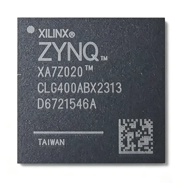
The AMD XC7Z020-2CLG484I is a Zynq-7000 All Programmable SoC (AP SoC) integrating a dual-core ARM Cortex-A9 MPCore processor with an Artix-7 class FPGA fabric in a single 484-ball CSPBGA (19x19 mm) package. The processor subsystem runs at up to 766 MHz with CoreSight debug, while the programmable logic provides 85,000 logic cells, 53,200 LUTs, 106,400 flip-flops, 220 DSP slices, and 4.9 Mb of block RAM. A System on Chip (SoC) is an integrated circuit that consolidates processor, memory controllers, peripherals, and programmable hardware on a single substrate. The Zynq-7000 family pairs an ARM-based processing system (PS) with programmable logic (PL) over high-bandwidth AXI interfaces, reducing board space, power, and system complexity versus discrete processor-plus-FPGA solutions. Key features include a DDR3/DDR3L memory controller with ECC, USB 2.0, Gigabit Ethernet, and support for I/O voltages of 1.2V, 1.5V, 1.8V, 2.5V, and 3.3V. The -2 speed grade supports up to 766 MHz PS operation and 200 MHz+ fabric clocking. The industrial temperature grade (-40C to +100C) targets harsh environments. Architecturally, the PS and PL are independent power domains with defined sequencing requirements (VCCINT, VCCAUX, VCCBRAM, VCCO). The device supports partial reconfiguration, allowing dynamic PL updates while the PS continues running. The memory controller delivers robust DDR3/DDR3L with ECC for industrial and automotive-class designs. Typical applications include motor control, industrial automation, software-defined radio, video processing, and embedded vision. The device suits real-time processing with hardware acceleration, such as machine vision and high-speed data acquisition. Design consideration: ensure correct power-rail sequencing and provide a configuration source (QSPI flash) and PS clock; refer to the Zynq-7000 TRM (UG585) for detailed guidance. Pricing from $60.07 (LCSC, as of 2026-08-29).

USD $49.00 Contact
XC8664FRIBEKXUMA1 - 8-bit XC800 MCU, 16KB Flash, 38-TSSOP | Infineon
XC8664FRIBEKXUMA1

XC8664FRIBEKXUMA1 - 8-bit XC800 MCU, 16KB Flash, 38-TSSOP | Infineon

The Infineon XC8664FRIBEKXUMA1 is an 8-bit microcontroller built around the XC800 family 8051-compatible CISC core, integrating 16 KB of on-chip Flash memory, 16 KB (16K x 8) program Flash, and 38-pin TSSOP packaging. It operates from a wide supply range of 2.5 V / 3.3 V / 5 V and runs the 8051 core up to 86 MHz (with peripheral domain scaling at 26.67 MHz per the Hotenda listing). According to the manufacturer datasheet, this IC is the first product of a new and advanced 8-bit uC family (XC8oo family), combining a high-performance 8051 core with on-chip Flash memory and powerful on-chip peripherals. An 8-bit microcontroller (MCU) is a single-chip computer that integrates a CPU, RAM, non-volatile program memory, and peripherals such as timers, ADC, and communication interfaces. The 8051 CISC architecture, originally introduced by Intel in 1980, remains one of the most widely deployed embedded cores worldwide and underpins the hypernym hierarchy 8051 -> 8-bit MCU -> microcontroller -> embedded processor -> semiconductor. The XC8664FRIBEKXUMA1 belongs to Infineon's XC866 sub-family, which is targeted at cost-sensitive industrial and automotive body applications requiring deterministic 8-bit performance. Key differentiating features include a TSSOP-38 footprint with gull-wing leads, automotive temperature grade, integrated 16 KB Flash that supports in-application programming, an on-chip ADC and Capture/Compare Unit (CCU6), and a MultiCAN node for automotive networking. The 86 MHz core clock enables high-throughput bit-manipulation routines typical of motor-control and sensor-interface code, while the wide 2.5 V to 5 V supply range simplifies integration into 3.3 V and 5 V mixed-rail systems without external level shifters. The architecture pairs the standard 8051 instruction set with an XC800-specific peripheral set, including the MultiCAN module, the CCU6 motor-control timer, and a 10-bit ADC with up to eight channels. The wide operating voltage window (2.5 V to 5 V) is a defining trait of the XC8oo family and removes the need for separate voltage regulators in many 3.3 V or 5 V designs. Internal PLL, oscillator, and brown-out circuitry further reduce the external BOM. Typical applications include automotive body electronics, sensor interface modules, low-end motor control, and industrial control. The on-chip MultiCAN node makes the part particularly attractive for in-cabin nodes communicating over a CAN bus at 100 kbit/s to 1 Mbit/s. Designers should note that this part is in the older XC8xx family; current Infineon 8-bit roadmaps have shifted to the XC2000 and AURIX families, so lifecycle planning is recommended before committing to long-life designs.

RFQ Contact
XMC1100-T016X0064AAXUMA1 - 32MHz Cortex-M0 64KB MCU | Infineon
XMC1100-T016X0064AAXUMA1

XMC1100-T016X0064AAXUMA1 - 32MHz Cortex-M0 64KB MCU | Infineon

Infineon Technologies XMC1100-T016X0064AAXUMA1 is a 32-bit Arm Cortex-M0 microcontroller operating at 32 MHz, with 64 KB of flash memory and a 16-pin PG-TSSOP-16-8 package. It is designed for general-purpose industrial and consumer applications where an efficient 32-bit MCU, compact footprint, and embedded analog control are useful in the same device. A microcontroller is a programmable system-on-chip that integrates a processor core, nonvolatile program memory, volatile data memory, peripherals, and interface circuitry into one component. The XMC1100 belongs to the XMC1000 family of Cortex-M0 microcontrollers, a low-complexity branch of 32-bit embedded processing. This family targets entry-level industrial and consumer designs and can support cost-sensitive replacements for conventional 8-bit and 16-bit microcontroller systems. The target device combines a 32 MHz Arm Cortex-M0 core with 64 KB of flash and a six-channel ADC. Its 32-bit architecture supports efficient handling of firmware, control loops, communications, and general-purpose peripheral tasks while retaining a compact 16-pin package. The six-channel ADC provides multiple analog input paths for sensing applications, allowing several physical measurements to be handled by one microcontroller rather than requiring separate analog front-end devices. The XMC1100 series is positioned for applications that require basic embedded control without the memory and peripheral complexity of a higher-end microcontroller. Its operating concept combines deterministic embedded execution with integrated analog acquisition and serial peripherals. The 64 KB flash configuration also leaves a defined code-storage footprint for compact control firmware, bootloader functions, and application-specific routines. Typical uses include industrial sensor modules, compact motor-control nodes, small appliance controllers, building equipment, communication peripherals, and consumer products that need several analog inputs. The part is especially relevant where board area is constrained but a 16-pin package can still provide access to the required digital and analog signals. A suitable application should map every required signal, peripheral, power rail, and programming interface to the available TSSOP-16 footprint before design release. The principal design consideration is pin-budget allocation. In a 16-pin package, power pins, ground connections, clocking, programming, reset, and communication signals can constrain the number of application I/O pins. Place the decoupling capacitors adjacent to their supply pins, route programming and debug access for reliable field updates, and confirm signal directions and analog limits against the manufacturer pin-description table before laying out the PCB. This page consolidates the XMC1100 device identity, verified manufacturer documentation, package information, replacement options, and practical design guidance. It also distinguishes exact memory configurations and silicon-step options so engineers can evaluate drop-in choices without confusing a lower-memory variant or a different revision with an equivalent 64 KB AA-step device.

RFQ Contact
XMC1100Q024F0008ABXUMA1 - 32MHz Cortex-M0 MCU | Infineon
XMC1100Q024F0008ABXUMA1

XMC1100Q024F0008ABXUMA1 - 32MHz Cortex-M0 MCU | Infineon

Infineon Technologies XMC1100Q024F0008ABXUMA1 is a 32-bit ARM Cortex-M0 industrial microcontroller operating at 32 MHz, with 8 KB of flash memory and a PG-VQFN-24-19 package. It is designed for cost-sensitive embedded control applications that require deterministic real-time performance, mixed-signal interfacing, and compact industrial packaging. A microcontroller integrates a processor core, nonvolatile program memory, volatile data memory, and peripherals into one semiconductor device. The XMC1100 belongs to the XMC1000 family of industrial ARM Cortex-M0 MCUs. This product type combines low-power embedded processing with serial communications, timing, and analog input capabilities, making it suitable for sensors, actuators, communications modules, and compact industrial controllers. The principal specifications are a 32 MHz ARM Cortex-M0 core, 8 KB of flash memory, 16 KB of RAM, and operation across a 1.8 V to 5.5 V supply range. The device also provides mixed-signal acquisition resources, including a 12-bit ADC, together with I2C, LIN, SPI, UART, and USART interfaces. An internal 16 MHz oscillator supports clock generation without requiring an external crystal for suitable designs. The XMC1100 architecture is intended for both event-driven and periodic control. Its peripheral set allows software to service communication interfaces while timers organize deterministic tasks and the ADC measures analog quantities. Alternate port-output functions can be assigned through the Pn_IOCR.PC register, providing flexible signal routing between general-purpose pins and peripheral outputs. The exact pin-level functions for this ordering code are defined in the Infineon datasheet pin table. Typical uses include industrial sensor nodes, LIN-connected actuators, low-cost data acquisition modules, building automation controls, and compact communications equipment. The 12-bit ADC supports measurements of analog sensors, while the available serial interfaces simplify connection to external transceivers, displays, memories, and industrial peripherals. A 32 MHz Cortex-M0 core provides useful processing headroom without requiring a higher-cost application processor. For PCB design, use the PG-VQFN-24-19 land pattern, connect the ground and supply pins according to the datasheet, and place decoupling capacitors close to their associated pins. Pay particular attention to exposed-pad connection and analog-ground routing when using the ADC. Firmware developers should also configure unused pins, validate peripheral pin multiplexing, and account for startup behavior before enabling external circuitry. This product overview combines the Infineon ordering information, device parameters, interface details, practical application guidance, and drop-in alternatives into an engineering-focused reference. It also highlights the exact distinctions that matter when evaluating firmware compatibility, PCB reuse, memory capacity, and mixed-signal performance.

RFQ Contact
XMC1100Q024F0064ABXUMA1 - 32MHz Cortex-M0 MCU | Infineon
XMC1100Q024F0064ABXUMA1

XMC1100Q024F0064ABXUMA1 - 32MHz Cortex-M0 MCU | Infineon

Infineon XMC1100Q024F0064ABXUMA1 is a 32-bit Arm Cortex-M0 microcontroller operating at 32 MHz, with 64 KB of Flash memory and 16 KB of SRAM in a 24-pin VQFN package. The device is designed for cost-sensitive embedded control systems requiring deterministic peripheral access, compact packaging and low system complexity. Its supply range is 2 V to 24 V, while the industrial ordering designation supports use in industrial equipment, controls and embedded automation. A microcontroller is a programmable semiconductor that integrates a processor core, memory, communication peripherals and general-purpose I/O into one device. The XMC1000 series belongs to the hierarchy of 32-bit microcontroller, embedded processor, embedded controller and programmable semiconductor. The Arm Cortex-M0 core uses a compact instruction set and interrupt-driven architecture suited to real-time control, sensor monitoring and basic human-machine-interface applications. Key characteristics include a 32 MHz clock, 64 KB of Flash for firmware, 16 KB of SRAM for working memory and a compact VQFN-24 package measuring 4 mm by 4 mm. The 24-pin VQFN configuration includes an exposed pad and is suitable for space-constrained boards requiring high mounting density. The industrial XMC1100-Q024F0064-AB ordering code identifies this function and package combination. The XMC1000 architecture is centered on the Cortex-M0 processor and dedicated peripheral modules. Port pins can provide alternate output functions selected through the port input/output control register, allowing communication and timing functions to share a limited pin count. This integration supports compact designs that require several peripheral functions without moving to a larger package. Exact peripheral allocations and electrical limits should be selected against the pin-description and electrical-characteristics tables in the manufacturer datasheet. Typical applications include industrial sensor controllers, compact motor-control modules, building automation nodes, appliance control boards, low-cost communication equipment and general embedded monitoring systems. The 64 KB Flash capacity is appropriate for moderate firmware sizes, while 16 KB of SRAM allows useful working buffers without external memory in many cost-sensitive products. PCB design should preserve the exposed-pad thermal and electrical requirements of the VQFN-24 package. Place the device according to the manufacturer land pattern, route sensitive interfaces away from fast-edge signals and follow the datasheet recommendations for supply decoupling and exposed-pad soldering. This product page combines the ordering information, package details, memory configuration, compatible ordering references, application guidance and practical design considerations into one engineering-focused reference for evaluating the XMC1100Q024F0064ABXUMA1.

RFQ Contact
XMC1100Q040F0064ABXUMA1 - 32MHz Cortex-M0 MCU | Infineon
XMC1100Q040F0064ABXUMA1

XMC1100Q040F0064ABXUMA1 - 32MHz Cortex-M0 MCU | Infineon

Infineon Technologies XMC1100Q040F0064ABXUMA1 is an industrial 32-bit ARM Cortex-M0 microcontroller operating at 32 MHz, with 64 KB flash memory, 16 KB SRAM, and a 40-pin PG-VQFN-13 package. It targets general-purpose embedded applications that require deterministic control performance, compact size, and a price-sensitive microcontroller platform. A microcontroller is a programmable semiconductor containing a processor core, memory, and integrated peripherals on one chip. The XMC1100 belongs to the XMC1000 family of industrial ARM Cortex-M0 devices, placing it within the hierarchy of embedded processor, general-purpose microcontroller, and industrial control semiconductor. Its Cortex-M0 architecture supports efficient event-driven control while simplifying firmware development for motor, sensing, communications, and automation systems. The device combines a 32 MHz clock with 64 KB of flash and 16 KB of SRAM. The 2 V to 40 V operating range supports industrial systems connected to wide-range supply rails, while the -40°C to 85°C temperature range covers demanding ambient environments. The PG-VQFN-40-13 package reduces board area and includes an exposed pad that requires careful PCB thermal-design practices. The XMC1100 series is designed for price-sensitive applications requiring current embedded functionality. Its 64K x 8 flash organization provides deterministic on-chip program storage, while 16 KB of SRAM supports working data, stack space, and buffering. Port functions can be mapped to alternate output functions, with individual port pins supporting seven alternate output functions according to the Infineon XMC1100 datasheet. Typical applications include industrial sensor nodes, compact motor controllers, building and automation modules, power-conversion controllers, and communications equipment. The combination of a 32 MHz Cortex-M0 core, wide supply range, and compact 40-pin package makes the XMC1100 particularly suitable for cost-sensitive equipment requiring local control without a high-performance processor or large external memory. PCB design should follow the manufacturer land-pattern and exposed-pad requirements. Keep sensitive signal routing away from switching nodes, provide low-impedance supply and ground connections, and thermally couple the exposed pad to an adequate ground plane. Firmware must also account for the device's memory limits and use interrupt-driven or event-driven control where deterministic response is important. This page organizes the XMC1100Q040F0064ABXUMA1 specifications, package information, sourcing options, design guidance, and verified drop-in alternatives. It also distinguishes confirmed pin and electrical characteristics from information that requires confirmation against the manufacturer datasheet, helping engineers plan a reliable embedded design.

RFQ Contact
XMC1100T016F0016ABXUMA1 - 32MHz ARM Cortex-M0 MCU | Infineon
XMC1100T016F0016ABXUMA1

XMC1100T016F0016ABXUMA1 - 32MHz ARM Cortex-M0 MCU | Infineon

The Infineon XMC1100T016F0016ABXUMA1 is a 32-bit ARM Cortex-M0 microcontroller operating at 32 MHz with 16 KB of Flash program memory in a 16-pin PG-TSSOP package. Designed for price-sensitive industrial control applications, it combines a compact footprint with the XMC1000 series architecture and a broad set of embedded peripherals. A microcontroller is a programmable system-on-chip that integrates a processor core, memory, clock circuitry, and peripherals such as timers, communication interfaces, and analog-to-digital converters. The ARM Cortex-M0 core provides a deterministic instruction set suitable for event-driven control. Within the device hierarchy, this MCU belongs to the XMC1000 family, combines ARM Cortex-M0 processing with embedded analog and timer resources, and targets industrial real-time control designs. Principal features include a 32 MHz operating frequency, 16 KB of Flash memory organized as 16K by 8, and a 32-bit processor architecture. The 16-pin TSSOP-16 package supports compact PCB layouts while retaining port multiplexing capabilities. The XMC1100 platform is designed for demanding yet cost-sensitive applications, and its analog acquisition and timer resources can support control loops, signal acquisition, and peripheral communication in the same device. The XMC1100 device family uses configurable port multiplexing so individual pins can carry several alternate functions, including up to seven alternate output functions mapped to a port pin. This flexibility helps designers optimize pin assignment on a small 16-pin package. Clocking and timer resources organize real-time tasks, while the microcontroller's control-oriented peripherals reduce the need for separate discrete components. Typical uses include industrial sensor controllers, compact motor and actuator control nodes, LIN-connected automotive subsystems, small power-conversion controllers, and embedded measurement modules. The device is particularly suitable when a 32 MHz control loop, fast peripheral access, and 16 KB of code storage are sufficient for the application. Firmware development is supported by the ARM Cortex-M0 ecosystem and Infineon XMC tooling. Designers should allocate decoupling capacitors, route sensitive analog inputs away from fast switching nodes, and confirm the selected port's alternate-function mapping in the manufacturer datasheet. Before production release, review the errata sheets for the AB step and verify low-power wake-up, timer, and serial-interface behavior against the final board layout and firmware configuration. This page consolidates the Infineon ordering information, datasheet characteristics, distributor availability references, drop-in options, and practical integration guidance into one engineering-focused resource. It also distinguishes confirmed pin-compatible alternatives from parts that merely share similar specifications.

RFQ Contact
XMC1100T016F0064ABXUMA1 - 32MHz 64KB Cortex-M0 | Infineon
XMC1100T016F0064ABXUMA1

XMC1100T016F0064ABXUMA1 - 32MHz 64KB Cortex-M0 | Infineon

The Infineon Technologies XMC1100T016F0064ABXUMA1 is a 32-bit ARM Cortex-M0 microcontroller operating at 32 MHz, with 64 KB of Flash memory and 16 KB of RAM in a PG-TSSOP-16-8 package. It targets compact, cost-sensitive embedded systems that require deterministic control, efficient peripheral integration, and a small surface-mount footprint. The 16-pin package supports space-constrained industrial, communications, appliance, and consumer-control designs. An ARM Cortex-M0 microcontroller is a 32-bit reduced-instruction-set processor used in embedded control systems. The XMC1000 family combines that processor with Flash, SRAM, general-purpose I/O, timers, serial interfaces, and analog functions. This hierarchy places the device between a basic microcontroller and a more complex application processor: it provides enough deterministic control capability for sensor, actuator, and communication tasks without requiring an external memory interface or high-power processing core. Key features include a 32 MHz ARM Cortex-M0 core, 64 KB of Flash, 16 KB of RAM, and a 16-pin TSSOP package with an exposed-pad package designation. Up to seven alternate output functions can be assigned to a port pin through the Pn_IOCR.PC register configuration, allowing peripherals to share external pins. These resources suit designs in which board area, BOM cost, and real-time responsiveness are more important than extensive memory capacity. The AB-step XMC1100 datasheet describes the device as the superset of related derivative devices and explains that derivative-specific functions, ordering designations, and electrical characteristics can vary. Designers should consult the ordering table and pin-description section when assigning package pins. The exposed thermal pad requires careful PCB layout so that heat can move away from the device while preserving the electrical behavior expected by the selected pin configuration. Typical uses include industrial sensor modules, small motor-control boards, building and appliance controls, communication equipment, and compact power-system controllers. The 64 KB Flash area can hold application firmware and configuration data, while 16 KB of SRAM supports working memory, buffers, protocol stacks, and real-time control loops. The combination of 32 MHz processing and integrated peripherals reduces the need for discrete support components in cost-sensitive embedded products. When laying out the circuit, treat the exposed pad and associated pads according to the package drawing in the manufacturer datasheet. Preserve the recommended power and decoupling arrangement, route sensitive signals away from switching nodes, and confirm the complete pin map before finalizing the PCB. Firmware development can begin with the Cortex-M0 programming model, but peripheral configuration must follow the XMC1000 register definitions and AB-step documentation. This product page combines the manufacturer’s XMC1100 AB-step technical documentation with ordering information, same-family alternatives, package details, and practical design guidance. It supports faster component selection while keeping the final schematic and firmware decisions anchored to the manufacturer datasheet and exact orderable part number.

RFQ Contact
XMC1100T016X0016AAXUMA1 - 32MHz Cortex-M0 16KB Flash MCU | Infineon
XMC1100T016X0016AAXUMA1

XMC1100T016X0016AAXUMA1 - 32MHz Cortex-M0 16KB Flash MCU | Infineon

The Infineon Technologies XMC1100T016X0016AAXUMA1 is a 32-bit ARM Cortex-M0 microcontroller operating at up to 32 MHz, with 16 KB of Flash program memory, in a 16-pin PG-TSSOP package. It is designed for compact embedded control applications requiring deterministic real-time performance, low power operation, and integrated serial communication. The device belongs to the XMC1000 industrial microcontroller family and combines a 32-bit core with embedded Flash and RAM in a small surface-mount footprint. An ARM Cortex-M0 microcontroller is a compact reduced-instruction-set processor architecture used for embedded control systems. In the hierarchy of electronic components, it is a microcontroller, then an integrated circuit, then a semiconductor. XMC devices are commonly used for industrial sensing, actuator control, communication modules, and low-cost control boards where a small device footprint and broad peripheral integration reduce board complexity. Key features of the XMC1100T016X0016AAXUMA1 include a 32 MHz operating frequency, 16 KB Flash memory, 16 KB of RAM, and connectivity options identified for the XMC1100 family including I2C, LIN, SPI, and UART/USART. The 16-pin PG-TSSOP-16-8 package is suitable for space-constrained designs. The integrated serial interfaces allow the MCU to communicate with sensors, transceivers, displays, and other embedded controllers without requiring multiple external interface components. The XMC1100 architecture is based on the ARM Cortex-M0 core, which provides a simple, deterministic execution model suitable for interrupt-driven and event-based control. The manufacturer’s XMC1100 datasheet covers electrical characteristics, physical characteristics, ordering designations, peripherals, and the complete device family. The A-step designation and the AA ordering code are part of the exact device ordering information, while the X0016 code identifies the 16 KB Flash configuration used in this part. Typical applications include industrial sensor nodes, motor and actuator control, LIN-connected automotive and industrial subsystems, communication transceivers, building automation, and compact embedded control platforms. The microcontroller can serve as the central controller in a sensor hub, translating measurements from analog or digital sensors and forwarding data through UART, SPI, or I2C. Its small package also makes it suitable for boards where connector density and copper area are limited. When designing a PCB around this MCU, place decoupling capacitors close to the supply pins and route sensitive communications away from high-current switching nodes. Confirm the exact pin multiplexing, power pin arrangement, clock options, and peripheral availability against the manufacturer pin-description table and reference documentation for the selected ordering designation. Programming and debug support should be verified with the appropriate XMC1100-16 device support configuration before firmware deployment. This product page combines the manufacturer’s XMC1100 datasheet information, exact ordering details, package characteristics, application guidance, and drop-in replacement analysis to support rapid component selection and PCB design. It is intended for engineers comparing memory capacity, core performance, interface availability, package compatibility, and lifecycle requirements.

RFQ Contact
XMC1100T016X0064ABXUMA1 - 32MHz Cortex-M0 64KB Flash MCU, PG-TSSOP-16 | Infineon Technologies
XMC1100T016X0064ABXUMA1

XMC1100T016X0064ABXUMA1 - 32MHz Cortex-M0 64KB Flash MCU, PG-TSSOP-16 | Infineon Technologies

The Infineon Technologies XMC1100T016X0064ABXUMA1 is a 32-bit ARM Cortex-M0 microcontroller with a 32 MHz core, 64 KB of embedded Flash memory (64K x 8) and 16 KB of SRAM, supplied in the compact PG-TSSOP-16-8 package with 8 analog input channels. It targets price-sensitive applications that still require the state-of-the-art functionality of the XMC1000 family, including an on-chip 12-bit ADC, UART/USART, SPI and I2C serial interfaces, timer modules and a general-purpose Cortex-M0+ compatible peripheral set. An MCU is a microcontroller: a single integrated circuit containing a CPU core, non-volatile program memory, RAM, and peripherals such as analog-to-digital converters, serial transceivers and timers. In the product hierarchy, the XMC1100 belongs to the 32-bit microcontroller class, sits below the ARM Cortex-M0+ family concept, and above general-purpose embedded controllers used in appliance, industrial control and sensing equipment. Key differentiating features of this part are its 64 KB Flash footprint, which allows full protocol stacks and touch/control firmware to be held on-chip, its 16 KB SRAM for buffer handling, and its small 16-pin TSSOP land pattern, which keeps board area below 10 mm2 of lead area. The device operates from a 3.3 V or 5 V supply, giving design flexibility across legacy 5 V industrial rails and modern 3.3 V systems. The embedded 12-bit ADC with 8 channels supports direct analog measurement without external converters. Technically, the XMC1100 uses the ARM Cortex-M0 instruction set with a three-stage pipeline, and its port peripherals support alternate output functions mapped onto individual pins through dedicated IOCR port control registers. The device combines a 32 MHz oscillator-based clock tree, watchdogs, and multiple serial channels, making it suitable for cost-sensitive control nodes in building automation, appliance control, simple sensor hubs and industrial HMI panels. Typical applications include building automation wall switches, motor and pump controllers, battery-powered sensor nodes, LED lighting controllers, and compact industrial data acquisition modules. Because the same XMC1100 family also exists in larger TSSOP, TOFN and QFN packages with more GPIO and ADC channels, firmware can be reused across the family while the 16-pin variant serves cost-driven designs. When laying out the board, place the decoupling capacitor at the VDD pin as close to the pad as possible, keep analog inputs on dedicated analog pins away from fast switching nets, and follow the recommended via-in-pad and ground-plane arrangement from the manufacturer datasheet. This page combines the manufacturer datasheet specifications, distributor availability, drop-in alternatives within the XMC1100 family, and practical design guidance that the datasheet alone does not summarize.

RFQ Contact
XMC1100T038F0064ABXUMA1 - 32MHz Cortex-M0 MCU | Infineon
XMC1100T038F0064ABXUMA1

XMC1100T038F0064ABXUMA1 - 32MHz Cortex-M0 MCU | Infineon

The Infineon XMC1100T038F0064ABXUMA1 is a 32-bit ARM Cortex-M0 microcontroller in the XMC1000 industrial series, operating at 32 MHz with 64 KB of embedded Flash memory. The device is packaged in a PG-TSSOP-38-9 surface-mount package and is configured for price-sensitive embedded-control applications requiring industrial attributes. Infineon's XMC1100 AB-Step datasheet identifies the ordering designation, package, core architecture, memory configuration and electrical characteristics. A microcontroller is a programmable integrated circuit containing a processor core, nonvolatile program memory, data memory, peripherals and interface pins. The XMC1100 belongs to the hierarchy of 32-bit microcontroller → Arm Cortex-M0 processor → industrial embedded controller → semiconductor. Its 32 MHz Cortex-M0 core provides a deterministic low-complexity platform for embedded control, while the 64 KB Flash area stores application firmware and 16 KB of RAM supports working data and stack operations. The XMC1100 family supports flexible port functions and alternate peripheral outputs mapped through the port pin configuration registers. According to the Infineon XMC1100 AB-Step datasheet, up to seven alternate output functions can be mapped to an individual port pin, with the selected module driving the output value and the port registers controlling pad characteristics within device limits. This flexibility allows designers to tailor pin usage for mixed-signal, communication and control functions. The target device uses a single Arm Cortex-M0 core, a 32-bit CPU architecture and 64 KB of program Flash. Its ordering code also identifies industrial positioning, a 38-pin TSSOP package and tape-and-reel production packing. The combination of modest embedded resources and broad port multiplexing makes the device useful in compact controllers where a higher-performance processor, larger memory system or complex package would add unnecessary cost or board area. Typical uses include industrial sensor controllers, building and automation modules, compact motor-control interfaces, low-speed communication equipment and general-purpose embedded-control boards. For communications designs, the selectable port functions can support assignment of peripheral outputs to shared pins, although the final interface implementation must follow the device pin-description table and reference manual. Firmware reuse between XMC1100 variants should account for differences in Flash size, peripheral availability and ordering code. The primary hardware constraint is the PG-TSSOP-38-9 footprint. Because this exact package is not represented by the site's canonical pin-diagram library, the package illustration uses the default package image rather than an inferred drawing. Before routing a PCB, use the Infineon package drawing and pin-description table to preserve the exact lead numbering, exposed-pad requirements and recommended land pattern. This page consolidates the exact ordering information, verified core and memory specifications, practical application guidance and a structured comparison with related XMC1100 devices. It also distinguishes confirmed production data from parameters that require the manufacturer datasheet, helping engineers assess device fit before beginning firmware and PCB implementation.

RFQ Contact