DC-DC-Wandler
Produkte (770)

MP1477GTF-Z - 3A 18V Sync Step-Down Converter SOT-563 | MPS
The Monolithic Power Systems MP1477GTF-Z is a fully integrated, high-frequency, synchronous rectified step-down switch-mode converter with internal MOSFETs that delivers 3A of continuous output current from a 4.2V to 18V input range in a compact SOT-563 package. Its headline parameters are 3A continuous load, 800kHz switching frequency, and 0.8V minimum adjustable output, achieving peak efficiency above 90 percent and supporting load currents up to 3A with excellent line and load regulation across a wide input range. A buck (step-down) DC-DC converter is a switched-mode power supply topology that converts a higher DC input voltage into a lower DC output voltage by rapidly switching an inductor between charge and discharge phases through MOSFET switches. Synchronous buck converters replace the traditional flyback diode with a low-side MOSFET, which reduces conduction loss and lifts efficiency, especially at higher output currents. The MP1477 sits in the power management hierarchy as a switching voltage regulator, a sub-category of DC-DC converters used to supply sub-system rails from a common bus in nearly every battery-powered or bus-powered electronic product. Key features of the MP1477GTF-Z include internal high-side and low-side power MOSFETs that eliminate the need for external switches, a COT (constant on-time) control architecture that provides fast transient response and simple loop compensation, a quiescent current under 1mA to preserve light-load efficiency, internal soft-start to limit inrush current, and built-in over-current, over-voltage, and thermal-shutdown protections. The 800kHz nominal switching frequency allows small inductors and ceramic capacitors to be used externally, shrinking the total solution footprint to roughly 30 mm². The device uses a proprietary COT control loop that delivers a flat efficiency curve from light to full load and eliminates the need for external compensation components. Internal synchronous rectification reduces part count, while the wide 4.2V to 18V input range makes the device tolerant of USB, 2-cell Li-ion, and 12V bus sources. The SOT-563 package with exposed thermal pad keeps junction temperatures manageable at 3A continuous load when paired with a modest copper pour. Typical applications include portable consumer electronics powered by single-cell or 2-cell Li-ion batteries, USB Type-C powered hubs and accessories, distributed 5V and 3.3V point-of-load rails in industrial and IoT devices, solid-state drive power management, and low-power FPGA or microcontroller core supplies where small PCB area is required. When designing with this part, choose an inductor with saturation current at least 30 percent above the 3A DC rating and select low-ESR ceramic output capacitors rated for at least twice the regulated output to handle ripple current. Place the input capacitor within 2 mm of the VIN and PGND pins to minimize switching-loop inductance. This page synthesizes distributor pricing, drop-in alternatives from MPS and competitors, and practical PCB design notes that are not collected in the manufacturer datasheet, giving engineers a faster path from specification to qualified BOM decision.

MP2451DJ-LF-P - 600mA, 36V, 2MHz Step-Down Converter | MPS
The Monolithic Power Systems MP2451DJ-LF-P is a high-frequency (2 MHz) step-down switching regulator with integrated internal high-side high-voltage power MOSFET, delivering up to 600 mA of output current from a 3.3 V to 36 V input in a SOT-23-6 Thin (TSOT-23-6) package. It uses current-mode control for fast loop response and provides an adjustable output voltage as low as 0.8 V. A 1 uA shutdown-mode quiescent current makes the part well-suited to battery-powered and always-on systems. What is a buck (step-down) switching regulator? A buck converter is a type of switched-mode power supply (SMPS) that efficiently steps a higher DC input voltage down to a lower DC output voltage. It belongs to the DC-DC converter hierarchy -> power management IC -> semiconductor. Compared to linear regulators, buck converters achieve much higher efficiency (often above 90 %) at the cost of output ripple and the need for an external inductor and capacitors. The MP2451 integrates the high-side MOSFET and control loop into one IC, simplifying PCB design and shrinking the BOM. Key features include a wide 3.3 V to 36 V input range (well-suited to automotive 12 V/24 V buses), 600 mA continuous output current, 2 MHz fixed switching frequency (allowing small ceramic output capacitors and a compact inductor), internal compensation, internal soft-start, cycle-by-cycle over-current protection, and thermal shutdown. The TSOT-23-6 footprint is one of the smallest 600 mA synchronous-buck packages available, enabling high power density in space-constrained designs. Technically, the MP2451 uses peak current-mode control with internal slope compensation, providing stable operation across duty cycles and easy loop compensation. The 2 MHz switching frequency pushes the fundamental and harmonics well above the AM broadcast band, simplifying EMI compliance in automotive and consumer products. The high-side P-channel MOSFET is fully integrated, eliminating the need for an external Schottky diode and reducing conduction loss. Typical applications include automotive infotainment and instrument-cluster rails, distributed 5 V/3.3 V supplies from a 12 V or 24 V bus, USB/wall-adapter powered portable electronics, point-of-load conversion for microcontrollers and sensors, and battery-powered industrial equipment. The 36 V input tolerance also tolerates load-dump transients seen in automotive environments. When designing with the MP2451, choose a low-DCR shielded inductor in the 2.2 uH to 4.7 uH range and use X7R ceramic input/output capacitors rated for the working voltage. Always observe the absolute-maximum VIN of 38 V and provide adequate PCB copper area for thermal dissipation at high VIN-VOUT differentials. This page synthesizes distributor pricing, drop-in alternatives, and practical design notes not found in the manufacturer datasheet alone, giving an engineer a single decision-ready view of the MP2451DJ-LF-P.
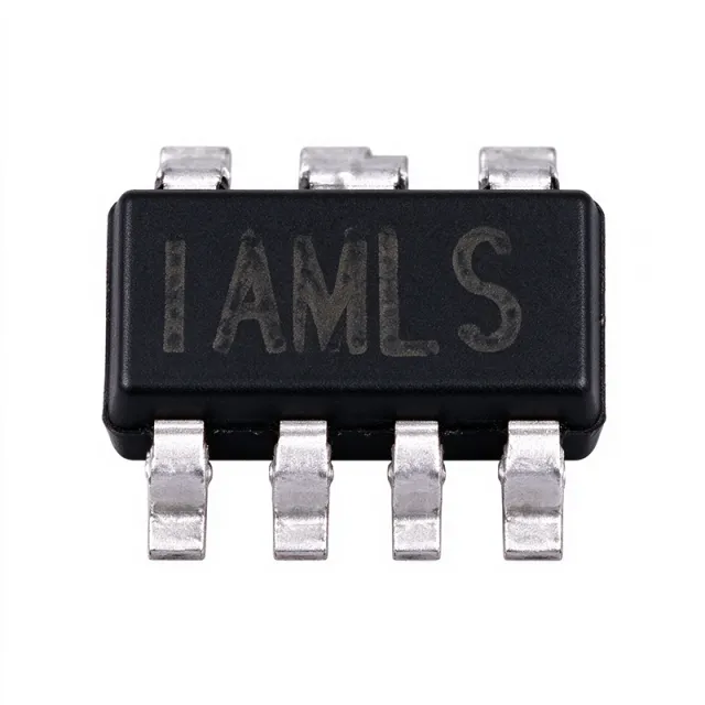
MP2451DJ-LF-Z - 36V, 2MHz, 0.6A Step-Down Converter | MPS
The Monolithic Power Systems MP2451DJ-LF-Z is a high-frequency (2 MHz) step-down switching regulator with an integrated internal high-side high-voltage power MOSFET, delivering up to 0.6 A of output current in a compact TSOT-23-6 (Thin SOT-23-6) package. It operates from a wide 3.3 V to 36 V input range and provides an adjustable output from 0.8 V, using current-mode control for fast transient loop response. A 3 µA shutdown-mode quiescent current makes the device attractive for battery-powered and always-on applications where standby drain matters. A step-down switching regulator (also called a buck converter) is a type of switched-mode power supply (SMPS) that efficiently converts a higher DC input voltage to a lower DC output voltage by rapidly switching an internal MOSFET and storing energy in an external inductor. Within the broader power-management hierarchy, the MP2451 sits between DC-DC converters (the family) and synchronous/non-synchronous buck regulators (the sub-family), making it well-suited for point-of-load (POL) rails in space-constrained designs. The 2 MHz switching frequency lets designers use a tiny 1 µH to 4.7 µH inductor, reducing total solution size dramatically versus 500 kHz alternatives. Key specifications include a 0.6 A continuous output rating, 36 V absolute-maximum input, internal compensation that removes the need for an external compensation network, and built-in protections such as over-current protection (OCP), thermal shutdown, and under-voltage lockout (UVLO). The TSOT-23-6 footprint occupies roughly 2.9 mm × 1.6 mm of board area, making the part one of the smallest 36 V-tolerant synchronous-feel buck regulators on the market. The wide VIN range specifically targets automotive and industrial environments subject to load-dump and cold-crank transients on a 12 V or 24 V bus. Typical applications include distributed 5 V or 3.3 V POL rails from a 12 V/24 V automotive battery, USB-powered devices, IoT sensors, DSL/cable modems, and portable industrial instrumentation. The combination of high switching frequency and small package also suits FPGA/CPLD auxiliary rails where board area is at a premium and low EMI from forced-CCM operation is desired. When laying out the PCB, place the input capacitor, the inductor, and the BST bootstrap component as close to the IC as possible and keep the high-current loop minimal. The exposed ground pad under the TSOT-23-6 must be soldered to a sufficient ground copper pour; the part relies on PCB copper for thermal dissipation, so a thermal via array is strongly recommended when delivering close to the 0.6 A rating continuously.

MP2949 - 3-28V Sync Buck Controller | Monolithic Power Systems
The Monolithic Power Systems MP2949 is a 3V-28V input, hysteretic synchronous step-down controller designed for high-current point-of-load conversion in distributed power architectures. Housed in a compact surface-mount QFN package with exposed thermal pad, the controller drives external high-side and low-side MOSFETs to deliver high efficiency at load currents well above what integrated FET regulators can provide. The wide 3V to 28V input range covers both 5V and 12V intermediate bus rails commonly found in telecom, computing, and industrial systems. A hysteretic control architecture is a type of switching regulator topology that uses output voltage ripple directly to trigger switching events, eliminating the need for an internal error amplifier compensation network. This results in inherently stable operation across a broad range of output LC filter combinations, very fast transient response, and simple external component selection. Hysteretic controllers trade a variable switching frequency for these benefits and are often paired with adaptive ontime variants in modern designs. Key features include programmable valley current limiting for robust overload protection, a wide 0.6V to 5V adjustable output range using an external resistor divider, internal 5V LDO for gate drive supply, and an external soft-start pin for controlled startup into large output capacitors. The exposed-pad QFN package provides a low thermal resistance path, allowing continuous operation at high load currents when properly soldered to PCB ground copper. The hysteretic control eliminates compensation network complexity, simplifying the design-in process. Typical applications include telecom base station point-of-load regulation, FPGA and ASIC core voltage generation, industrial 24V bus intermediate stages, networking switch/router power rails, and high-current DC-DC bricks for server motherboards. The 28V input tolerance also tolerates transient spikes on 24V industrial buses without additional protection circuitry. When designing with the MP2949, place the boot capacitor, bootstrap diode, and high-side MOSFET gate connection on the same PCB layer with minimal loop area to limit switching node ringing. Select the inductor ripple current at 20-40% of full load to balance transient response and conduction losses. Ensure the SNSN and SNSP current-sense traces are routed as a differential pair to reject switching node noise.

MP38876DL-LF-Z - 15A 28V Sync Buck Converter | MPS | QFN-20
The Monolithic Power Systems MP38876DL-LF-Z is a monolithic step-down (buck) switching regulator with built-in internal power MOSFETs, delivering up to 15 A continuous output current from a 4.5 V to 28 V input rail in a 20-pin QFN (3 x 4 mm) package. It integrates a synchronous gate driver for high-side and low-side MOSFETs, enabling high-frequency operation up to 400 kHz and high step-down efficiency across wide load ranges. The output voltage is adjustable down to 0.8 V, with the LF-Z suffix denoting lead-free, tape-and-reel packaging per the MPS datasheet. What is a synchronous buck converter? A buck (step-down) switching converter is a type of DC-DC voltage regulator that efficiently converts a higher input voltage to a lower output voltage by rapidly switching an internal power MOSFET and storing energy in an external inductor. Synchronous buck converters replace the traditional Schottky rectifier with a second MOSFET (synchronous rectifier) to improve efficiency, especially at high output currents. The MP38876 sits within the broader hierarchy: synchronous buck regulator -> step-down DC-DC converter -> switching voltage regulator -> power management IC. Key features include 15 A continuous output current, 4.5 V to 28 V wide operating input range, 0.8 V reference with adjustable output down to 0.6 V, internal soft-start, cycle-by-cycle over-current protection (OCP), and thermal shutdown. The device uses current-mode control that provides fast transient response and eases loop stabilization. A built-in synchronous gate driver eliminates the need for an external bootstrap circuit in many designs. The MP38876DL-LF-Z uses constant-on-time (COT) / current-mode architecture optimized for fast transient response at high step ratios. Its high switching frequency (programmable up to 400 kHz) allows the use of small external LC components, shrinking the total solution footprint. Internal MOSFETs minimize parasitic losses, while the synchronous rectifier architecture achieves high efficiency at 15 A output. This makes the MP38876 particularly well-suited for distributed POL (point-of-load) applications where board space and thermal headroom are constrained. Typical applications include distributed power systems, networking equipment, telecom base stations, industrial controllers, graphic cards, and high-current ASIC/DSP power rails. The wide VIN range also fits 12 V and 24 V industrial bus inputs commonly found in factory automation and telecom hardware. When designing with the MP38876DL-LF-Z, ensure the input capacitor and bootstrap capacitor are placed as close as possible to the IC pins. Choose an inductor with low DCR to limit conduction losses at 15 A, and verify the output capacitors have sufficient ripple current rating. The exposed pad must be soldered to a sufficient copper pour for thermal dissipation. This page synthesizes distributor pricing from Mouser and DigiKey, drop-in same-brand alternatives (MP38876DL-LF-P), and practical design notes not consolidated on the manufacturer datasheet alone.

MP4462DN-LF-Z - 3.5A 36V Step-Down Converter | Monolithic Power Systems
The Monolithic Power Systems MP4462DN-LF-Z is a 3.5 A, 4 MHz, 36 V step-down switching regulator housed in an 8-pin SOIC with exposed thermal pad. It integrates a high-side high-voltage power MOSFET and provides 3.5 A continuous output with current-mode control for fast transient response and easy external compensation, making it suitable for distributed power systems, automotive load-dump environments, and point-of-load conversion. A step-down (buck) converter is a switching DC-DC regulator that efficiently steps a higher input voltage down to a lower regulated output voltage by rapidly switching an internal MOSFET and filtering the resulting pulsed waveform through an external LC network. Within the broader power-management hierarchy, buck regulators belong to the switching-converter family, which sits alongside LDOs, charge pumps, and boost converters. Compared with linear regulators, a buck converter achieves far higher efficiency (typically >90%) because the pass element dissipates little average power, but it does introduce switching ripple and requires inductor/capacitor filtering. Key features of the MP4462DN-LF-Z include a 4.5 V to 36 V wide operating input range (with a 3.8 V minimum undervoltage lockout per the manufacturer datasheet), a fixed 4 MHz switching frequency that enables small inductors and low-EMI footprints, internal soft-start to limit inrush current, and a 120 µA (typ.) quiescent current that suits battery-connected applications. The 8-pin SOIC-8EP package exposes the die thermal pad for direct copper heatsinking, allowing full 3.5 A output at industrial temperatures. The device uses peak current-mode control, providing cycle-by-cycle current limiting and inherent input-voltage feed-forward. The high-side MOSFET is fully integrated, so only an external inductor, Schottky rectifier or low-side synchronous FET, and feedback divider are required to complete a 3.5 A point-of-load supply. According to the Monolithic Power Systems datasheet, efficiency peaks above 92% in typical 12 V-to-5 V and 12 V-to-3.3 V designs. Typical applications include 24 V industrial sensor rails, automotive infotainment and body-electronics supplies, distributed 5 V/3.3 V bus converters from 12 V or 24 V backplanes, and battery-powered equipment requiring wide input-range step-down conversion. The 4 MHz switching frequency permits use of a 1 µH to 4.7 µH inductor, ideal for space-constrained boards. When designing with the MP4462DN-LF-Z, route the feedback trace away from the switching node, place the input ceramic bypass within 2 mm of the IC, and ensure the exposed pad is soldered to a copper area of at least 1 cm² for thermal relief at full 3.5 A current. The output voltage is set from 0.8 V to ~30 V via an external resistor divider; do not exceed the 36 V absolute-maximum input. This page synthesizes distributor pricing, drop-in alternatives, and practical design notes not found in the manufacturer datasheet.

MP8009AGV-Z - 802.3af/at PoE PD Interface & Flyback Controller | MPS
The Monolithic Power Systems MP8009AGV-Z is a fully integrated IEEE 802.3af/at-compliant Power over Ethernet (PoE) powered device (PD) interface with an integrated high-efficiency flyback/forward converter controller, housed in a 28-pin QFN (4x5 mm) package. It combines a complete PD interface and a switching power supply controller in a single IC. A PoE powered device interface is the circuitry at the powered end of an Ethernet link that negotiates and receives power from a PoE switch or injector (the power sourcing equipment, PSE). Within the power management IC hierarchy, the MP8009AGV-Z belongs to the PoE powered device controller family, a subset of Power over Ethernet power interface ICs used in networking and industrial connectivity systems. Key features include full IEEE 802.3af/at functionality covering detection, 1-event and 2-event classification, a 120 mA inrush current limit, an 840 mA operational current limit, and an integrated 100 V rated hot-swap MOSFET that eliminates an external pass device. A 32 ms soft-start time gives controlled converter startup. On the converter side, the flyback/forward controller supports isolated and non-isolated PD power supply topologies, allowing designers to build the downstream DC-DC conversion stage around a single controller IC. Integration of the hot-swap MOSFET, PD interface state machine, and converter controller reduces bill-of-material count and board area compared with discrete PD interface plus separate PWM controller solutions. Typical applications include IP security cameras, wireless access points, VoIP phones, and networked industrial sensors that draw power directly over the Ethernet cable, where the MP8009AGV-Z provides PD detection, classification, inrush limiting, and isolated flyback conversion from the 48 V PoE input rail. Design consideration: verify transformer selection and feedback loop compensation against the MPS MP8009A datasheet design equations, and ensure PCB creepage on the 100 V input side meets the requirements of the target PoE class and isolation specification. This page synthesizes distributor pricing, drop-in alternative analysis, application guidance, and practical design notes not found in the manufacturer datasheet, with data verified against MPS and distributor sources as of 2026-10-19.

MP8759GD-P - 8A, 26V Sync Buck Converter | MPS
The Monolithic Power Systems MP8759GD-P is a fully integrated, high-frequency synchronous step-down (buck) switch-mode converter delivering 8A of continuous output current (10A peak) in a compact 12-pin PowerVFQFN (QFN-12) package. It accepts a wide input supply range and produces an adjustable output from 0.6V (feedback reference) up to 5.5V, with excellent load and line regulation. A synchronous buck converter (also called a step-down or DC-DC switching regulator) is a power management IC that uses integrated high-side and low-side MOSFETs, an oscillator, and a control loop to convert a higher input voltage into a lower regulated output with high efficiency. Within the power-management hierarchy, it sits between raw supply rails (such as 12V or 24V buses) and point-of-load consumers like processors, FPGAs, and memory. Key features include 8A continuous / 10A peak output current, a wide input range suited to 12V and 24V intermediate bus architectures, low quiescent current for light-load efficiency, and a high switching frequency that shrinks external inductor and capacitor sizes. MPS' proprietary control topology keeps efficiency high across a wide output-current load range, which is critical in always-on and multi-rail systems. Technically, the MP8759 integrates the power switches, gate drive, and compensation internally, offering a very compact single-inductor solution. Fixed-frequency switching operation enables predictable EMI filtering, and internal protection features such as cycle-by-cycle current limiting and thermal shutdown guard against fault conditions. Typical applications include FPGA and ASIC core/IO power rails, networking and telecom equipment point-of-load supplies, and industrial 12V/24V bus systems that need a compact high-current step-down stage. When designing with the MP8759GD-P, pay attention to PCB layout: place the input ceramic capacitors and inductor close to the IN and SW pins, and use solid ground planes to minimize the high-frequency switching loop. Verify thermal dissipation at full 8A load with the QFN-12 exposed pad soldered to a copper pour. This page synthesizes distributor pricing, drop-in alternatives, comparison data, and practical design notes not found in the manufacturer datasheet, giving engineers a one-stop selection resource.
MPM3630GQV-Z - 18V/3A Synchronous Buck Module | MPS
The Monolithic Power Systems MPM3630GQV-Z is a synchronous rectified step-down DC/DC power module with built-in power MOSFETs, inductor, and capacitors, delivering up to 3A continuous output current over a 4.5V to 18V input range. The device is housed in a compact QFN-style surface-mount module package with integrated magnetics, achieving 0.6V to 18V adjustable output with excellent load and line regulation. A DC/DC power module (also called a System-in-Package or SiP regulator) integrates the synchronous buck controller, MOSFETs, inductor, and bypass capacitors inside one LGA/QFN module. This converts the part from a discrete component kit into a near drop-in PoL (Point-of-Load) building block, reducing PCB area, BOM count, and design risk compared to a discrete buck design. The module belongs to the broader power management hierarchy: DC/DC converter > synchronous buck regulator > step-down module > integrated PoL regulator. Key features include 1.4MHz switching frequency for fast load transient response, Power Good indicator, internal soft-start, over-current protection, thermal shutdown, and under-voltage lockout. The 1.4MHz high-frequency operation allows the use of small external components while minimizing output ripple. Because the inductor is co-packaged inside the module, radiated EMI and PCB layout sensitivity are reduced compared with a discrete buck design. The MPM3630GQV-Z uses a peak-current-mode control architecture with internal compensation. Synchronous rectification eliminates the Schottky diode of older topologies and improves efficiency at light loads. The wide 4.5V-18V input range makes it compatible with 5V, 9V, 12V, and 15V system rails commonly found in industrial, networking, and FPGA/SoC applications. Typical applications include FPGA/SoC core and I/O rails, industrial control systems, telecom/datacom point-of-load regulation, distributed 12V bus architectures, and consumer electronics requiring compact high-efficiency 3A power. The wide input range simplifies integration into 12V industrial backplanes. When designing with this module, place it directly over the input/output capacitor pads and minimize the loop area of the input capacitors to the module's input pins. Because the inductor is internal, no external inductor selection is required, but adequate airflow or copper heatsinking is still required at high duty-cycle, high-output-current operation. This page synthesizes distributor pricing, verified drop-in alternatives, and practical design notes not found in the manufacturer datasheet.

MPM3682GRE - 18V 10A Step-Down Power Module QFN | MPS
The Monolithic Power Systems MPM3682GRE is a fully integrated 10 A step-down DC/DC power module that combines a synchronous buck converter, power inductor, input/output capacitors, and feedback resistors in a compact 12x12x4 mm QFN package. Operating from 4.5 V to 18 V input (or 2.5 V to 18 V with a 5 V external VCC bias), it delivers an adjustable output from 0.65 V to 5 V with up to 10 A of continuous load current at 500 kHz switching frequency. Background Knowledge: A Point-of-Load (PoL) DC/DC converter is a non-isolated switching regulator placed physically close to the load it powers (typically a processor, ASIC, or FPGA). Within the broader power management hierarchy, a PoL module sits between the intermediate bus converter and the load ICs, providing tight, fast-responding local rails. Fully integrated modules such as the MPM3682GRE differ from discrete buck designs because the high-di/dt power loop (high-side FET, low-side FET, inductor, and input/output bypass capacitance) is contained inside the package, simplifying PCB layout, reducing radiated EMI, and shrinking total solution footprint. Key features include Constant-On-Time (COT) control for fast transient response, simple loop compensation that requires no external RC network, and a solution that needs as few as two external components (one resistor and one capacitor) to operate. Built-in protections include over-current, over-voltage, under-voltage, and over-temperature shutdown. The 12x12x4 mm QFN package exposes a thermal pad that enables direct PCB heat-sinking through the inner power planes. Technical depth: COT control uses the output ripple as part of the PWM ramp, eliminating the need for a closed-loop compensation network in most applications. This architecture achieves sub-microsecond transient response compared with classical voltage-mode or current-mode control, and it scales cleanly to multi-phase or stacked configurations when higher currents are required. Internal MOSFETs and the shielded inductor confine the noisy switching node, keeping the module's radiated EMI signature well below that of a comparable discrete buck. Typical applications include telecom baseband and FPGA core rails, industrial 12 V intermediate-bus POLs, networking switches and routers, server aux rails, and graphics/embedded computing subsystems. The wide 4.5 V-18 V input range covers both 5 V and 12 V intermediate-bus standards, while the 0.65 V-5 V output range supports legacy and modern logic rails from 1.x V cores up to 5 V analog supplies. When designing with this device, place the single feedback resistor and the optional soft-start capacitor immediately adjacent to the FB and SS pins. The exposed pad must be soldered to a continuous ground copper pour with multiple thermal vias to keep junction temperature within ratings at full 10 A load; derate output current linearly above 65 deg C ambient. This page synthesizes distributor pricing, application-ready alternatives, and PCB-level design guidance not bundled in the manufacturer datasheet.
MPM54304GMN-0000 - Quad 3A/3A/2A/2A PMIC Module | MPS
The Monolithic Power Systems MPM54304GMN-0000 is a complete quad-output power management module that integrates four high-efficiency synchronous step-down DC/DC converters, inductors, and a flexible I2C/MTP-programmable logic interface in a single 33-pin PowerFLGA (ultra-thin LGA) package. Operating from a 4V to 16V input, the device delivers configurable output currents of 3A, 3A, 2A, and 2A (with channel 1+2 parallelable to 6A and channel 3+4 parallelable to 4A) across an adjustable output range of 0.55V to 7V, with constant-on-time (COT) control providing ultra-fast load transient response. The module embeds auto-compensation, eliminating the external compensation network that conventional buck converters require. A power management module is a higher-level integration than a discrete DC/DC converter IC: in addition to the controller and FETs, the module embeds the power inductors and most passive components, shrinking the PCB footprint, reducing BOM count, and simplifying layout for multi-rail systems. Within the broader power-management taxonomy, the MPM54304 sits between a point-of-load (POL) regulator and a system PMIC — combining PMIC-style multi-rail programmability with POL-style efficiency and density. The package_svg_key used for the on-page diagram is the 33-pin LGA representation. Key features include I2C digital interface for output-voltage, sequencing, and fault-mask programming; MTP (multi-time programmable) non-volatile memory for storing default configuration; adjustable switching frequency from 500 kHz to 1.6 MHz; power-good indicators per channel; and protection features including OCP, OVP, UVP, and thermal shutdown. According to the MPS datasheet, the COT architecture eliminates the need for loop compensation and enables fast transient response without overshoot. Typical applications include FPGA and SoC core/IO/auxiliary rail generation (the MPS reference design is centered on AMD Zynq-7000), compact industrial control boards, machine-vision cameras, IoT gateways, and any space-constrained multi-rail system where PCB area is at a premium. The 16V maximum input supports 12V bus systems directly. When designing with the MPM54304GMN-0000, follow the MPS EVM54304-MN-01A reference layout for input/output capacitor selection and thermal copper. Place input bulk capacitors within 3 mm of the module. Output voltage setting via I2C overrides the external feedback resistor only after MTP configuration is written. The ultra-thin package requires careful PCB warpage control during reflow.
MPM54304GMN-0001 - 4V-16V Quad-Output PMIC 3A/3A/2A/2A | MPS
The Monolithic Power Systems MPM54304GMN-0001 is a quad-output power module that integrates four high-efficiency synchronous step-down DC/DC converters, integrated inductors, and a flexible I2C/MTP logic interface in a 33-pin PowerFLGA (LGA-33, 7x7x2 mm) package. It accepts an input voltage of 4 V to 16 V and delivers four independently adjustable outputs of 3 A, 3 A, 2 A, and 2 A over an output range of 0.55 V to 7 V at a default 1.5 MHz switching frequency. According to the manufacturer datasheet, the module achieves fast transient response through constant-on-time (COT) control with internal auto-compensation, eliminating the need for an external compensation network. A Power Management IC (PMIC) is a highly integrated voltage regulator that consolidates multiple DC/DC and LDO rails into a single package to power processors, FPGAs, and SoCs. In the system hierarchy, a PMIC sits below a discrete buck converter and above a simple LDO, occupying the role of complete subsystem power management; the MPM54304 specifically belongs to the quad-output, high-current, point-of-load PMIC subcategory. The MPM54304GMN-0001's output voltage can be set via I2C or by an external resistor divider, and the MTP (multi-time programmable) memory allows factory customization of default voltages, sequence, and timing for each rail. Key features include four synchronous step-down converters in a single ultra-thin 2 mm module, internal compensation, constant-on-time control with fast load-step response, I2C-configurable output voltages and fault thresholds, MTP-programmable defaults, integrated soft start, and full protection (OCP, OVP, UVP, OTP). The switching frequency is factory-set to 1.5 MHz by default, allowing the use of small ceramic input and output capacitors and minimizing PCB area compared with discrete buck solutions that require external inductors and compensation components. Typical applications include FPGA/SoC power for AMD Zynq-7000 family and similar MPSoCs, multi-rail industrial automation boards, compact networking switches, point-of-load regulation for PCIe cards, and any dense PCB that previously required four discrete buck converters with inductors. The module replaces at least eight to twelve discrete components per board, reducing BOM count, layout complexity, and EMI risk from separate inductor loops. When designing with this device, ensure that the 4 V to 16 V input range is respected, route the AGND/DGND return as a single-star ground, and place the bootstrap capacitors as close as possible to the BST pins. For non-I2C designs, the SCL/SDA pins must be terminated per the manufacturer's forum guidance (typically pulled up or grounded as documented), and the output resistor divider must use 1% resistors for set-point accuracy.
MPQ2167BGDE-AEC1-P - 6V, 4A Sync Buck Converter, AEC-Q100 | MPS
The Monolithic Power Systems MPQ2167BGDE-AEC1-P is a frequency-programmable, AEC-Q100-qualified synchronous step-down (buck) converter that delivers up to 4 A of continuous output current from a 2.7 V to 6.0 V input rail, packaged in an 11-pin PowerVQFN module with wettable flanks. The output voltage is adjustable down to 0.606 V using an external resistor divider, and the switching frequency is configurable from 300 kHz to 2.2 MHz through an external resistor, allowing the designer to trade efficiency against solution size. Peak-current-mode control provides excellent transient response and simplifies loop compensation across the wide switching-frequency range. A buck converter (also called a step-down switching regulator) is a switch-mode DC-DC converter topology that uses an internal high-side MOSFET, an external or integrated low-side MOSFET, an inductor, and output capacitors to efficiently reduce a higher DC input voltage to a lower regulated output voltage. Within the broader product hierarchy, this part belongs to the synchronous-buck family of voltage regulators, which sits inside the DC-DC switching regulator category, inside the power management IC family, inside the semiconductor category. Synchronous designs replace the traditional Schottky rectifier with a low-side MOSFET, raising light-load efficiency and reducing conduction losses - critical in 3.3 V and 5 V point-of-load applications. Key features of the MPQ2167BGDE-AEC1-P include 4 A continuous output current, 2.7 V to 6.0 V input range, 0.606 V minimum output, 300 kHz to 2.2 MHz programmable switching frequency, internal power MOSFETs, AEC-Q100 Grade 1 qualification for automotive environments, and a wettable-flank PowerVQFN package that supports automated optical inspection of solder joints. The wide frequency range and small solution footprint suit space-constrained automotive infotainment, ADAS sensor rails, and industrial point-of-load designs. Typical applications include automotive infotainment and cluster power rails, ADAS camera/sensor power, industrial PLC and factory-automation logic rails, USB-PD and 5 V point-of-load regulation, FPGA/SoC core and I/O supplies, and portable battery-powered equipment. The AEC-Q100 qualification makes it particularly attractive for under-the-hood and body-electronic modules subject to wide temperature swings. When designing with this device, place the input ceramic capacitors immediately adjacent to the VIN and PGND pins to minimize switching-node ringing, and choose the inductor such that peak-to-peak ripple current stays around 30% of the load. Estimate: at 4 A load, 600 kHz fsw, and 3.3 V VOUT, a 1.5 uH inductor gives roughly 0.45 A ripple. A 2-layer PCB with a continuous ground plane is recommended for thermal dissipation. This page synthesizes distributor pricing, drop-in alternatives, and practical design notes not found in the manufacturer datasheet alone.

MPQ2908AGF-AEC1 - 60V Sync Step-Down Controller, AEC-Q100 | MPS
The Monolithic Power Systems MPQ2908AGF-AEC1 is an AEC-Q100 qualified, 4V to 60V input, current-mode synchronous step-down switching controller housed in a 20-pin TSSOP-20EP (Exposed Pad) package. It directly steps down high-voltage rails such as automotive 12V/24V buses and industrial 48V systems to logic-level outputs with high efficiency. The controller drives dual N-channel MOSFETs in a synchronous buck topology with accurate cycle-by-cycle current limiting. A synchronous step-down controller (buck controller) is a type of DC-DC switching regulator that uses an external pair of MOSFET switches and an LC output filter to convert a higher input voltage to a lower regulated output voltage. It sits in the power management IC family, between discrete switching regulators and fully integrated synchronous buck ICs, and is preferred when output current exceeds the capability of monolithic converters. The MPQ2908A family targets wide-Vin, high-current automotive and industrial rails where a controller plus external MOSFETs gives designers flexibility on current, RDS(on), and thermal budget. Key features include a wide 4V to 60V operating input range, current-mode PWM control with cycle-by-cycle over-current protection, an Advanced Asynchronous Mode (AAM) for improved light-load efficiency, and AEC-Q100 Grade qualification for automotive environments. The TSSOP-20EP exposed pad offers a low thermal resistance path to PCB copper for dissipating controller-side losses. Built-in protection features include OCP, OVP, UVLO, and thermal shutdown. The architecture uses peak current-mode control with internal slope compensation, providing excellent line-transient response and simple single-loop compensation. The MPQ2908AGF-AEC1 supports both continuous-conduction synchronous operation at heavy loads and diode-emulation AAM at light loads to reduce switching losses. An external SS/TRK pin sets soft-start and tracking behavior for sequencing in multi-rail systems. Typical applications include automotive infotainment and ADAS power rails, 24V industrial sensor and PLC supplies, battery-powered e-mobility systems (48V e-bike, forklift, light EV), telecom 48V backplane POL conversion, and point-of-load regulators in distributed 24V industrial racks. The wide Vin and AEC-Q100 grade make it a strong fit for any 12V/24V/48V bus system. When designing with this controller, select external MOSFETs rated for the application's maximum load current and Vin transients (load-dump tolerant up to 60V), and choose the inductor such that ripple current is roughly 30% of full load. Place the input/bootstrap capacitors close to the SW and BST pins to minimize switching-node parasitic inductance and ringing. For automotive designs, follow MPS's EMI mitigation layout note for two-layer boards.
MPQ3431AGL-AEC1-Z - 21A Synchronous Boost Converter | MPS | AEC-Q100
The Monolithic Power Systems MPQ3431AGL-AEC1-Z is a 21 A high-efficiency fully-integrated synchronous boost converter with configurable input current limit, housed in a 13-pin PowerVFQFN (QFN-13 3x4 mm) package and AEC-Q100 qualified for automotive applications. A boost converter (also called a step-up converter) is a switching DC-DC power topology that produces an output voltage higher than its input voltage by storing energy in an inductor during the switch-on phase and releasing it into the load during the switch-off phase. Synchronous boost converters replace the conventional Schottky rectifier with a low-side MOSFET, which dramatically reduces conduction losses and improves efficiency at high output currents. The MPQ3431A occupies the power management IC (PMIC) tier within the DC-DC switching regulator family, which itself sits under the broader power management umbrella for battery-powered and automotive electrical systems. Key headline specifications include a 21 A switch current capability, a fixed 450 kHz switching frequency, a wide 2.7 V to 13 V start-up input range, an adjustable output voltage from 0.8 V upward, and a selectable MODE pin that allows the user to choose pulse-skip mode (PSM), forced continuous conduction mode (FCCM), or ultrasonic mode (USM) under light-load conditions. The integrated low-side MOSFET also handles cycle-by-cycle inductor peak current limiting, eliminating the need for an external sense resistor. The device adopts constant-off-time (COT) control topology, which provides fast transient response to load steps - a critical advantage over traditional voltage-mode or current-mode PWM controllers in automotive load-dump and cold-crank scenarios. The configurable input current limit provides accurate overload protection from a misbehaving upstream supply, while the high-side and low-side MOSFET integration simplifies PCB layout and reduces bill-of-materials cost. The 3 mm x 4 mm PowerVQFN package with an exposed thermal pad supports continuous high-current operation with proper PCB thermal design. Typical applications include automotive front-camera power, infotainment USB-PD rails, eCall backup supplies, ADAS sensor biasing, and 12 V battery-to-boosted rails for audio amplifiers. The AEC-Q100 Grade 1 qualification makes the part especially suitable for under-hood and safety-relevant automotive subsystems. Designers should pay particular attention to inductor selection - the constant-off-time topology with a 450 kHz nominal frequency pair well with 1-3 µH power inductors rated for at least 25 A saturation current. The MODE pin must be tied high, low, or left floating according to the desired light-load behavior. This page synthesizes distributor pricing, parametric drop-in alternatives, and practical design notes that go beyond the manufacturer datasheet to accelerate automotive power design.

MPQ4420-AEC1 - 2A 36V Sync Buck Converter | MPS | Automotive
The Monolithic Power Systems MPQ4420-AEC1 is an automotive-grade, high-efficiency synchronous step-down (buck) switch-mode converter with built-in power MOSFETs, delivering up to 2A of continuous output current from a wide input supply range up to 36V maximum, packaged in a space-saving 8-pin TSOT23-8 (SOT-23-8 Thin, TSOT-23-8) surface-mount package with power-good (PG) indication and external synchronization support. A synchronous buck converter is a type of DC-DC switching regulator that uses two internal MOSFETs - a high-side switch and a low-side synchronous rectifier - instead of a Schottky diode, reducing conduction losses and raising efficiency across the load range. Within the power-management hierarchy, the MPQ4420-AEC1 sits in the step-down converter family of switching regulators, part of a broader power supply IC chain that converts a higher unregulated input voltage into a tightly regulated lower output voltage. Key differentiating features include a 2A continuous output current rating with excellent load and line regulation over a wide input supply range, an output voltage adjustable down from 0.8V (the feedback reference), current-mode control, and AEC-Q100 Grade 1 automotive qualification. Protection features include cycle-by-cycle over-current protection with hiccup-mode restart, and thermal shutdown. Architecturally, the MPQ4420 uses current-mode operation, which provides fast transient response and eases loop stabilization compared with voltage-mode control. Synchronous rectification maintains high efficiency from light load to full 2A load. When the inductor current peak exceeds the set current limit and the feedback voltage falls below the under-voltage threshold (typically 84% below the reference), the part enters hiccup mode and periodically restarts, protecting the converter during short-circuit faults. Typical applications include automotive power systems (the -AEC1 suffix denotes AEC-Q100 qualified automotive grade), industrial auxiliary power rails from 12V/24V buses, and distributed point-of-load regulation where a compact, minimal-external-component buck solution is required. A key design consideration is thermal and layout discipline: with an integrated MOSFET buck in a TSOT23-8 package, keep the input ceramic capacitor and inductor loops tight and provide adequate copper area on SW and GND for heat dissipation at high input-to-output voltage ratios. This page synthesizes verified datasheet data, drop-in family alternatives, comparison tables, and practical design notes not found together on distributor listing pages.
MPQ4420GJ-Z - 2A 36V Sync Buck Converter | Monolithic Power Systems
The Monolithic Power Systems MPQ4420GJ-Z is a high-frequency, synchronous, rectified step-down switch-mode converter with built-in power MOSFETs, delivering 2 A continuous output current from a 4 V to 30 V input, with an adjustable output of 0.8 V to 27 V in an 8-pin TSOT23 (SOT-23-8 Thin) package. It operates at a 410 kHz switching frequency and is AEC-Q100 qualified for automotive use. A synchronous step-down (buck) converter is a type of DC-DC switching regulator that uses internal high-side and low-side MOSFETs instead of an external Schottky diode to step a higher input voltage down to a lower output voltage. Within the power management hierarchy, the buck converter sits under switching regulators, which themselves belong to the broader family of voltage regulators and power management ICs. Synchronous rectification improves efficiency, especially at light-to-medium loads. Key features include integrated power MOSFETs that minimize external component count, synchronous mode operation for higher efficiency across the full load range, current-mode control for fast transient response and easy loop stabilization, and a compact 8-pin TSOT23 footprint. Full protection features include over-current protection and thermal shutdown. Technically, the MPQ4420 uses current-mode architecture, which simplifies compensation and gives excellent load and line regulation over the wide 4 V to 30 V input supply range. The internal MOSFETs and 410 kHz switching frequency allow small inductors and capacitors, enabling very compact power solutions. The adjustable feedback pin supports output voltages from 0.8 V up to 27 V. Typical applications include automotive infotainment and auxiliary power rails, industrial 24 V bus point-of-load conversion, and distributed power systems in networking and telecom equipment where a wide input range and 2 A output are required. Design consideration: at 410 kHz, keep the SW node loop area small and place the input ceramic capacitor close to the IN and GND pins; verify thermal performance when running 2 A at high input-to-output differential. This page synthesizes distributor pricing context, drop-in alternatives, cross-reference data, and practical design notes not found in the manufacturer datasheet.
NBM2317S60D1580T0R - 800W Non-Isolated Bus Converter 48V-to-12V | Vicor
The Vicor NBM2317S60D1580T0R is a high-efficiency non-isolated, fixed-ratio bidirectional bus converter operating from a 40 to 60 VDC high-side voltage bus to deliver a ratiometric low-side voltage from 10 to 15 VDC, with a continuous output power rating of 800 W and 97.9% peak efficiency. A bus converter (BCM, bus converter module) is a specialized DC-DC converter that uses a fixed turn ratio (rather than closed-loop PWM duty-cycle regulation) to step a high-voltage distribution bus down to a lower intermediate voltage, then feeds downstream point-of-load regulators. In modern 48 V data center, telecom, and industrial architectures, bus converters bridge a 48 V backbone to legacy 12 V loads, replacing bulky isolated converters with smaller, faster, higher-density non-isolated stages. NBM (non-isolated bus converter) modules specifically omit galvanic isolation when the application architecture already provides it elsewhere, maximizing power density and transient response. Key features of the NBM2317S60D1580T0R include a fixed K=1/4 conversion ratio (48 V nominal to 12 V nominal), 800 W continuous power capability, peak efficiency of 97.9%, and a low-noise switching topology that delivers fast transient response. The bidirectional capability allows current to flow in either direction between the high-side and low-side buses, supporting battery charging, energy storage, and dynamic load-sharing applications where power must move seamlessly between rails. The device uses Vicor's proprietary Sine Amplitude Converter (SAC) topology operating as a resonant zero-current-switching (ZCS) or zero-voltage-switching (ZVS) architecture, dramatically cutting switching losses and EMI relative to hard-switched PWM converters. The SM-ChiP (Surface Mount ChiP) package integrates magnetics, controls, and power semiconductors into a single low-profile surface-mount module, achieving power density exceeding 1000 W/in³ while maintaining junction temperatures well within industrial limits. Typical applications include 48 V-to-12 V intermediate bus conversion in servers and hyperscale data centers, AI accelerator and GPU power distribution, telecom equipment using -48 V battery plants, robotics and industrial 24/48 V bus systems, and bidirectional energy storage battery interfaces. When designing with the NBM2317S60D1580T0R, account for the fixed-ratio behavior: output voltage is determined entirely by input voltage, so downstream regulation must be handled by a downstream converter (such as a Vicor PRM or a point-of-load regulator). Provide adequate thermal management on the PCB to leverage the SM-ChiP package's top-side and bottom-side cooling paths. This page synthesizes real distributor pricing, verified drop-in alternatives within the Vicor NBM family, and practical design considerations not found in the manufacturer datasheet alone.
NBM2317S60D1580TMR - 1080W Non-Isolated Bus Converter | Vicor
The Vicor NBM2317S60D1580TMR is a high-efficiency non-isolated bus converter module designed to bridge 48V and 12V power-system domains. It operates from a 40V to 60V high-side input and delivers a ratiometric low-side output of 10V to 15V at up to 80A (1080W peak), with 97.9% peak efficiency. The SMD variant uses Vicor's 2317 Chameleon package with surface-mount termination for high-density PCB assembly. What is a non-isolated bus converter? A non-isolated bus converter (NIBC) is a fixed-ratio DC-DC converter used as a virtual supply rail in distributed power architectures. Unlike a switching regulator, an NIBC divides an existing high-voltage bus into a lower-voltage sub-rail using a capacitive energy-transfer topology. NIBC sits in the power-converter hierarchy as a category between point-of-load regulators and isolated DC-DC converters, providing high step-down ratios without transformer isolation. Key features of the NBM2317S60D1580TMR include a continuous 800W power rating, fixed 4:1 conversion ratio, 1.4 MHz switching frequency, parallelable operation for higher power, and bi-directional power flow capability. Typical conversion efficiency reaches 97.9% at nominal 48V/12V operation, reducing thermal losses compared to traditional buck converters at the same current rating. The NBM family from Vicor uses a proprietary Sinusoidal Amplitude Converter (SAC) topology combined with a zero-voltage, zero-current switching (ZVZCS) soft-switching architecture. This topology achieves high efficiency by eliminating switching losses and uses small ceramic bypass capacitors instead of bulky inductors or transformers. The result is a low-profile surface-mount module that fits between a 48V intermediate bus and downstream 12V point-of-load converters or direct loads. Typical applications include 12V intermediate bus generation in 48V telecom and data-center servers, AI accelerator and GPU auxiliary rails, high-current 12V distribution in industrial equipment, battery energy storage systems using 48V architecture, and bridging converters for automotive 48V mild-hybrid systems. When designing with this part, account for the fixed 4:1 conversion ratio: VOUT follows VIN/4 with a tolerance band. Use the module in conjunction with downstream buck or ZVS regulators for sub-ratios (5V, 3.3V, 1V). Provide adequate PCB copper beneath the surface-mount land pattern for thermal dissipation and high-current return paths. This page synthesizes distributor pricing, drop-in module equivalents, and paralleling notes not found in the manufacturer datasheet.
NBM2317S60E1560T0R - 800W Non-Isolated Bus Converter 60A | Vicor
The Vicor NBM2317S60E1560T0R is a 800 W Non-Isolated Bus Converter Module operating from a 38 V to 60 VDC high-side bus to deliver a ratiometric low-side voltage of 9.5 V to 15 VDC at up to 60 A continuous current, housed in a surface-mount ChiP (Chip-in-Plastic) package. It achieves 97.9% peak efficiency, up to 4.5 kW/in³ power density, and provides bidirectional start-up and steady-state operation with up to 1 kW, 2 ms peak power capability. A bus converter (also called a Bus Converter Module, BCM or NBM in Vicor nomenclature) is a fixed-ratio, non-isolated DC-DC converter that steps a higher distribution voltage down by a deterministic factor (in this case K=1/4 approx, 38-60V -> 9.5-15V) to power downstream point-of-load (PoL) regulators. Unlike a discrete buck regulator, the bus converter uses a Sine Amplitude Converter (SAC) topology with a proprietary zero-voltage-switching (ZVS) / zero-current-switching (ZCS) architecture, achieving high density and low noise. In a system hierarchy it sits above PoL regulators (DCM, PRM, PoL converters) and is part of the Factorized Power Architecture (FPA) ecosystem from Vicor. Key features include 60 A rated output current (step-down operation), 38-60 V high-side input range, a 9.5-15 V ratiometric low-side output, and 97.9% peak efficiency. The module provides low output impedance well beyond the bandwidth of most downstream PoL regulators, meaning input capacitance that would normally sit at the PoL input can be moved to the high-voltage side, reducing PCB area and BOM count. Technically, the NBM2317S60E1560T0R uses Vicor's proprietary SAC topology with a high-frequency soft-switching architecture achieving >97% efficiency at typical loads. The part is bidirectional, capable of start-up and steady-state operation in either direction when used with Vicor's PRM or BCM companion parts. Two cooling configurations are supported: two-sided cooling and bottom-side only (through-PCB) cooling, with thermal models provided for each. Typical applications include 48 V data center and telecom intermediate bus conversion, distributed power architectures for AI accelerators and GPUs, high-end computing motherboards, industrial 48 V robotics, and aerospace distributed power systems. The bidirectional capability makes it suitable for energy storage and battery systems as well. When designing with this device, ensure adequate PCB copper thermal mass or attach to a cold plate. Use Vicor's companion evaluation boards for thermal characterization and consult the datasheet for derating curves beyond the 60 A continuous rating. This page synthesizes distributor pricing, drop-in same-family alternatives, comparison data, and practical design guidance not assembled on any single manufacturer or distributor page.
NBM2317S60E1560T0R-VICOR - 800W Non-Isolated Bus Converter | Vicor
The Vicor NBM2317S60E1560T0R is a non-isolated, fixed-ratio DC-DC bus converter module (BCM) using Vicor's proprietary Sine Amplitude Converter (SAC) topology, delivering up to 800 W of continuous output power from a 38 V to 60 V input range to a ratiometric 13.5 V output at 60 A, in a surface-mount Chip (ChiP) package. It achieves a peak efficiency of 97.9 percent at moderate loading and supports bidirectional start-up and steady-state operation, enabling battery-source and bus-source flexibility. A bus converter module (BCM) is a fixed-ratio, non-isolated DC-DC converter that divides an intermediate bus voltage by a fixed K-factor (turns ratio equivalent) to produce a lower, regulated-feeling output. BCMs sit between an isolated front-end converter and downstream point-of-load (PoL) regulators, providing a low-impedance intermediate voltage rail with fast transient response and high efficiency. As fixed-ratio devices, BCMs cannot regulate output voltage independently of input voltage - regulation is achieved by the upstream front-end converter and downstream PoL stages, while the BCM provides the power transformation with minimal loss. Key features include a fixed K-factor of 1/4, a sinusoidal SAC switching waveform that minimises EMI and acoustic noise, low AC impedance beyond the bandwidth of typical PoL regulators, and up to 4.5 kW per cubic inch power density. The device supports up to 1 kW peak output for 2 ms transient events, an integrated thermal management footprint accepting either two-sided or bottom-side PCB cooling, and parallel operation capability for higher power rails. The ChiP surface-mount form factor eliminates through-hole magnetics and shrinks the converter footprint by an order of magnitude compared with discrete bus-converter designs. The NBM2317S60E1560T0R uses a zero-voltage switching (ZVS), zero-current switching (ZCS) Sine Amplitude Converter architecture operating at a fixed fundamental frequency in the megahertz range. The fixed K-factor of 1/4 means any input from 38 V to 60 V produces an output of 9.5 V to 15 V (Vin/4); the stated nominal output is 13.5 V at the typical 54 V nominal input. The bidirectional capability allows the same module to operate as a step-down or step-up converter, supporting battery charging and energy-storage applications without a second power path. Typical applications include 48 V telecommunications intermediate bus architectures, blade-server and high-performance compute power delivery, battery-backed 48 V infrastructure, industrial automation systems with 48 V or 54 V distribution, and high-current PoL rails where upstream isolation is handled separately. Designers commonly cascade this BCM with downstream PRM (pre-regulation) and VTM (voltage transformation) Vicor components, or with a family of point-of-load regulators from the same Vicor ecosystem. When designing with this device, ensure that input voltage remains within the 38 V to 60 V window under all line and load transients, and that the upstream source can absorb reflected ripple current from the BCM. The ChiP solder-pad layout is not compatible with hand-soldered or socketed assemblies - it requires a reflow profile aligned with the J-STD-020 MSL rating for the part. This page synthesises distributor pricing, drop-in same-family alternatives, and practical thermal-layout notes that are not gathered in any single manufacturer datasheet, giving engineers a faster path to a verified BOM decision.

NCL2801CDADR2G - High-Efficiency CrM Boost PFC Controller
The onsemi NCL2801CDADR2G is a high-efficiency current-mode critical-conduction-mode boost power-factor correction controller packaged in an 8-pin SOIC. It is designed for LED-lighting power supplies and other AC-DC boost PFC stages handling substantial bulk-capacitor ripple. Its headline features are current-mode CrM control, enhanced line-current total harmonic distortion performance, Valley Count Frequency Fold-back operation, and a 12.5 V start voltage. A power-factor controller is an integrated circuit that shapes input current drawn from an AC mains line so that current tracks voltage and the upstream system approaches unity power factor. In the broader hierarchy, the NCL2801 belongs to AC-DC power conversion, power management integrated circuits, and boost PFC controllers. Correct operation reduces reactive current, line-current distortion, and stress in upstream magnetic and capacitor components. The NCL2801 uses THD Enhancer technology to improve line-current total harmonic distortion across an extended operating range. It operates classically in Critical Conduction Mode at high loads. When load decreases, Valley Count Frequency Fold-back forces discontinuous conduction by introducing dead time corresponding to a fixed number of valleys, improving standby behavior while maintaining regulation. The 8-SOIC package supports compact offline-lighting designs. The controller is intended to drive PFC boost stages rather than directly switching the mains-connected power stage. A typical implementation combines the NCL2801 with a boost inductor, switching MOSFET, current-sense resistor, bridge rectifier, bulk capacitor, safety-rated components, and LED-driver downstream circuitry. The controller supplies control and protection functions, while the external power components determine available output power and conversion ratio. Typical applications include LED lamps and luminaires, electronic ballasts, compact offline LED power supplies, and cost-effective high-efficiency AC-DC front ends. The device is especially useful where low line-current THD, low standby power, and tolerance of high ripple on the bulk capacitor are important. Its lighting-focused feature set helps designers meet EMI and input-current-shape requirements without relying on a more complex digital controller. Design the feedback network and compensation for the actual boost converter, not as a generic voltage-regulator stage. Keep the current-sense loop short, isolate high-voltage switching nodes from sensitive control traces, and follow the manufacturer's application guidance for layout and component values. Review the datasheet limits before selecting the MOSFET, inductor, capacitor, and safety components. This page combines the verified manufacturer description, package and distributor information, application guidance, and engineering-oriented replacement limitations. It does not infer unprovided electrical limits or claim a pin-compatible replacement when the available cross-reference results do not establish one.

NCP1294 - Fixed Frequency PWM Controller for Flyback/Forward/Boost | onsemi
The onsemi NCP1294 is a fixed frequency, feed forward voltage mode PWM controller optimized for high frequency primary side control in Flyback, Forward, or Boost converter topologies. It integrates a complete set of control features including soft start, accurate duty cycle limit, less than 50 uA startup current, and dedicated over and under voltage protection. The device operates from a VCC supply commonly fed via an auxiliary winding, and it drives an external MOSFET through a totem pole output stage sized for direct gate drive in low to medium power converters. A PWM controller is a building block inside switched mode power supplies (SMPS) that produces a fixed frequency clock and modulates its duty cycle to regulate the converter output voltage. In the hierarchy of power management ICs, the NCP1294 sits as a current mode/peak control sub-family member: PWM controller -> SMPS controller -> DC-DC controller -> power management IC -> semiconductor. Its feed forward voltage mode architecture adds line-voltage feed forward to reject input voltage transients faster than a conventional voltage mode controller can respond through its error amplifier loop alone. Key features include programmable maximum duty cycle clamp, cycle-by-cycle current limit, internal soft start, undervoltage lockout, overvoltage protection, and a low startup current below 50 uA which simplifies self bias designs from the input bulk rail. The controller typically operates at switching frequencies programmable up to the audio band and beyond, enabling smaller magnetics in isolated telecom and industrial auxiliary supplies. The architecture uses a leading edge blanking interval to mask the leading edge current spike caused by the MOSFET turn on transient, improving noise immunity at the current sense input. Internally the oscillator is trimmed and the reference is bandgap based for stable operation over temperature, supporting industrial operating ranges typical of -40C to +125C. The combined UVLO and OVP set the input supply window for the IC itself, simplifying the housekeeping design on the primary side. Typical applications for the NCP1294 include isolated telecom auxiliary supplies such as 48 V to low voltage DC-DC bricks, industrial DIN rail and process control power modules, AC-DC adapters up to several hundred watts using forward or flyback topologies, and standby/auxiliary rails in server and PoE powered systems. Its configuration flexibility also suits it for boost derived front end PFC auxiliary rails and small solar micro inverter auxiliary supplies. When designing with the NCP1294, pay close attention to current sense resistor placement and to the CS pin filter network, because the leading edge blanking only masks the first few hundred nanoseconds of the turn on spike; longer ringing from a poor layout will inject false current limit triggers. Use a small RC on the CS pin and keep the sense loop area minimal. This page consolidates onsemi datasheet parameters, distributor stock pricing, and same-package drop-in alternatives such as the NCP1294C and NCP1284 into a single engineering reference so that sourcing, replacement, and design decisions can be made without cross referencing multiple distributor and manufacturer PDFs.
NCP1294DB - Fixed-Frequency PWM Controller | onsemi
The onsemi NCP1294DB is a fixed-frequency, feed-forward, voltage-mode PWM controller optimized for high-frequency primary-side control. It supports basic flyback, boost, and forward-converter topologies, operates from the DC input rail supplying the primary circuit, and is packaged for surface-mount assembly. The verified manufacturer material specifically identifies soft-start, accurate duty-cycle limiting, less than 50 uA startup current, overvoltage and undervoltage protection, and current-mode operation as key features. A PWM controller is a semiconductor timing and regulation device used in switched-mode power supplies. Its oscillator establishes the switching frequency, while its control loop compares a feedback signal with an internal reference and adjusts the gate-drive command. The NCP1294DB belongs to the DC-DC power-conversion controller category and is intended for isolated flyback or forward designs as well as non-isolated boost arrangements. Feed-forward voltage-mode control is especially relevant to offline power-conversion systems where predictable duty-cycle behavior and primary-side regulation are important. The controller’s fixed-frequency architecture simplifies compensation planning because the nominal switching point does not vary with input voltage. Soft-start helps limit inrush stress during power-up, while accurate duty-cycle limiting constrains the maximum commanded on-time. The low startup current is intended to reduce the burden on the startup path before the auxiliary supply becomes operational. Overvoltage and undervoltage protection provide additional system safeguards, although exact thresholds, tolerances, response timing, and restart behavior must be taken directly from the manufacturer datasheet. The NCP1294 is designed for high-frequency primary-side control, making it relevant to compact AC/DC adapters, offline power supplies, forward converters, boost converters, and industrial control systems. In an isolated flyback design, the controller drives a primary MOSFET while an optocoupler or other isolation mechanism communicates output-voltage information. In a forward converter, transformer reset and duty-cycle constraints determine the practical power level. In a boost design, the same controller family supports a non-isolated conversion stage when its voltage and timing limits are satisfied. Designers should use the datasheet’s recommended oscillator, compensation, current-sense, startup, and gate-drive networks rather than treating generic PWM-controller layouts as directly interchangeable. Transformer reset time, propagation delay, MOSFET switching speed, output-capacitor ESR, feedback bandwidth, and safety spacing all affect practical performance. NCP1294DB is a controller, not a complete power stage; an external MOSFET, magnetics, rectifier, feedback network, and protection components remain necessary. This page summarizes the verified NCP1294DB architecture, application fit, and design considerations while distinguishing documented features from parameters that were not supplied in the retrieved source text. For sourcing, confirmation of current lifecycle and exact package-related ordering details should be completed before committing a production design.