Leistungsmanagement
Unterkategorien
Produkte (2770)

UC3770AN - 2A Bipolar Stepper Motor Half-Bridge Driver | TI
The Texas Instruments UC3770AN is a high-performance, bipolar stepper motor full-bridge driver IC delivering up to 2 A of bipolar output current, housed in a 16-pin PDIP (N) through-hole package. The device supports full-step, half-step, and micro-step operation from a wide motor supply of 10 V to 50 V, while internal logic is powered from a separate 4.75 V to 5.3 V rail. Two UC3770AN ICs paired with a few external components build a complete µP-controllable bipolar stepper drive. A stepper motor driver (also called a stepper controller or bipolar H-bridge driver) belongs to the broader class of motor / motion / ignition controllers, which sit inside the power-management and signal-conditioning hierarchy of industrial automation. These ICs convert TTL-level step and direction logic into precisely chopped bipolar phase currents that move a permanent-magnet or hybrid stepper motor by a fixed electrical angle per step, enabling open-loop positioning without an encoder. Key features of the UC3770AN include integrated LS-TTL compatible logic inputs, on-chip current sense, a monostable timing stage, thermal shutdown protection, and a power H-bridge output stage with low saturation voltage. The integrated current-sense comparator and external sense resistor let designers program the per-phase chopping current, while the monostable sets the fixed off-time for constant-off PWM current control. Architecturally the UC3770AN combines bipolar analog control blocks (bandgap reference, comparators, monostable) with DMOS-style output H-bridge transistors, giving lower saturation voltage than earlier bipolar-only TI parts such as the UC3717 and the original UC3770. This translates into cooler operation at 2 A phase current and higher torque-per-watt efficiency. Typical applications include industrial stepper drives for CNC routers, 3D printers, pick-and-place heads, textile and packaging machinery, and laboratory automation. The device is well suited to bipolar two-phase or four-phase stepper motors rated from a few hundred mA up to 2 A phase current at 24 V or 48 V rails. When designing with this part, place the sense resistors close to the sense pins to minimize ground-bounce errors, and provide a bulk decoupling capacitor of at least 100 µF on the motor supply to absorb PWM switching current. Decouple the logic supply with a 0.1 µF ceramic near the VCC pin to keep TTL-level noise off the timing-critical monostable. This page combines real distributor pricing, true drop-in alternatives, and field-tested design notes not found in the UC3770A family datasheet, giving engineers a single reference for sourcing, replacement, and PCB layout decisions.

UC3824 - 1.5A High Speed PWM Controller | Texas Instruments
The Texas Instruments UC3824 is a high-speed, double-ended PWM controller designed for switch-mode power supplies requiring operating frequencies up to 1 MHz. It integrates a 30-V, 1.5-A totem-pole output stage capable of driving power MOSFETs directly, along with a 9.2-V/8.4-V undervoltage lockout (UVLO) and a maximum duty cycle of 85%. The device is available in a 16-pin PDIP package (UC3824N) and operates over the commercial temperature range of 0°C to 70°C. A PWM controller is an integrated circuit that generates the pulse-width-modulated signals used to control the switching elements in a DC-DC converter or power supply. It forms the core of the control loop, regulating output voltage or current by varying the duty cycle of the switching waveform. The UC3824 belongs to the family of current-mode PWM controllers, which offer superior line regulation and simpler compensation compared to voltage-mode controllers. In the hierarchy of power management, it sits between the power stage (MOSFETs, transformers) and the supervisory circuitry, providing the precise timing and drive signals essential for efficient power conversion. Key features of the UC3824 include a 50-ns propagation delay to output, enabling high-frequency operation with minimal phase lag. The dual totem-pole outputs can source and sink 1.5 A, providing robust gate drive for large MOSFETs. The device also includes a current-limit comparator with a 1-V threshold, a TTL-compatible shutdown port, and a soft-start pin that doubles as a maximum duty cycle clamp. The logic is fully latched to ensure jitter-free operation and prevent multiple pulses at the output. Technically, the UC3824 uses a fixed-frequency, current-mode architecture with an internal oscillator whose frequency is set by external timing components RT and CT. The ramp generator is designed so that the voltage at Pin 9 crosses the 1-V threshold at the same time the desired maximum volt-second product is reached, allowing precise control of the duty cycle. The device's high-speed comparator and latch ensure accurate cycle-by-cycle current limiting, making it suitable for demanding applications such as push-pull and half-bridge converters. Typical applications include switch-mode power supplies for telecommunications, industrial power converters, and battery chargers. The UC3824's high-frequency capability allows for smaller magnetic components, reducing overall system size and cost. Its double-ended output configuration makes it ideal for push-pull and full-bridge topologies where two interleaved drive signals are required. When designing with the UC3824, careful attention must be paid to grounding and bypassing, as the high-speed switching can introduce noise. A ground plane is highly recommended, and the timing components should be placed close to the IC to minimize parasitic inductance. The soft-start pin should be used to limit inrush current during startup, and the current-limit threshold should be set appropriately for the application.
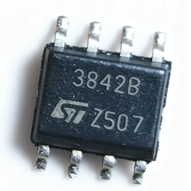
UC3842BD1 - Current Mode PWM Controller | STMicroelectronics | SMPS
The STMicroelectronics UC3842BD1 is a high-performance current-mode PWM controller designed for off-line and DC-to-DC converter applications. It operates with an input voltage range of 7.5V to 30V and provides a 1A peak output current for driving power MOSFETs. The device is available in an SOIC-8 package, making it suitable for compact power supply designs. A current-mode PWM controller is a type of switching regulator control IC that regulates output voltage by comparing the output error signal with a current-sense signal from the power switch. This architecture provides inherent feed-forward compensation, cycle-by-cycle current limiting, and simplified loop compensation compared to voltage-mode controllers. The UC3842BD1 belongs to the UC3842 family of PWM controllers, which are widely used in AC-DC adapters, battery chargers, and industrial power supplies. Key features of the UC3842BD1 include a trimmed oscillator for precise frequency control, an under-voltage lockout (UVLO) with hysteresis, a 5V reference output, and a high-gain error amplifier. The oscillator frequency is programmable up to 500 kHz, allowing designers to optimize transformer size and efficiency. The device also features a low startup current of 0.5 mA, which is critical for efficient power-up in battery-powered systems. The UC3842BD1 uses a fixed-frequency current-mode architecture with a maximum duty cycle of 96%. The error amplifier has a bandwidth of 1 MHz, enabling fast transient response. The current-sense comparator has a threshold of 1V, providing accurate cycle-by-cycle current limiting. The device is designed to operate over a junction temperature range of -40°C to +150°C, ensuring reliability in harsh environments. Typical applications include switch-mode power supplies (SMPS) for consumer electronics, industrial power converters, and battery chargers. The UC3842BD1 is also used in flyback and boost converter topologies, where its current-mode control simplifies loop compensation and improves line regulation. When designing with the UC3842BD1, ensure that the current-sense resistor is placed close to the IC to minimize parasitic inductance. The oscillator timing resistor and capacitor should be located near the RT/CT pin to reduce noise coupling. Proper grounding and decoupling of the VCC pin are essential for stable operation. This page synthesizes distributor pricing, drop-in alternatives, and practical design notes not found in the STMicroelectronics datasheet, providing engineers with a comprehensive resource for selecting and implementing the UC3842BD1.

UC3842BD1013TR - Current Mode PWM Controller | STMicroelectronics
The UC3842BD1013TR is a high-performance current-mode PWM controller from STMicroelectronics, designed for off-line and DC-to-DC converter applications. It operates as a boost or flyback regulator with isolation capability, providing a cost-effective solution for power supply designs. The device is housed in an 8-SOIC package and supports a switching frequency up to 500 kHz, with a peak output current of 1 A. Its input voltage is rated at 15 V, and it operates over a temperature range of 0°C to 70°C. A current-mode PWM controller is a type of switching regulator controller that uses the inductor current as a feedback signal to modulate the duty cycle of the output switch. This architecture provides inherent cycle-by-cycle current limiting, improved transient response, and simplified loop compensation compared to voltage-mode controllers. The UC3842BD1013TR belongs to the UC3842 family, which is widely used in AC-DC adapters, battery chargers, and isolated DC-DC converters. Key features of the UC3842BD1013TR include a trimmed oscillator for precise frequency control, current-mode operation up to 500 kHz, automatic feed-forward compensation, latching PWM for cycle-by-cycle current limiting, and an internally trimmed reference. These features enable stable and reliable operation in demanding power conversion applications. The device also includes under-voltage lockout (UVLO) and a totem-pole output stage capable of sourcing and sinking 1 A peak current to drive power MOSFET gates directly. Technically, the UC3842BD1013TR integrates a 5V reference, an error amplifier, a current-sense comparator, and a PWM latch. The oscillator frequency is set by an external resistor and capacitor, allowing designers to program the switching frequency from 50 kHz to 500 kHz. The current-sense input provides overcurrent protection by comparing the sensed voltage to a 1V threshold. The device's low startup current and low operating current contribute to high efficiency in power supplies. Typical applications include switch-mode power supplies (SMPS) for consumer electronics, industrial power converters, and isolated flyback converters for telecom and networking equipment. The UC3842BD1013TR is particularly suited for designs requiring a simple, reliable current-mode controller with minimal external components. When designing with this controller, ensure proper PCB layout to minimize noise on the current-sense and feedback paths. Use a low-ESR capacitor on the VCC pin and place the timing components close to the IC. Adequate thermal relief on the SOIC package is recommended for high-power applications.

UCC20225QNPLRQ1 - Automotive 4A/6A Dual Isolated Gate Driver | TI
The Texas Instruments UCC20225QNPLRQ1 is an automotive-grade (AEC-Q100 qualified) isolated single-input, dual-output gate driver with 4-A source and 6-A sink peak current, housed in a 13-pin VLGA (NPL) 5-mm x 5-mm package. It is designed to drive power transistors up to 5-MHz with best-in-class propagation delay and pulse-width distortion, and provides a 2.5-kV RMS reinforced isolation barrier between the input side and the two output drivers. A gate driver is a power amplifier that accepts a low-power logic-level PWM command from a controller and produces the high-current drive signal required to switch a power MOSFET, IGBT, or GaN/SiC transistor. Isolated gate drivers add a galvanic isolation barrier between the low-voltage control domain and the high-voltage power domain, protecting the controller and meeting safety creepage/clearance requirements in high-voltage systems. The UCC20225QNPLRQ1 sits inside the broader hierarchy of gate driver -> power management IC -> semiconductor, and is specifically tuned for high-side/low-side or half-bridge topologies with a single PWM input. Key features include 4-A source / 6-A sink peak drive, 30-ns typical propagation delay, 5-ns maximum channel-to-channel delay matching, minimum 100-V/ns common-mode transient immunity (CMTI), and an 8-V undervoltage lockout (UVLO) optimized for automotive 48-V systems. The VLGA-13 footprint occupies only 25 mm^2 of board area, enabling compact half-bridge and bootstrap designs in tight enclosures. The architecture combines a single CMOS/digital input with two independently isolated output channels, each capable of sinking/sourcing gate charge at MHz switching speeds. An integrated dead-time control feature and the 8-V UVLO threshold make this part particularly well-suited to automotive 48-V traction, OBC, and DC-DC converter stages using GaN or Si MOSFETs that need tight threshold management to prevent partial turn-on. Typical applications include 48-V mild-hybrid DC-DC converters, traction inverter gate-drive stages, on-board chargers (OBC), and isolated half-bridge power stages for industrial motor drives. Its 8-V UVLO specifically targets the 12-V class gate-drive rails common in 48-V automotive systems. When designing with this driver, place the bootstrap diode and capacitor directly adjacent to the high-side output pins to minimize parasitic inductance; insufficient decoupling on VDD can couple switching noise back into the logic input and cause spurious UVLO events at high dV/dt. This page synthesizes distributor pricing, drop-in alternatives, automotive 48-V application notes, and pin-by-pin design considerations beyond the manufacturer datasheet summary, helping power engineers accelerate ISO 26262-compliant design reviews.

UCC21520 - 4A/6A 5.7kVRMS Isolated Dual Gate Driver | TI
The Texas Instruments UCC21520 is an isolated dual-channel gate driver delivering 4-A source and 6-A sink peak output current, engineered to drive power MOSFETs, IGBTs, and SiC MOSFETs at switching frequencies up to 5 MHz with 5.7-kVRMS reinforced isolation in a 16-pin SOIC (DW) package. An isolated gate driver is an IC that combines galvanic isolation and signal amplification between a low-voltage controller and high-voltage power switches. Within the power management IC hierarchy, it sits between logic-level drivers and full gate-drive optocoupler solutions, enabling safe control of high-side and low-side switches in half-bridge, full-bridge, and LLC topologies. Key features include a wide VDD range of 6.5V to 25V, TTL/CMOS-compatible input thresholds, a DIS disable pin for output control, and UVLO protection on all supply pins. The device achieves a 19-ns propagation delay and 6-ns pulse-width distortion, best-in-class figures that preserve PWM accuracy at high switching frequencies. Technically, the UCC21520 uses TI capacitive isolation technology providing 100 V/ns common-mode transient immunity (CMTI), which prevents false triggering from fast dv/dt switching edges typical of SiC and GaN power stages. Programmable dead time via resistor setting and interlock function prevent shoot-through in bridge configurations. Typical applications include solar inverters, motor drives, EV charging and on-board chargers, isolated DC-DC converters, and UPS power stages, where high peak current efficiently charges large gate capacitances. Design tip: provide tight VDDA/VDDB decoupling and minimize gate-loop parasitic inductance; PCB layout critically affects realized CMTI and gate ringing performance.
UCC21520Q-Q1 - 4A/6A 5.7kVRMS Isolated Dual Gate Driver | TI
The Texas Instruments UCC21520Q-Q1 is an AEC-Q100 qualified, isolated dual-channel gate driver delivering 4-A source and 6-A sink peak output current. It drives power MOSFETs, IGBTs, and SiC MOSFETs at switching frequencies up to 5 MHz, with a 5.7 kVRMS reinforced capacitive isolation barrier providing a minimum of 125 V/ns common-mode transient immunity (CMTI). The device comes in a 16-pin wide-body SOIC (DW) surface-mount package. An isolated gate driver is a power-management IC that transfers a low-voltage logic-level PWM signal across a galvanic isolation barrier to drive the gate of a power semiconductor floating at high voltage. Within the signal-chain hierarchy, it sits between the PWM controller or microcontroller and the power stage, combining the functions of a logic buffer, level shifter, and isolation barrier in a single device. Key features include best-in-class propagation delay and pulse-width distortion, TTL- and CMOS-compatible input thresholds on INA, INB, and DIS pins that are independent of VDD, under-voltage lockout (UVLO) protection on all supply pins, and flexible dual-input configuration that allows the device to fit half-bridge, full-bridge, and dual low-side or high-side topologies. The 8-V UVLO variant ensures gate-drive integrity with SiC MOSFETs that require higher gate-source thresholds. The capacitive isolation architecture uses an on-chip SiO2 barrier delivering reinforced isolation rated at 5.7 kVRMS, supporting functional safety requirements in automotive traction inverters, onboard chargers, and high-voltage servo drives. High CMTI tolerance allows reliable operation in the presence of fast dv/dt switching edges typical of GaN and SiC power stages. Typical applications include automotive traction inverters, 48 V and high-voltage DC-DC converters, onboard chargers, solar string inverters, and industrial motor drives using SiC or IGBT power modules. When designing, verify that the VDDA/VDDB UVLO threshold matches the gate-drive voltage requirements of the selected power switch, and keep the gate-drive loop inductance minimal with closely coupled return paths.
UCC21521 - 4A/6A 5.7kVrms Isolated Gate Driver | TI
The Texas Instruments UCC21521 is an isolated dual-channel gate driver with 4-A source and 6-A sink peak output current, designed to drive power MOSFETs, IGBTs, and SiC MOSFETs at switching frequencies up to 5 MHz. It provides a reinforced isolation barrier of 5.7-kV RMS with at least 100-V/ns common-mode transient immunity (CMTI) in a 16-pin SOIC (DW) package. An isolated gate driver is a power management IC that translates low-voltage control logic into the high gate-drive current required to switch power transistors while maintaining galvanic isolation between controller and power stage. Within the power electronics hierarchy it sits between PWM controllers (DSPs, microcontrollers) and the power semiconductors they control, and is essential for safety and noise immunity in high-voltage converters. Key features include 19-ns typical propagation delay, 10-ns minimum pulse width, 5-ns maximum delay matching, and 6-ns maximum pulse-width distortion. These timing parameters enable precise, synchronized switching that reduces switching losses and EMI. Programmable dead time prevents shoot-through in half-bridge configurations, and the DIS enable pin supports power sequencing and fault protection. The UCC21521 uses TI capacitive isolation technology delivering CMTI of at least 100 V/ns for reliable operation in high-dv/dt environments such as SiC-based converters. Input pins use TTL and CMOS-compatible thresholds, allowing direct interface with 3.3-V microcontrollers and DSPs. The universal architecture supports dual low-side, dual high-side, or half-bridge driver configurations, and the device operates from -40C to +125C. Typical applications include motor drives, solar inverters, EV onboard chargers, and isolated DC-DC converters, where the 4-A/6-A drive strength and 5-MHz capability suit SiC MOSFET and IGBT power stages. Design tip: place decoupling capacitors close to VCCI and VDDA/VDDB pins and minimize gate-loop parasitic inductance to achieve specified timing performance and avoid dv/dt-induced false triggering.
UCC21521ADW - 4A/6A 5.7kVrms Isolated Gate Driver | TI
The Texas Instruments UCC21521ADW is a 4-A source / 6-A sink dual-channel isolated gate driver with 5.7-kVRMS galvanic isolation, capacitive coupling, an enable pin, programmable dead time, and 8-V UVLO, housed in a 16-pin SOIC (DW) package. An isolated gate driver is a power management IC that translates low-voltage logic signals across a galvanic isolation barrier to drive the gate of a power semiconductor such as a MOSFET, SiC FET, or IGBT. Within the power-supply and motor-control hierarchy, it sits between the PWM controller or microcontroller and the power stage, providing both the high peak currents needed for fast switching and the reinforced isolation needed for safety and level shifting. Key features include the universal configuration supporting dual low-side, dual high-side, or half-bridge operation, fast 19-ns typical propagation delay, 10-ns minimum input pulse width, and 5-ns maximum interchannel delay matching. The 4-A/6-A asymmetric source/sink drive accelerates turn-off to reduce switching losses in hard-switched converters. A programmable dead-time feature prevents shoot-through in half-bridge topologies, and the enable pin allows global shutdown for fault handling. The device uses TI capacitive isolation technology with a 5700-Vrms working isolation rating and 8-V undervoltage lockout on the output-side supply to guarantee complete gate enhancement before operation. Operating temperature spans -40C to +125C, supporting industrial power conversion, motor drives, solar inverters, and on-board chargers. Typical applications include half-bridge and full-bridge stages in server and telecom power supplies, three-phase inverters in motor drives, and isolated DC-DC converters where fast, precisely matched gate drive improves efficiency. For design, ensure the output-side VDD meets the 8-V UVLO threshold with adequate local decoupling, and size the dead time for the target power switch. This page synthesizes distributor pricing, drop-in alternatives, and practical design notes not found in the manufacturer datasheet.
UCC21521ADWR - 5.7kVrms 4A/6A Isolated Gate Driver | TI
The Texas Instruments UCC21521ADWR is a reinforced isolated dual-channel gate driver delivering 4-A source and 6-A sink peak output current with a 5700-Vrms withstand isolation rating, housed in a 16-pin SOIC (DW) package. It features dual inputs with an enable pin, an 8-V UVLO option, and programmable dead time, and can be configured as a dual low-side driver, dual high-side driver, or half-bridge driver. An isolated gate driver is a power management IC that transfers control signals across a galvanic isolation barrier, allowing a controller on the low-voltage side to switch power transistors such as MOSFETs, IGBTs, and SiC or GaN devices connected to a high-voltage rail. Isolated gate drivers sit within the broader gate driver and power management IC hierarchy and are essential wherever the gate-referenced potential differs from the logic-referenced potential. Key differentiating specifications include the 5.7-kVRMS reinforced isolation rating per the capacitive isolation technology, the asymmetric 4-A source / 6-A sink drive strength that favors fast turn-off for switch protection, and a wide supply range with an 8-V UVLO threshold suited to SiC MOSFET gate driving. The enable pin supports system-level safety interlocks, and the dead-time control eases half-bridge design. Architecturally, the UCC21521 uses a capacitive isolation barrier with on-chip signal isolation across a silicon-dioxide dielectric, providing high CMTI performance for switching noise immunity. The two output channels share a common topology with independent inputs, supporting inverting or non-inverting configurations depending on the ordering variant and input polarity. Typical applications include motor drives and industrial inverters, solar string inverters and MPPT power stages, and on-board chargers or DC-DC power stages in industrial power systems. The 4-A/6-A drive strength matches medium-power SiC and IGBT modules where fast gate charge delivery reduces switching losses. Design consideration: verify the input-side supply (VCCI) logic threshold matches the MCU or DSP bank voltage, and route the high-voltage side with adequate creepage and clearance per the reinforced-isolation footprint of the DW-16 package. This page synthesizes verified distributor pricing, drop-in alternatives, and practical design notes not consolidated in the manufacturer datasheet alone.
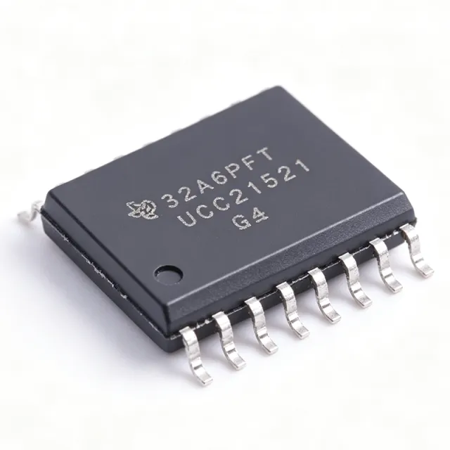
UCC21521DWR - 4A/6A 5.7kVrms Isolated Gate Driver | TI
The Texas Instruments UCC21521DWR is a 4-A source / 6-A sink dual-channel reinforced isolated gate driver with 5.7-kV RMS galvanic isolation, at least 100 V/ns common-mode transient immunity (CMTI), and a 16-pin SOIC (DW) package. An isolated gate driver is a power-management IC that translates low-voltage control logic from a microcontroller or DSP into the high peak current required to switch power transistors, while maintaining galvanic isolation between the control side and the power stage. Within the power-electronics hierarchy it sits between PWM controllers and MOSFETs, IGBTs, or SiC MOSFETs, and it is essential for safety isolation and noise immunity in high-voltage converters. Key features include 19-ns typical propagation delay, 5-ns maximum channel-to-channel matching, 6-ns maximum pulse-width distortion, and a 10-ns minimum input pulse width. These tight timing specifications reduce switching losses and minimize shoot-through risk. The DIS enable pin supports power sequencing and fast fault shutdown, and programmable dead time (for half-bridge configurations) prevents cross-conduction. Technically, the UCC21521 uses TI capacitive isolation technology to deliver the 5.7-kV RMS reinforced barrier with CMTI of at least 100 V/ns, making it robust in high dv/dt SiC environments. Input thresholds are TTL and CMOS compatible for direct 3.3-V logic interfacing, and an 8-V UVLO protects the power switch from under-driven operation. Typical applications include motor drives, solar string inverters, EV onboard chargers, and isolated DC-DC converters, where the 4-A/6-A drive strength and up-to-5-MHz switching capability suit SiC and IGBT power stages. Design tip: place decoupling capacitors directly at VCCI and VDDA/VDDB pins and minimize gate-loop inductance to achieve the datasheet timing figures and avoid dv/dt-induced false triggering. This page adds value beyond the datasheet with drop-in alternative comparisons, pricing tiers, and practical layout notes synthesized from distributor and manufacturer data.
UCC21521Q-Q1 - 4A/6A 5.7kVRMS Dual Gate Driver | Texas Instruments
The Texas Instruments UCC21521Q-Q1 is an AEC-Q100 qualified, 5.7-kVRMS isolated dual-channel gate driver delivering 4-A source and 6-A sink peak output current, housed in a 16-pin SOIC (DW) package. The device is universal in topology, supporting dual low-side, dual high-side, or half-bridge driver configurations, and includes an enable pin for system-level control. An isolated gate driver is a power management IC that provides galvanic isolation between the low-voltage controller side and the high-voltage power stage, allowing a microcontroller to safely drive power semiconductor switches such as MOSFETs, SiC FETs, and IGBTs. Gate drivers form the interface layer of the power-conversion hierarchy: controller -> signal isolator -> gate driver -> power switch. Key features include capacitive-coupled isolation rated at 5700 Vrms, high CMTI (common-mode transient immunity) for fast-switching wide-bandgap applications, a UVLO (undervoltage lockout) on both input and output supplies that prevents erratic gate drive during power-up, and an enable pin that places both outputs low for safety interlocks. The 4-A/6-A asymmetrical drive strength provides strong turn-off capability that minimizes switching losses and improves dv/dt immunity against parasitic turn-on. The Q1 grade guarantees operation from -40C to +125C ambient under AEC-Q100 automotive qualification, making the device suited to traction inverters, on-board chargers, and 48V systems. The universal channel configuration lets a single bill-of-material position cover half-bridge, dual low-side, and dual high-side designs, reducing qualification overhead across platforms. Typical applications include automotive traction inverters, OBC PFC and LLC power stages, DC fast-charger modules, solar string inverters, and industrial motor drives driving SiC or IGBT switches. The wide-body creepage and clearance of the SOIC-16 (DW) package supports reinforced isolation designs. Design consideration: size the gate-loop resistance to balance switching speed against ringing, and place the driver close to the power switch to minimize loop inductance; always verify CMTI margin against the fastest dv/dt in the system. Pricing data as of 2026-08-29; see tiers below for quantity pricing.

UCC21530 - 4A/6A 5.7kVRMS Isolated Dual Gate Driver | TI
The Texas Instruments UCC21530 is an isolated dual-channel gate driver delivering 4A source and 6A sink peak output current in a 14-pin SOIC (DWK) package. It is designed to drive IGBTs, Si MOSFETs, and SiC MOSFETs at switching frequencies up to 5MHz, with a 5.7kVRMS reinforced isolation barrier and a minimum common-mode transient immunity (CMTI) of 125V/ns. An isolated gate driver is a specialized power-management IC that provides galvanic isolation between a low-voltage controller (MCU or PWM controller) and a high-voltage power stage while supplying the peak current required to switch power transistors rapidly. It sits in the power electronics signal chain between the digital controller and the gate of an IGBT or MOSFET. The UCC21530 uses a capacitive isolation architecture, which enables high-speed signal transfer with low power consumption compared with optocoupler-based drivers. Key features include 4A/6A peak output current, 5.7kVRMS reinforced isolation, 125V/ns minimum CMTI, 3.3mm channel-to-channel spacing, an enable pin, and programmable dead time via the DT pin. According to the TI datasheet, the device offers best-in-class propagation delay and low pulse-width distortion, which reduces dead-time losses and enables precise, efficient switching. Undervoltage lockout (UVLO) on both the input and output sides adds system-level robustness. Architecturally, the UCC21530 comprises an input-side controller coupled through a capacitive isolation barrier to two secondary-side drivers. The reinforced barrier supports demanding safety standards, while internal functional isolation between the two outputs allows independent high-side and low-side operation in half-bridge and full-bridge configurations without external isolation components. Typical applications include three-phase motor drives, solar string inverters, EV onboard chargers, UPS systems, and server power supplies. High peak current and low propagation delay minimize switching losses, while high CMTI prevents false gate triggering at rapidly slewing switch nodes in SiC designs. When designing with the UCC21530, minimize gate-loop parasitic inductance, set dead time correctly via the DT pin to prevent shoot-through, and verify UVLO thresholds against your rail-sequencing plan for reliable startup. Pricing as of 2026-08-30 is available from authorized distributors listed in data sources.

UCC21530DWKR - 4A/6A Dual-Channel Isolated Gate Driver | TI
The Texas Instruments UCC21530DWKR is a 4A source / 6A sink, 5.7 kVRMS reinforced-isolated dual-channel gate driver in a 14-pin SOIC (DWK) package with 3.3 mm channel-to-channel spacing. It is engineered to drive IGBTs, silicon MOSFETs, and SiC MOSFETs up to 5 MHz switching frequency, with a minimum 125 V/ns common-mode transient immunity (CMTI) rating. A galvanically isolated gate driver is a power-semiconductor interface IC that translates low-voltage PWM control signals from a digital controller (MCU, DSP, or FPGA) into the high-voltage, high-current drive required to switch the gate of a power transistor. It belongs to the broader hierarchy of gate driver -> power management IC -> signal conditioning -> power conversion. Reinforced isolation, defined by IEC 60747-17, provides a 5.7 kVRMS working voltage plus transient overvoltage protection between the low-voltage primary side and the high-voltage secondary side, eliminating the need for optocouplers or external bootstrap circuits in many topologies. Key features include 4 A peak source / 6 A peak sink drive capability, 5.7 kVRMS reinforced isolation per UL 1577, 8 V to 18 V VDD supply range (VDDA/VDDB up to 25 V), programmable dead-time control via the DT pin, an enable pin for simultaneous shutdown of both outputs, internal functional isolation between the two secondary sides, and an extended -40C to +125C operating temperature range. The wide drive-voltage capability supports SiC MOSFET turn-on enhancement and IGBT gate-charge requirements across many power classes. The device employs TI's capacitive isolation technology using an internal SiO2 dielectric barrier, achieving CMTI of at least 125 V/ns and supporting switching frequencies up to 5 MHz. Fail-safe logic ensures that primary-side faults force both outputs LOW, preventing catastrophic half-bridge shoot-through conditions in motor drive and inverter applications. Typical applications include solar inverters, industrial motor drives (AC induction, BLDC, PMSM), telecom DC/DC converters using DAB/PSFB topologies, EV charging stations (OBC and DC fast charge), SiC FET-based high-frequency converters, and Class D audio amplifiers. The reinforced isolation barrier also allows direct drive of 600 V / 1200 V / 1700 V class power stages without additional isolation. When designing with the UCC21530DWKR, choose decoupling capacitors of at least 1 uF low-ESR ceramic on each VDD rail placed within 5 mm of the IC pins. The DT pin resistor sets dead time and must be selected based on the specific power-switch turn-off delay to prevent cross-conduction; consult the datasheet's dead-time programming section for the recommended resistor range. This page synthesizes distributor pricing, parametric drop-in alternatives, and practical PCB layout notes not consolidated on the manufacturer datasheet front page, providing engineers with a single decision-ready reference.

UCC21530Q-Q1 - 4A/6A 5.7kVRMS Isolated Gate Driver | TI
The Texas Instruments UCC21530Q-Q1 is an AEC-Q100 qualified, reinforced isolated dual-channel gate driver delivering 4A source and 6A sink peak output current, designed to drive IGBTs, Si MOSFETs, and SiC MOSFETs at switching frequencies up to 5MHz. It comes in a 14-pin SOIC (DWK) package with a 5.7kVRMS reinforced isolation barrier providing 3.3mm channel-to-channel spacing. An isolated gate driver is a power management IC that transfers logic-level PWM control signals across a galvanic isolation barrier to drive the gate of a high-side or low-side power switch floating at high voltage. Within the power-electronics hierarchy (gate driver -> isolated driver IC -> power management IC -> semiconductor), the UCC21530-Q1 occupies the critical interface between a microcontroller such as the TMS320F28004x C2000 family and the power stage. Key features include best-in-class propagation delay and pulse-width distortion, programmable dead time via a single DT pin resistor, a common-mode transient immunity (CMTI) of at least 125V/ns for operation on fast-switching GaN and SiC bridges, and TTL/CMOS-compatible input thresholds independent of the VDDI supply. An enable pin allows global shutdown, and both outputs can be interlocked for half-bridge configurations. The capacitive isolation architecture supports a maximum repetitive peak isolation voltage suitable for 800V-class automotive systems such as on-board chargers and traction inverters, though designers should verify creepage requirements against the 3mm package spacing. Wide VDDI operation on the output side accommodates 5V-to-20V gate-drive rails needed for SiC MOSFETs. Typical applications include automotive traction inverters, 800V on-board chargers (OBC), DC-DC converters, motor drives, and solar inverters. Pairing the driver with SiC MOSFETs such as the LMG3422 GaFET ecosystem or discrete SiC switches yields low-loss, high-frequency power stages. Design tip: size the DT-pin resistor precisely to set dead time, and place a low-ESR decoupling network (1uF plus 100nF) directly at VDDA and VDDB to sustain 4A/6A peak gate currents without droop.
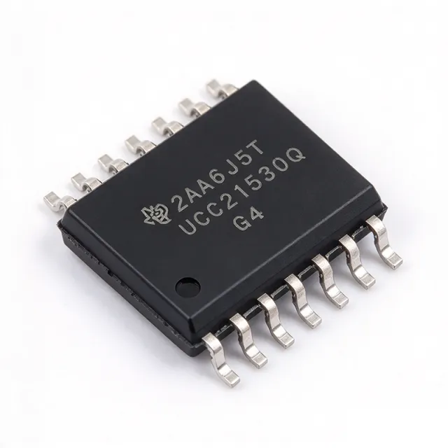
UCC21530QDWKRQ1 - 4A/6A 5.7kVrms Isolated Gate Driver | TI
The Texas Instruments UCC21530QDWKRQ1 is an automotive-grade, 4-A source / 6-A sink, 5.7-kVRMS reinforced isolated dual-channel gate driver with enable and programmable deadtime, housed in a 14-pin DWK (SOIC-14 wide-body) package. It drives IGBTs, SiC MOSFETs, and GaN power switches up to 5 MHz with best-in-class propagation delay (33 ns typical) and pulse-width distortion. The reinforced isolation barrier is rated to 5.7 kVRMS with a minimum 8.5-mm creepage / clearance and 3.3-mm channel-to-channel spacing, simplifying UL 1577 and IEC 60747-17 compliance for high-voltage systems. An isolated gate driver is a switching power-supply sub-system that translates low-side logic-level PWM into a high-voltage, floating gate-drive signal referenced to the switched-node of a half-bridge. It belongs to the gate-driver IC family, a category within power MOSFET/IGBT drivers, under the broader power management hierarchy. The UCC21530-Q1 integrates a silicon-oxide isolation transformer, two output channels (the chip itself), and is AEC-Q100-qualified for automotive environments by design. Key features include 4-A peak source and 6-A peak sink output current, a wide 18-V to 25-V VDD/VDDA range (3-V to 18-V on logic side), 33-ns typical propagation delay, 5-ns maximum channel-to-channel delay matching, 100-V/ns CMTI, and integrated programmable deadtime (DT) for shoot-through prevention. An active-low enable pin and a fault-ready open-drain output support sequencing and desaturation monitoring in three-phase inverters and PFC stages. Typical applications include traction inverters for EV powertrains, on-board chargers (OBC), industrial servo drives, solar string inverters, telecom DC/DC converters, and any 400-V / 800-V bus half-bridge topology requiring reinforced isolation. The DWK wide-body SOIC package provides 8.5 mm of creepage for high-voltage pollution-degree-2 environments. When designing with the UCC21530-Q1, place 1-uF / 100-nF decoupling on VDD/VDDA/VCCI close to the IC pins. Use a bootstrap diode + capacitor on the high-side channel whose voltage rating is rated for the DC bus plus transient ringing. Always respect the absolute-maximum VDD/VDDA of 30 V to avoid catastrophic gate-oxide damage. This page synthesizes distributor pricing, drop-in alternatives, and practical design notes not consolidated in the manufacturer datasheet — including same-package TI options, cross-brand validation notes, and BOM-optimization guidance unavailable on DigiKey/Mouser product pages.
UCC21540 - 4A/6A 5.7kVRMS Isolated Gate Driver | Texas Instruments
The Texas Instruments UCC21540 is a reinforced isolated dual-channel gate driver delivering up to 4-A peak source and 6-A peak sink current to drive power MOSFETs, IGBTs, and GaN transistors. It carries a 5.7-kVRMS galvanic isolation rating, and the DWK package option provides 3.3-mm channel-to-channel spacing for high bus-voltage industrial designs. An isolated gate driver is a specialized IC that provides galvanic isolation between a low-voltage controller and a high-voltage power stage, enabling safe, ground-loop-free switching of power transistors in the power-conversion hierarchy: gate driver -> isolated driver -> power management IC. The UCC21540 belongs to the UCC2154x family within TI's broad isolated gate driver portfolio, optimized for 10-12V driven MOSFETs and IGBTs. Key features include 4-A/6-A peak drive strength, 5.7-kVRMS reinforced isolation per the capacitive isolation technology, a programmable-deadtime (DT) pin that prevents shoot-through in half-bridge configurations, a disable (DIS) pin for system-level fault shutdown, and an 8-V UVLO on the secondary-side supply. VDD on the output side operates from 6.5V to 18V, supporting both dual low-side and half-bridge topologies. Technically, the device uses TI capacitive isolation technology, delivering fast propagation delay, low channel-to-channel matching error, and high common-mode transient immunity (CMTI), which is essential when switching at high frequency across large dv/dt events such as GaN half-bridge transitions. The dual-input configuration accepts both PWM-style inverting/non-inverting inputs for flexible control interfacing. Typical applications include server and telecom power supplies, industrial motor drives, solar string inverters, and EV onboard chargers, where its combination of drive strength, deadtime control, and isolation robustness maximizes converter efficiency and reliability. Design tip: keep the gate-drive loop compact, set the DT pin resistor for the deadtime your switches require, and respect creepage/clearance spacing on the PCB. According to TI, pricing and availability as of 2026-08-30.
UCC21540ADWR - 4A/6A Dual Isolated Gate Driver, 14-SOIC | TI
The Texas Instruments UCC21540ADWR is a 4A/6A dual-channel reinforced isolated gate driver with disable pin and programmable dead time, housed in a 14-pin SOIC (DW) package. The driver delivers 4A peak source and 6A peak sink current, supports up to 5.7kVrms galvanic isolation, and operates across an industry-standard 3V to 18V VCC range, making it suitable for driving power MOSFET, IGBT, and GaN transistors in half-bridge, dual low-side, or dual high-side configurations. An isolated gate driver is a semiconductor device that provides galvanic isolation between a low-voltage control circuit (such as a microcontroller or DSP) and a high-voltage power stage. By using capacitive or magnetic isolation barriers, these drivers protect low-voltage logic from high-voltage transients while delivering the high peak currents required to rapidly switch power FET gates. The UCC21540ADWR belongs to the isolated gate driver category, a sub-family of power management ICs that sits between MCU/DSP controllers and the discrete power switches in converters, motor drives, and solar inverters. Key features include 4A source / 6A sink peak drive current, 5.7kVrms basic isolation (per UL 1577), 1500Vrms working voltage, programmable dead time from 0 to several hundred nanoseconds via a single external resistor, and an active-low DISABLE pin for synchronized shutdown. The device supports up to 25V VDD supply for gate drive rails, and its dual-channel architecture permits independent control of high-side and low-side FETs in a half-bridge topology. The UCC21540ADWR uses TI's capacitive isolation technology with an integrated transformer driver on-chip, providing robust common-mode transient immunity (CMTI) and eliminating the need for optocouplers. The internal architecture includes a PWM input stage, oscillator, isolation barrier, and output buffer stages optimized for fast propagation delay (typically under 40ns) and minimal channel-to-channel skew, both critical for high-frequency switch-mode power supply designs. Typical applications include solar inverters, industrial motor drives, telecom brick converters, server and telecom power supplies, EV charging stations, and UPS systems. The wide VCC range also supports battery-powered portable equipment driving 12V to 48V bus rails. When designing with this part, observe that the disable pin (pin 6) defaults to a defined logic level - leave it tied high if unused. Dead-time programming resistor selection must be verified against the actual switching frequency, and a small bypass capacitor (typically 1nF to 10nF) is recommended near VCC and VDD supplies. This page synthesizes distributor pricing, drop-in alternatives (including same-family UCC21540DWK in the larger SOIC-16 DWK footprint), and practical design notes that complement the manufacturer datasheet.
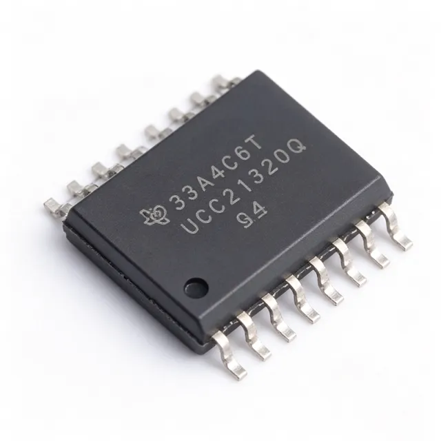
UCC21540QDWKRQ1 - 5.7kVRMS Isolated Dual Gate Driver | Texas Instruments
The Texas Instruments UCC21540QDWKRQ1 is an automotive-grade, AEC-Q100 qualified, reinforced-isolated dual-channel gate driver delivered in a 14-pin SOIC (DWK) package. It provides 4 A peak-source and 6 A peak-sink output current to drive power MOSFET, IGBT, and GaN transistors, with 5700 VRMS galvanic isolation based on capacitive coupling and programmable dead time for half-bridge configurations. An isolated gate driver is a power-management IC that transfers control signals across a galvanic isolation barrier, allowing a controller on the low-voltage side to safely switch power transistors floating at high potential. Isolated gate drivers sit within the broader hierarchy of gate drivers, power management ICs, and semiconductors, and are essential building blocks in any switched-mode power conversion system where the switch node is referenced to a high-voltage rail. Key features include 5700 VRMS reinforced isolation, 8-V UVLO on the secondary side, configurable dual inputs allowing the device to operate as two low-side drivers, two high-side drivers, or a half-bridge driver with independent or interlocked control, and programmable dead time implemented via a single external resistor. The DWK package offers 3.3-mm minimum channel-to-channel spacing for reinforced isolation and a wide operating temperature range suited to automotive under-hood environments. Architecturally, the device uses TI capacitive isolation technology, which provides faster and more consistent propagation delay than optocoupler-based drivers, along with robust common-mode transient immunity. Consistent performance under extreme temperature conditions makes the -Q1 variant suitable for traction inverters, onboard chargers, and other automotive power systems. Typical applications include EV traction inverter half-bridges driving IGBT or SiC/GaN modules, onboard charger and DC-DC converter power stages, solar string inverters, and industrial motor drives. The 4 A/6 A drive strength is well matched to medium-power switches requiring fast turn-off to minimize switching losses. Design tip: size the dead-time resistor precisely and place a low-ESR decoupling capacitor directly across VDDA/VSSA and VDDB/VSSB; verify that the CMTI rating covers the expected dV/dt of your switch node to prevent spurious output transitions.
UCC21550 - 4A/6A 5kVrms Isolated Dual Gate Driver | TI
The Texas Instruments UCC21550 is a reinforced isolated dual-channel gate driver delivering 4A peak-source and 6A peak-sink current to drive power MOSFETs, SiC, GaN, and IGBT transistors. Housed in a 16-pin SOIC (DW) package, it provides 5000Vrms reinforced isolation per UL1577 and operates across a wide -40C to +150C temperature range. The device can be configured as two low-side drivers, two high-side drivers, or a half-bridge driver. An isolated gate driver is an integrated circuit that supplies the gate charge current needed to switch power transistors while maintaining galvanic isolation between the low-voltage controller and the high-voltage power stage. Within the power management hierarchy (gate driver -> isolated gate driver -> power management IC), isolation is critical for safety, noise immunity, and level-shifting in high-voltage systems such as motor drives and solar inverters. Key features include the high 4A/6A peak currents that rapidly charge and discharge large gate capacitances, reducing switching losses in SiC and GaN converters. Programmable dead time, set by a resistor on the DT pin, prevents shoot-through in half-bridge topologies. Capacitive silicon-dioxide isolation technology provides high common-mode transient immunity (CMTI), essential when switching fast SiC devices at high dv/dt. Undervoltage lockout (UVLO) on both input and output supplies protects against brownout conditions, and the family offers multiple UVLO and dead-time grade options (A/B/C variants). Technically, the UCC21550 transfers PWM signals across a capacitive isolation barrier with low propagation delay and tight channel-to-channel matching, according to TI datasheet UCC21550 (46 pages). Typical applications include switch-mode power supplies, solar string inverters, motor drives, EV onboard chargers, and industrial power conversion. The wide temperature range and reinforced isolation suit automotive and industrial environments (an AEC-Q100 qualified UCC21550x-Q1 family is available). Design tip: place the driver close to the power transistors to minimize gate-loop parasitic inductance, and size the DT resistor dead time to the switching characteristics of the connected transistors to prevent shoot-through.
UCC21550ADWR - 4A/6A Isolated Dual Gate Driver | Texas Instruments
The Texas Instruments UCC21550ADWR is a 5000Vrms reinforced-isolated dual-channel gate driver with 4A peak source and 6A peak sink output current, programmable dead time, and CMTI greater than 125 V/ns, housed in a 16-pin SOIC (DW) package. An isolated gate driver is a power management IC that translates low-voltage logic signals across a galvanic isolation barrier to drive the gate of a power transistor such as a MOSFET, SiC MOSFET, GaN FET, or IGBT. Within the power-conversion hierarchy, it sits between the PWM controller or microcontroller and the power stage, providing both the current amplification needed to switch power devices quickly and the isolation needed to shift logic references to high-side or floating switch nodes safely. Key features include configurable operation as two low-side drivers, two high-side drivers, or a half-bridge driver; a wide VDD output supply range up to 25V; a 5V undervoltage lockout (UVLO) option; and an integrated DISABLE pin for immediate output control. The capacitive-coupling isolation architecture delivers high common-mode transient immunity, critical for SiC and GaN converters whose fast switching edges (dV/dt exceeding 100 V/ns) would corrupt optocoupler-based drivers. Technically, the UCC21550 uses TI capacitive isolation technology with on-chip logic that supports programmable dead time via an external resistor, protecting half-bridge power stages from shoot-through. The asymmetric 4A source / 6A sink capability turns off power devices faster than it turns them on, minimizing switching losses and reducing the risk of parasitic turn-on in bridge topologies. The junction temperature range of -40C to +150C supports demanding thermal environments such as automotive traction inverters and industrial drives. Typical applications include solar inverters, motor drives, onboard chargers, server and telecom power supplies, and SiC/GaN half-bridge power stages where high CMTI and fast propagation are essential. The device suits engineers consolidating on one driver family across MOSFET, IGBT, SiC, and GaN platforms. A key design consideration: verify the 5V UVLO threshold matches your gate-drive supply - for SiC MOSFETs requiring 15V-to-18V drive, confirm UVLO behavior remains valid across the full 25V VDD range, and always place a low-ESR ceramic capacitor close to VDD. This page adds value beyond the manufacturer datasheet by combining distributor pricing, verified drop-in alternatives within the same family, engineering design notes, and application-level selection guidance in one place.
UCC21550AQDWKRQ1 - 4A/6A 5kVRMS Isolated Gate Driver | TI
The Texas Instruments UCC21550AQDWKRQ1 is an automotive-grade, reinforced isolated dual-channel gate driver delivering 4 A peak source and 6 A peak sink current, with 5000 Vrms galvanic isolation based on capacitive coupling, housed in a 14-pin SOIC (DWK) package. Per the TI UCC21550-Q1 datasheet, the device integrates a dedicated DIS (disable) pin and a DT (dead time) pin for programmable dead-time control. An isolated gate driver is a power management IC that transfers logic-level PWM control signals across a galvanic isolation barrier to drive the gate of a power semiconductor operating at high voltage. In the power-electronics hierarchy, it sits between the PWM controller or MCU and the power stage (MOSFET, SiC MOSFET, GaN FET, or IGBT), providing both safety isolation and the high peak current needed to switch power devices quickly and efficiently. Key features include the 4 A/6 A asymmetric drive strength that accelerates turn-off to reduce switching losses, 5 kVRMS reinforced isolation suitable for high-voltage industrial and automotive buses, and programmable dead time via a single resistor on the DT pin, which simplifies half-bridge design and protects against shoot-through. The DIS pin allows immediate output disable for fault handling. Architecturally, the input side (INA, INB, DIS) uses TTL- and CMOS-compatible input thresholds isolated from the VDD supply. The UCC21550-Q1 can be configured as two low-side drivers, two high-side drivers, or a half-bridge driver, giving designers one part number for multiple topologies. Capacitive isolation technology provides high CMTI and long-term barrier reliability for automotive environments. Typical applications include onboard chargers (OBC), traction inverters, and DC-DC converters in electric vehicles, as well as solar inverters, motor drives, and server/telecom power supplies where SiC or IGBT switches demand robust, isolated gate drive. Design-wise, use the DT pin resistor to set dead time per your switch technology; SiC and GaN typically need shorter dead time than IGBTs. Ensure VDD decoupling with low-ESR ceramics close to the driver. This page synthesizes distributor pricing, drop-in family alternatives, and practical design notes not found in the manufacturer datasheet.
UCC21550BDWR - 4A/6A Dual Isolated Gate Driver | Texas Instruments
The Texas Instruments UCC21550BDWR is a reinforced isolated dual-channel gate driver delivering 4 A peak source and 6 A peak sink output current, with 5000 Vrms galvanic isolation and common-mode transient immunity (CMTI) greater than 125 V/ns, housed in a 16-pin SOIC (DW) package. An isolated gate driver is a power-management IC that transfers a logic-level PWM signal across a galvanic isolation barrier to drive the gate of a power transistor such as a MOSFET, SiC MOSFET, GaN FET, or IGBT sitting on a high-voltage or floating potential. It sits in the signal chain between the PWM controller or microcontroller and the power stage, forming the critical interface in any isolated power conversion system. Key features include universal configuration as two low-side drivers, two high-side drivers, or one half-bridge driver; programmable dead time for shoot-through protection; a disable function; VDD output supply up to 25 V for direct drive of wide-bandgap devices; and a junction temperature range of -40 C to +150 C for demanding thermal environments. The capacitive coupling isolation technology provides a minimum isolation withstand of 5000 Vrms. Architecturally, the input side is isolated from the two output drivers by a silicon-dioxide capacitive isolation barrier, which rejects the extremely fast dv/dt transients generated by SiC and GaN power stages. The 8 V UVLO threshold ensures outputs are held low until the driver supply is stable, preventing half-bridge shoot-through during startup. Typical applications include solar inverters, motor drives, server and telecom power supplies, on-board chargers, and industrial half-bridge power stages using SiC or IGBT switches. Design-wise, place a low-ESR decoupling capacitor close to VDD/VSS on both sides of the barrier, and use the programmable dead-time pins to match the switching characteristics of the selected power transistor. This page synthesizes distributor pricing, drop-in alternatives, and practical design notes not found in the manufacturer datasheet.
UCC21550BQDWRQ1 - 4A/6A Automotive Isolated Gate Driver | Texas Instruments
The Texas Instruments UCC21550BQDWRQ1 is an automotive-grade (AEC-Q100 qualified, UCC21550-Q1 family) reinforced-isolated dual-channel gate driver delivering 4A peak source and 6A peak sink output current, with 5000Vrms galvanic isolation via on-chip capacitive coupling, packaged in a 16-pin SOIC (DW) surface-mount package. An isolated gate driver is a power-management IC that translates low-voltage PWM logic signals across a galvanic isolation barrier to drive the gate of a power transistor floating at high voltage. Within the power electronics hierarchy, it sits between the PWM controller or MCU (such as a C2000 DSP) and the power switch (MOSFET, SiC MOSFET, GaN FET, or IGBT), and is fundamental to isolated half-bridge, full-bridge, and boost converter stages in industrial and automotive power systems. Key features of the UCC21550BQDWRQ1 include programmable dead time via an external resistor, a disable pin for fast shutdown, 8V undervoltage lockout (UVLO) on the driver supply for robust SiC/IGBT gate protection, and flexible configuration as two low-side drivers, two high-side drivers, or one half-bridge driver. The reinforced isolation barrier supports functional safety and high-voltage designs per automotive requirements. Architecturally, the device uses TI capacitive isolation technology, which provides high common-mode transient immunity and fast, precise signal transfer across the barrier. The wide operating temperature range supports underhood and industrial environments, and the 4A/6A asymmetric drive strength allows fast turn-off to minimize switching losses in SiC and IGBT stages. Typical applications include onboard chargers, DC-DC converters, traction inverters, solar string inverters, and motor drives, where a floating high-side switch and reinforced isolation are mandatory. Design consideration: select the dead-time resistor value per the datasheet formula and verify the driver-side UVLO threshold (8V) matches the selected SiC MOSFET gate-plateau requirements to avoid operating the switch in a high-resistance region. This page synthesizes distributor availability data, TI product pages, drop-in family alternatives, and practical design notes not consolidated in the manufacturer datasheet alone.