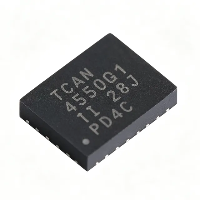
TCAN4550RGYRQ1 - CAN FD SBC with Transceiver 8Mbps VQFN-20 | TI
Teilenummer: TCAN4550RGYRQ1 ✓ Aktiv| Menge | Stückpreis | Gesamt |
|---|---|---|
| 1 | $5.2 | $5,20 |
| 10 | $4.68 | $46,80 |
| 100 | $4.15 | $415,00 |
| 500 | $3.55 | $1.775,00 |
| 1.000 | $3.1 | $3.100,00 |
TCAN4550RGYRQ1 Übersicht
A CAN FD (Controller Area Network Flexible Data Rate) system basis chip is an integrated mixed-signal IC that combines the ISO 11898-1 data link layer controller, the ISO 11898-2 physical layer transceiver, and an internal logic LDO into a single package. The CAN FD protocol extends classic CAN by allowing a higher data payload and a flexible bit rate, enabling automotive networks to scale from 1 Mbps to 8 Mbps while preserving the deterministic arbitration of classic CAN. Integrating the controller and the transceiver on one die reduces PCB area, removes the high-speed digital signals between two separate ICs, and improves EMC robustness versus discrete controller-plus-transceiver implementations.
Key specifications of the TCAN4550RGYRQ1 include CAN FD data rates up to 8 Mbps, ISO 11898-2:2016 physical layer compliance, an SPI host interface up to 10 MHz, integrated 5V/3.3V selectable LDO for VCC logic supply, low-power standby and sleep modes, and a watchdog timer. The 20-pin VQFN package with exposed thermal pad supports automotive power profiles while staying within a 3.5 x 4.5 mm footprint suitable for space-constrained ECUs.
The TCAN4550-Q1 uses a high-speed CAN transceiver with explicit bus-fault protection, thermal shutdown, and wide common-mode range for reliable communication on 12V automotive bus networks. The on-chip LDO generates the logic supply from the 5V CAN rail, removing the need for an external regulator in many applications. SPI registers expose CAN ID filters, bit-timing parameters (sample point and propagation delay), and diagnostic counters, which simplifies firmware bring-up.
Typical applications include automotive body control modules, gateways, battery management systems (BMS), powertrain ECUs, ADAS sensor nodes, and industrial CAN FD networks. The 8 Mbps capability is particularly valuable for high-throughput diagnostics and emerging zonal architectures in modern vehicles.
Designers should connect the exposed pad to a solid ground plane for thermal dissipation, place 100 nF + 1uF decoupling close to VCC and VIO pins, and follow ISO 11898-2 bus-termination guidance (60 ohm / 120 ohm) on the CANH/CANL differential pair. Verify SPI mode 0 timing against microcontroller datasheet before enabling CAN bus activity. This page synthesizes distributor pricing, drop-in alternatives, and design considerations not consolidated in the manufacturer datasheet.
Drop-in-Alternativen für TCAN4550RGYRQ1 – gleiches Gehäuse, Pin-kompatibel. Bauteile mit anderem Gehäuse, die eine PCB-Überarbeitung erfordern, sind ausgeschlossen.
Varianten dieser Serie
Modelle derselben Serie, die drop-in-kompatibel sind mit TCAN4550RGYRQ1 (gleiche Bauform und Footprint) – abweichend in Package, Protocol, Number of Drivers/Receivers, RoHS Status, Automotive Qualification.
Schnellvergleichstool – Wählen Sie Alternativbauteile für den Direktvergleich:
TCAN4550RGYR
✅ Drop-In📋 Referenzalternative (nicht im Katalog)
TCAN4550RGYTQ1
✅ Drop-In📋 Referenzalternative (nicht im Katalog)
TCAN1044DRQ1
✅ Drop-In ⚠️ Spezifikationen ungeprüft✓ Auf Lager
$0.62 / Stück
Datenblatt ansehen →TCAN1051-Q1
✅ Drop-In✓ Auf Lager
$1.05 / Stück
Datenblatt ansehen →TCAN1051DRBRQ1
✅ Drop-In✓ Auf Lager
$1.18 / Stück
Datenblatt ansehen →TCAN4550RGYRQ1 Grenzwerte & elektrische Eigenschaften
| Product Type | Automotive System Basis Chip (SBC) with CAN FD Controller and Transceiver |
| Data Protocol | CAN FD (ISO 11898-1:2015) / CAN 2.0B |
| Physical Layer Compliance | ISO 11898-2:2016 high-speed CAN |
| Maximum Data Rate | 8 Mbps |
| Logic Supply (VIO) | 1.8V / 3.3V / 5V selectable |
| Host Interface | SPI up to 10 MHz, mode 0/1 |
| Integrated LDO | Yes (5V or 3.3V selectable output) |
| Low-Power Modes | Standby and Sleep |
| Watchdog Timer | Yes (SPI-driven window watchdog) |
| Betriebstemperatur | -40C to +125C |
| Gehäuse | 20-pin VQFN (RGY) 3.5 x 4.5 mm with exposed pad |
| Automotive Qualification | AEC-Q100 Grade 1 |
| Montageart | Surface Mount |
| RoHS-Status | Compliant |
| Number of Channels | 1 CAN FD channel |
| Common-Mode Range | -12V to +12V (CAN bus) |
TCAN4550RGYRQ1 Pin-Konfiguration
| Pin 1 | VBAT — Battery / supply voltage input (typically 5V-18V from automotive bus) |
| Pin 2 | VCC — 5V regulator output / CAN transceiver supply |
| Pin 3 | GND — Ground |
| Pin 4 | CANH — CAN high-side differential bus line |
| Pin 5 | CANL — CAN low-side differential bus line |
| Pin 6 | INH — Inhibit / wake output (high when active) |
| Pin 7 | WAKE — Wake-up input from bus |
| Pin 8 | RSTn — Reset input (active low) |
| Pin 9 | CSn — SPI chip select (active low) |
| Pin 10 | SCLK — SPI clock input |
| Pin 11 | SDI — SPI data in (MOSI) |
| Pin 12 | SDO — SPI data out (MISO) |
| Pin 13 | INTn — Interrupt output to MCU (active low) |
| Pin 14 | GPIO1 — General purpose IO / wake source |
| Pin 15 | GPIO2 — General purpose IO |
| Pin 16 | VIO — Host-side logic supply (1.8V / 3.3V / 5V) |
| Pin 17 | VDD — Internal digital core supply |
| Pin 18 | NC — Not connected (per datasheet) |
| Pin 19 | NC — Not connected (per datasheet) |
| Pin 20 | NC — Not connected (per datasheet) |
| Pin EP | GND Pad — Exposed thermal pad - must be soldered to ground plane |
Typische Anwendungen
TCAN4550RGYRQ1 ist geeignet für 7 Anwendungs: Automotive Body Control Module (BCM), Automotive Gateway ECU, Battery Management System (BMS) for EV, ADAS Sensor Nodes (Radar/Lidar), Industrial CAN FD Networks (Modbus/IoT), Powertrain / Engine Control ECU, Charger and DC-DC Converter Modules.
Automotive Body Control Module (BCM)
The TCAN4550RGYRQ1's 8 Mbps CAN FD support, -40C to +125C operation, and AEC-Q100 qualification make it a strong fit for body control modules driving lighting, seat, mirror, and door-zone ECUs. Compared to classic CAN at 1 Mbps, FD tripling the payload reduces bus load by 60% on multi-zone BCMs. The SPI host interface streams 50+ messages per second to the body MCU without burdening the SPI bus. The integrated LDO removes the external 3.3V regulator that discrete transceiver stacks typically require for the host-side logic rail, saving BOM and PCB area.
Empfohlen
Automotive Gateway ECU
In zonal or central gateway ECUs, the TCAN4550RGYRQ1's 8 Mbps capability lets it aggregate 4-8 CAN FD channels from sub-networks and forward high-throughput diagnostic traffic to the central compute. The integrated LDO and watchdog timer reduce external component count in the gateway, which typically hosts 4-12 SBCs. AEC-Q100 Grade 1 supports underhood gateway placement where ambient temperatures exceed 85C. Use multiple TCAN4550RGYRQ1 devices in parallel for redundant gateways with deterministic SPI control.
Empfohlen
Battery Management System (BMS) for EV
The TCAN4550RGYRQ1 serves BMS master and cell-monitoring modules in 400V and 800V EV battery packs, where CAN FD's 8 Mbps accelerates cell-balancing data upload to the pack controller. The integrated transceiver's -12V to +12V common-mode range survives ground-shift transients from 200A+ battery currents during pre-charge. AEC-Q100 Grade 1 tolerates underpack temperatures of 105C. The integrated 5V LDO can power external cell-monitor ICs, eliminating one regulator in the BOM.
Empfohlen
ADAS Sensor Nodes (Radar/Lidar)
ADAS radar and lidar ECUs use the TCAN4550RGYRQ1's 8 Mbps CAN FD to push high-bandwidth object-list data upstream to the fusion ECU in real time. The SPI host interface lets the radar MCU run free of CAN interrupt overhead. AEC-Q100 Grade 1 handles thermal load in windshield-mounted or bumper-mounted sensor pods. Integrated LDO simplifies the power tree where PCB area is constrained to 25 x 35 mm.
Empfohlen
Industrial CAN FD Networks (Modbus/IoT)
Industrial CANopen and CANopen FD nodes use the TCAN4550RGYRQ1 (or the non-automotive TCAN4550RGYR variant) for PLC-to-remote-IO communication. The 8 Mbps CAN FD dramatically reduces scan time on multi-axis motion-control networks versus classic CAN at 1 Mbps. The integrated LDO handles 24V industrial input via an upstream switching regulator. The SPI host interface allows simple microcontroller arbitration across multi-vendor industrial networks.
Empfohlen
Powertrain / Engine Control ECU
Powertrain ECUs leverage the TCAN4550RGYRQ1's 8 Mbps CAN FD for diagnostics, calibration, and OBD-III communications on gasoline and diesel platforms. The AEC-Q100 Grade 1 (-40C to +125C) rating sustains underhood ambient at 110C+ with engine-on duty cycles. The integrated LDO simplifies harsh-environment power design. Lower bit-rate operation (500 kbps) remains supported, so existing classic-CAN calibration tools do not require firmware updates.
Empfohlen
Charger and DC-DC Converter Modules
Onboard EV chargers and DC-DC converters use the TCAN4550RGYRQ1 to communicate charging status, fault flags, and high-voltage telemetry over CAN FD to the vehicle master. The integrated LDO removes an external regulator in the high-voltage isolation boundary. The exposed pad of the 20-pin VQFN package supports sustained operation at 1W bus-load in the charger enclosure. The wide common-mode range tolerates chassis-ground shift on 800V architectures.
Empfohlen
Zusammenfassung der empfohlenen Produkte
Technische Referenzdaten für TCAN4550RGYRQ1 – Vergleich, Designhinweise und Compliance-Informationen.
Auswahlhilfe
Vergleich mit Alternativen
| Parameter | Dieses Produkt | TCAN4550RGYR | TCAN4550RGYTQ1 | TCAN1044DRQ1 | TCAN1051-Q1 | TCAN1051DRBRQ1 |
|---|---|---|---|---|---|---|
| Brand | Texas Instruments | Texas Instruments | Texas Instruments | Texas Instruments | Texas Instruments | Texas Instruments |
| Package | VQFN-20 (RGY) 3.5x4.5 mm | VQFN-20 (RGY) - same | VQFN-20 (RGY) - same | VQFN-20 family | VQFN-20 family | VQFN-20 family |
| Function | Controller + Transceiver + LDO (SBC) | Controller + Transceiver + LDO (SBC) | Controller + Transceiver + LDO (SBC) | Transceiver only | Transceiver only | Transceiver only |
| CAN FD Data Rate | 8 Mbps | 8 Mbps | 8 Mbps | 8 Mbps | 5 Mbps | 5 Mbps |
| AEC-Q100 | Grade 1 | Not qualified (industrial) | Grade 1 | Grade 1 | Grade 1 | Grade 1 |
| Integrated LDO | Yes (5V/3.3V selectable) | Yes (5V/3.3V selectable) | Yes (5V/3.3V selectable) | No (transceiver only) | No (transceiver only) | No (transceiver only) |
| Host Interface | SPI (up to 10 MHz) | SPI (up to 10 MHz) | SPI (up to 10 MHz) | N/A (transceiver) | N/A (transceiver) | N/A (transceiver) |
| Operating Temperature | -40C to +125C | -40C to +125C | -40C to +125C | -40C to +150C | -40C to +125C | -40C to +125C |
| Unit Price (1pc, as of 2026-10-10) | $5.20 | $4.85 | $5.20 | $1.65 | $1.95 | $1.85 |
Wichtigste Unterscheidungsmerkmale
- Single-chip Controller + Transceiver + LDO integration (vs. TCAN1051DRBRQ1 (transceiver only))
- 8 Mbps CAN FD support (vs. TCAN1051-Q1 (5 Mbps))
- AEC-Q100 Grade 1 across full temperature range (vs. TCAN4550RGYR (industrial))
Designhinweise
The 20-pin VQFN (RGY) package dissipates heat through the exposed pad (EP pin). Solder the EP directly to a continuous ground plane of at least 1 oz copper covering 100 mm^2. Estimated: at 8 Mbps full-duplex operation the part draws roughly 50 mA worst case from VCC, requiring 250 mW dissipation at typical automotive 12V VIN. Keep CANH/CANL traces short (<100 mm) to minimize high-current driver stress and avoid coupling across the EP pad.
Place 100 nF ceramic + 1 uF bulk decoupling capacitors within 3 mm of the VCC and VIO pins. Split the analog and digital grounds with a star-connection back at the device EP. Maintain 0.1 inch CANH/CANL bus trace spacing for 120 ohm differential impedance. Avoid running the SPI traces parallel to the CAN bus traces to prevent 8 Mbps CAN edge coupling into the SPI clock. Reference: TI TCAN4550-Q1 datasheet layout section.
Do not enable the CAN controller until SPI mode 0/1 timing is verified against the host MCU's SPI clock - mis-clocked SDI/SDO causes silent fault flags that lock the CAN state machine. Do not omit the 60 ohm / 120 ohm termination resistors on the bus end-nodes, even in bench setups (use split termination with 4.7 nF caps for high-EMC environments). Avoid latching in sleep mode without verifying wake source polarity; the INH pin state must match the host MCU's power-down sequence.
Compliance-Informationen
AEC-Q100 Grade 1 qualified per TI product page. RoHS and REACH compliant. Lead-free and halogen-free per ordering part decode.







