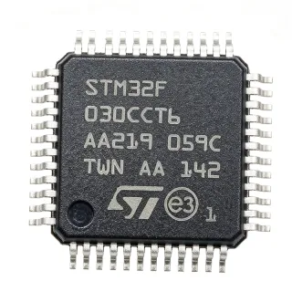
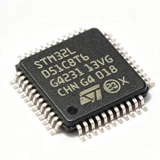
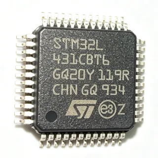
STM32F100C6T6B - 24MHz Cortex-M3 MCU 32KB LQFP-48 | STMicroelectronics
N.º de pieza: STM32F100C6T6B ✓ Activo| Cant. | Precio unitario | Total |
|---|---|---|
| 1 | $3.85 | $3,85 |
| 10 | $3.42 | $34,20 |
| 100 | $2.74 | $274,00 |
| 500 | $2.31 | $1.155,00 |
| 1.000 | $1.96 | $1.960,00 |
| 2.500 | $1.62 | $4.050,00 |
STM32F100C6T6B Descripción general
A microcontroller (MCU) is a single-chip computer containing a processor core, program memory (Flash), working memory (SRAM), and a rich peripheral mix including timers, ADCs, communication interfaces, and GPIO. Within the broader category hierarchy, the STM32F100 sits at Microcontroller -> ARM Cortex-M MCU -> 32-bit MCU -> Embedded Processor -> Semiconductor. Cortex-M3 cores implement the ARMv7-M architecture with Thumb-2 instruction set, deterministic interrupt handling, and hardware division — making them well suited to real-time control tasks.
Key features of the STM32F100C6T6B include a 12-bit ADC (1 µs conversion), two 12-bit DACs, six general-purpose 16-bit timers, a 24 MHz maximum core clock, and up to 37 GPIO pins. The device integrates up to eight communication interfaces including I2C, SPI, USART, and CAN, plus a 1-channel advanced timer for motor control. Operating voltage spans 2.0 V to 3.6 V across the –40 °C to +85 °C industrial temperature range.
Architecturally, the part uses ST's 130 nm CMOS process with embedded Flash and a nested vector interrupt controller (NVIC) capable of handling up to 60 maskable interrupt sources. The integrated voltage regulator supports both run, sleep, stop, and standby low-power modes. Hardware CRC and 96-bit unique device ID reduce firmware overhead and enable secure identification.
Typical applications include home appliances and white goods, HVAC control, motor control for low-voltage DC and stepper motors, industrial sensors, USB accessories, and low-cost consumer electronics such as remote controls, toys, and LED lighting controllers. The wide peripheral mix also makes the STM32F100C6T6B suitable for smart-metering peripherals and simple HMI boards.
When designing with this part, note that the 48-pin LQFP footprint is shared across much of the STM32F1 family, allowing straightforward migration to higher-density parts (C8/CB) without PCB redesign. Ensure the BOOT0 strap and NRST reset network follow ST's reference design, and respect the 3.3 V supply tolerance for reliable Flash operation.
This page synthesizes distributor pricing, drop-in LQFP-48 alternatives, and practical design notes not found in the standalone manufacturer datasheet.
Alternativas directas para STM32F100C6T6B — mismo encapsulado, compatible pin a pin. Se excluyen las piezas de otro encapsulado que requieren retrabajo de la PCB.
Variantes de esta serie
Modelos de la misma serie compatibles directamente con STM32F100C6T6B (mismo factor de forma y huella) — difiere en Flash Memory, Package, SRAM, Timers.
Herramienta de comparación rápida — seleccione piezas alternativas para compararlas lado a lado:
STM32F100C8T6B
✅ Sustitución directa📋 Alternativa de referencia (no en el catálogo)
STM32F100CBT6B
✅ Sustitución directa📋 Alternativa de referencia (no en el catálogo)
STM32F101C6T6A
✅ Sustitución directa ⚠️ Especificaciones sin verificar📋 Alternativa de referencia (no en el catálogo)
STM32F102C6T6
✅ Sustitución directa ⚠️ Especificaciones sin verificar📋 Alternativa de referencia (no en el catálogo)
STM32F103C6T6
✅ Sustitución directa ⚠️ Especificaciones sin verificar✓ En stock
$2.05 / unidad
Ver hoja de datos →STM32F100C6T6B Valores máximos y características eléctricas
| Core | ARM Cortex-M3 32-bit RISC |
| Frecuencia de reloj máxima | 24 MHz |
| Flash Memory | 32 KB |
| SRAM | 4 KB |
| Operating Voltage | 2.0 V to 3.6 V |
| Encapsulado | LQFP-48 (7x7 mm) |
| Recuento de pines | 48 |
| Tipo de montaje | Surface Mount |
| Temperatura de funcionamiento | -40 C to +85 C |
| GPIO Count | Up to 37 |
| ADC | 1x 12-bit, up to 10 channels (1 us conversion) |
| DAC | 2x 12-bit |
| Timers | 6x general-purpose 16-bit, 1x advanced-control (PWM) |
| Communication Interfaces | Up to 8 (I2C, SPI, USART, CAN) |
| Nivel MSL | 3 (168 hours) |
| Estado RoHS | Compliant |
Configuración de pines de STM32F100C6T6B
| Pin 1 | VBAT — Battery input for RTC domain |
| Pin 2 | PC13 — GPIO/Tamper-RTC |
| Pin 3 | PC14 — GPIO/OSC32_IN |
| Pin 4 | PC15 — GPIO/OSC32_OUT |
| Pin 5 | OSC_IN — External clock input |
| Pin 6 | OSC_OUT — External clock output |
| Pin 7 | NRST — Reset (active-low) |
| Pin 8 | VSSA — Analog ground |
| Pin 9 | VDDA — Analog supply |
| Pin 10 | PA0 — GPIO/ADC_IN0/WKUP |
| Pin 11 | PA1 — GPIO/ADC_IN1 |
| Pin 12 | PA2 — GPIO/USART2_TX |
| Pin 13 | PA3 — GPIO/USART2_RX |
| Pin 14 | PA4 — GPIO/SPI1_NSS/DAC12 |
| Pin 15 | PA5 — GPIO/SPI1_SCK/DAC1 |
| Pin 16 | PA6 — GPIO/SPI1_MISO/ADC_IN6 |
| Pin 17 | PA7 — GPIO/SPI1_MOSI/ADC_IN7 |
| Pin 18 | PB0 — GPIO/ADC_IN8 |
| Pin 19 | PB1 — GPIO/ADC_IN9 |
| Pin 20 | PB2 — GPIO/BOOT1 |
| Pin 21 | PB10 — GPIO/I2C2_SCL/USART3_TX |
| Pin 22 | PB11 — GPIO/I2C2_SDA/USART3_RX |
| Pin 23 | VSS_1 — Digital ground |
| Pin 24 | VDD_1 — Digital supply |
| Pin 25 | PB12 — GPIO/SPI2_NSS |
| Pin 26 | PB13 — GPIO/SPI2_SCK |
| Pin 27 | PB14 — GPIO/SPI2_MISO |
| Pin 28 | PB15 — GPIO/SPI2_MOSI |
| Pin 29 | PA8 — GPIO/TIM1_CH1 |
| Pin 30 | PA9 — GPIO/USART1_TX/TIM1_CH2 |
| Pin 31 | PA10 — GPIO/USART1_RX/TIM1_CH3 |
| Pin 32 | PA11 — GPIO/USART1_CTS/TIM1_CH4 |
| Pin 33 | PA12 — GPIO/USART1_RTS |
| Pin 34 | PA13 — GPIO/SWDIO |
| Pin 35 | VSS_2 — Digital ground |
| Pin 36 | VDD_2 — Digital supply |
| Pin 37 | PA14 — GPIO/SWCLK |
| Pin 38 | PA15 — GPIO/SPI3_NSS |
| Pin 39 | PB3 — GPIO/SPI3_SCK |
| Pin 40 | PB4 — GPIO/SPI3_MISO |
| Pin 41 | PB5 — GPIO/SPI3_MOSI |
| Pin 42 | PB6 — GPIO/I2C1_SCL |
| Pin 43 | PB7 — GPIO/I2C1_SDA |
| Pin 44 | BOOT0 — Boot mode select |
| Pin 45 | PB8 — GPIO/TIM4_CH1 |
| Pin 46 | PB9 — GPIO/TIM4_CH2 |
| Pin 47 | VSS_3 — Digital ground |
| Pin 48 | VDD_3 — Digital supply |
Aplicaciones típicas
STM32F100C6T6B es adecuado para 7 aplicacións: Home Appliance Control, HVAC Fan and Blower Control, Industrial Sensor Nodes, Low-Cost LED Lighting Controllers, USB Accessories (via F101 and similar), Smart Metering Peripherals, Toys and Consumer Electronics.
Home Appliance Control
The STM32F100C6T6B's 24 MHz Cortex-M3 core, 12-bit ADC, and 16-bit advanced-control timer TIM1 suit washing machines, microwave ovens, and induction cooktops. The 48-pin LQFP exposes enough GPIO for keypad scanning, triac control, and LED status, while the 32 KB Flash holds motor-state and user-interface firmware. Six 16-bit timers drive PWM outputs at the 24 MHz core rate, adequate for low-frequency triac-based heater regulation; this 24 MHz bandwidth is exactly why ST positioned the F100 as the value-line for white goods.
Recomendado
HVAC Fan and Blower Control
BLDC and brushed-DC fans require closed-loop PWM control with back-EMF sensing; the STM32F100C6T6B's TIM1 advanced-control timer provides complementary PWM with dead-time insertion and a 1 µs ADC for current feedback. The 32 KB Flash holds PI/PID firmware and lookup tables, while 4 KB SRAM is enough for sensor fusion. Compared with the F103, the F100's 24 MHz clock trades DSP headroom for lower BOM cost; this part wins when the controller loops below 10 kHz.
Recomendado
Industrial Sensor Nodes
Industrial 4-20 mA loop-powered sensors benefit from the STM32F100C6T6B's 2.0-3.6 V wide supply and –40 °C to +85 °C industrial temperature range. The Cortex-M3 core handles Modbus RTU framing over USART, while 32 KB Flash stores calibration coefficients and 4 KB SRAM buffers samples. The 12-bit ADC and DAC combination enables analog sensor trimming in the field. The 24 MHz core is intentionally down-clocked vs the F103 to save quiescent current for loop-powered designs.
Recomendado
Low-Cost LED Lighting Controllers
DMX-512 and DALI LED drivers use the STM32F100C6T6B's USART for protocol framing and TIM1 PWM for smooth dimming. The 12-bit DAC sets constant-current references for analog dimming fallback. With 32 KB Flash, the firmware fits DMX/DALI stacks plus color-temperature curves. This part's lower 24 MHz ceiling is rarely a limitation for lighting loops, and the F100 value-line pricing keeps 4-channel RGBW fixtures under BOM targets.
Recomendado
USB Accessories (via F101 and similar)
Although the STM32F100C6T6B itself lacks USB, the value-line family is commonly deployed alongside USB-serial bridges. The 48-pin LQFP exposes the USARTs needed for CDC-class bridges and the timers for HID-class button reporting. STM32F102 (USB-found 48 pin variant) shares the same footprint and is often co-deployed. The F100 remains attractive as a slave processor that offloads USB stacks from the host MCU; firmware migration to STM32F102 is one register change.
Recomendado
Smart Metering Peripherals
Electricity, gas, and heat meters use the STM32F100C6T6B's 12-bit ADC for voltage and current sensing plus the integrated RTC for time-stamping. The 4 KB SRAM buffers interval data while 32 KB Flash stores tariff tables. ST's value-line positioning targets sub-2-USD BOMs at qty 1k, a key cost target for utility-grade meters. The 24 MHz core is adequate for IEC 62056-21 protocol stacks and 100 Hz sample rates on metrology ADCs.
Recomendado
Toys and Consumer Electronics
Battery-powered toys, remote-controlled devices, and educational electronics use the STM32F100C6T6B for its low active current at 24 MHz and rich timer set. Six 16-bit timers drive servo, motor, and audio PWM channels; 4 KB SRAM holds small audio buffers; and 32 KB Flash fits simple games and UI flows. The 2.0 V minimum supply allows direct Li-Ion or 2x AA operation, simplifying battery use cases where a single-cell Li-Ion or 2x AA pack is the source.
Recomendado
Resumen de productos recomendados
Datos de referencia de ingeniería para STM32F100C6T6B — comparación, orientación de diseño e información de cumplimiento.
Guía de selección
Comparación con alternativas
| Parámetro | Este producto | STM32F100C8T6B | STM32F100CBT6B | STM32F101C6T6A | STM32F102C6T6 | STM32F103C6T6 |
|---|---|---|---|---|---|---|
| Brand | STMicroelectronics | STMicroelectronics | STMicroelectronics | STMicroelectronics | STMicroelectronics | STMicroelectronics |
| Package | LQFP-48 (7x7 mm) | LQFP-48 (7x7 mm) - same | LQFP-48 (7x7 mm) - same | LQFP-48 (7x7 mm) - same | LQFP-48 (7x7 mm) - same | LQFP-48 (7x7 mm) - same |
| Core | ARM Cortex-M3 | ARM Cortex-M3 | ARM Cortex-M3 | ARM Cortex-M3 | ARM Cortex-M3 | ARM Cortex-M3 |
| Maximum Clock | 24 MHz | 24 MHz - same | 24 MHz - same | 36 MHz - +50% | 48 MHz - +100% | 72 MHz - +200% |
| Flash Memory | 32 KB | 64 KB - +100% | 128 KB - +300% | 32 KB - same | 32 KB - same | 32 KB - same |
| SRAM | 4 KB | 8 KB - +100% | 8 KB - +100% | 6 KB - +50% | 4 KB - same | 10 KB - +150% |
| USB | No | No | No | No | USB FS - added | USB FS - added |
| CAN | Yes (bxCAN) | Yes - same | Yes - same | Yes - same | No - removed | Yes - same |
Diferenciadores clave
- Lowest-cost STM32F1 LQFP-48 with Cortex-M3 at 24 MHz (frente a STM32F103C6T6)
- Migration path to 64 KB and 128 KB Flash on same footprint (frente a GD32F130C6T6 (cross-brand))
- Higher-density STM32F102 migration adds integrated USB (frente a STM32F103C6T6)
Notas de diseño
The STM32F100C6T6B integrates a 1.8 V LDO regulator from the 2.0-3.6 V VDD supply. Decouple each VDD pin (1, 24, 36, 48) with a 100 nF ceramic capacitor placed within 5 mm of the pin, and add a bulk 4.7 uF tantalum or ceramic on the main 3.3 V rail. VDDA must be tied to VDD with an LC filter (10 ohm + 100 nF) to keep ADC noise below 1 LSB; VSSA ties directly to the ground plane.
BOOT0 must be tied to ground through a 10 kohm resistor for normal Flash execution; leaving it floating causes intermittent boot failures when noise couples to the pin. The NRST line needs a 10 kohm pull-up and a 100 nF capacitor to VSS for proper reset - omitting these causes brown-out instability. For SWD debugging, expose PA13 (SWDIO) and PA14 (SWCLK) on the PCB even if not populated, so future debug access is possible without board rework.
Route the crystal traces (OSC_IN/OSC_OUT) as short as possible, symmetric in length, and guard-trace with a ground pour. Place the load capacitors (typically 15 pF for 8 MHz HSE) within 2-3 mm of the pins. The 48-pin LQFP has 0.5 mm pitch, which is hand-solderable with a fine tip but requires a reflow profile per JEDEC J-STD-020 (peak 245 C for SnAgCu). Use at least 6 ground pins as thermal vias to a continuous ground plane for STM32 thermal performance.
The STM32F100C6T6B's GPIO toggles at speeds up to 18 MHz; for SPI signals above 9 MHz, add 33 ohm series damping resistors near the MCU to suppress reflections on traces longer than 25 mm. Keep analog ADC inputs (PA0-PA7, PB0-PB1) physically separated from switching signals (PWM outputs on PA8-PA12) on different ground islands joined at the MCU's VSSA pin to avoid digital switching noise coupling into ADC measurements.
Información de cumplimiento
RoHS compliant per ST product page. Not AEC-Q100 qualified - choose STM32F100 automotive-grade variant (R6T6B) for automotive use.