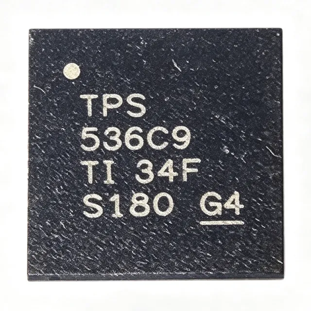
TPS536C9RSLR - Dual-Channel 12-Phase D-CAP+ Controller | TI
N.º de pieza: TPS536C9RSLR ✓ Activo| Cant. | Precio unitario | Total |
|---|---|---|
| 1 | $24.5455 | $24,55 |
| 10 | $17.7273 | $177,27 |
| 100 | $15.6818 | $1.568,18 |
| 500 | $15 | $7.500,00 |
| 1.000 | $14.3182 | $14.318,20 |
TPS536C9RSLR Descripción general
A multiphase buck controller is a switching-voltage-regulator controller that interleaves multiple power stages, sharing current across phases to distribute thermal load, reduce input and output ripple, and enable very fast transient response. Multiphase controllers sit at the top of the power management hierarchy, orchestrating NexFET power stages that each integrate driver and FET functions.
Key features include the D-CAP+ control architecture with undershoot reduction (USR) and overshoot reduction (OSR) for fast transient response with low output capacitance; built-in non-volatile memory (NVM) for configuration storage; full PMBus command support for telemetry and control; and Intel VR14 SVID compliance for direct communication with Intel processors. The two channels (N + M) can be flexibly phase-assigned up to 12 total phases, supporting dual-rail designs such as VCORE plus VSOC.
The device is fully compatible with TI NexFET power stages (such as the CSD and TPS power-stage families), enabling a complete controller-plus-power-stage solution with differential remote voltage sensing and per-phase current balance. Digital loop control provides programmable transient behavior and startup sequencing without external compensation components.
Typical applications include Intel server CPU core rails (VR14), AI accelerator and GPU core power, high-current ASIC and FPGA point-of-load conversion, and storage or networking processor supplies.
Design consideration: the controller requires configuration via NVM programming (TI Fusion Digital Power Designer) and careful layout of the differential remote sense lines and current-sense routing to the power stages; follow the TI datasheet layout guidelines for SW, VOSNS, and CS pins to achieve specified transient accuracy.
Alternativas directas para TPS536C9RSLR — mismo encapsulado, compatible pin a pin. Se excluyen las piezas de otro encapsulado que requieren retrabajo de la PCB.
Variantes de esta serie
Modelos de la misma serie compatibles directamente con TPS536C9RSLR (mismo factor de forma y huella) — difiere en Non-Volatile Memory, Package, Topology, Control Interface, Number of Channels.
Herramienta de comparación rápida — seleccione piezas alternativas para compararlas lado a lado:
TPS53622RSBT
✓ En stock
$3.96 / unidad
Ver hoja de datos →TPS53624
✓ En stock
$1.86 / unidad
Ver hoja de datos →TPS53679RSBR
📋 Alternativa de referencia (no en el catálogo)
TPS53681RSBR
📋 Alternativa de referencia (no en el catálogo)
NCP81174
📋 Alternativa de referencia (no en el catálogo)
TPS536C9RSLR Valores máximos y características eléctricas
| Topología | Step-down multiphase buck controller |
| Control Architecture | D-CAP+ with USR and OSR |
| Number of Channels | 2 |
| Total Phase Count | Up to 12 (N + M <= 12) |
| Interfaces | PMBus, Intel VR14 SVID |
| Target Application Standard | Intel VR14 |
| Non-Volatile Memory | Yes (integrated NVM) |
| Power Stage Compatibility | TI NexFET power stages |
| Encapsulado | 48-VQFN (RSL), 6x6 mm |
| Temperatura de funcionamiento | -40C to +125C |
| Tipo de montaje | Surface Mount |
| Current Sharing | Multiphase current balance |
| Remote Sensing | Differential remote voltage sense |
| Transient Features | Undershoot reduction (USR), overshoot reduction (OSR) |
| Application | Intel VR14 CPU voltage regulator |
| Estado RoHS | Compliant |
Guía de configuración de pines de TPS536C9RSLR 48-vqfn (rsl), 6x6 mm
Configuración de pines para TPS536C9RSLR (encapsulado 48-vqfn (rsl), 6x6 mm). Este dispositivo de potencia presenta terminales de puerta, drenador y fuente. Para encapsulados no polarizados, consulte la hoja de datos del fabricante para conocer la orientación exacta del pin 1 y los detalles del footprint. Las aplicaciones habituales incluyen el diseño de fuentes de alimentación, el accionamiento de motores y la conmutación de cargas.

No hay datos detallados de patillaje disponibles para TPS536C9RSLR.
Consulte la hoja de datos para ver la configuración completa de patillas.
Aplicaciones típicas
TPS536C9RSLR es adecuado para 6 aplicacións: Intel Server CPU Core Power (VR14), AI Accelerator and GPU Power, Datacenter Storage and Networking Processor Rails, High-Performance FPGA and ASIC Point-of-Load, Test and Measurement Instrument Power, Industrial Edge Computing Servers.
Intel Server CPU Core Power (VR14)
The TPS536C9RSLR is purpose-built for Intel VR14 server CPU core voltage regulation. Its VR14 SVID interface communicates directly with the processor for dynamic voltage and frequency scaling, while the N + M <= 12 phase allocation covers multi-core VCORE demands with fast transient response. The D-CAP+ architecture with USR and OSR limits excursions during heavy load steps, allowing lower output capacitance and reduced BOM cost per server board.
Recomendado
AI Accelerator and GPU Power
AI training and inference cards require hundreds of amps delivered to processor cores with tight regulation. The TPS536C9RSLR supports up to 12 interleaved phases across two channels, distributing heat across NexFET power stages and reducing ripple per phase. PMBus telemetry allows the host to monitor voltage, current, and temperature in real time, which is valuable for fleet-level health management in datacenter GPU deployments.
Recomendado
Datacenter Storage and Networking Processor Rails
Network processors and storage controllers in servers need dual high-current rails with sequencing and monitoring. The TPS536C9RSLR provides two independently configurable channels with NVM-programmed startup sequencing and PMBus control, letting one controller manage both rails and reduce controller count. Its -40C to +125C rating covers the elevated ambient temperatures found in dense switch and storage chassis.
Recomendado
High-Performance FPGA and ASIC Point-of-Load
FPGAs and ASICs often require a large-core rail plus a secondary rail, exactly matching the TPS536C9RSLR dual-channel structure. Differential remote sensing compensates for PCB voltage drop at high current, and the digital loop allows engineers to tune transient response in firmware when load profiles change late in a project. Compatibility with TI NexFET power stages shortens the design cycle for custom accelerator boards.
Recomendado
Test and Measurement Instrument Power
High-end instrumentation processors share the same VR14-style core power requirements as servers. The TPS536C9RSLR offers deterministic transient behavior via USR/OSR control, which helps maintain stable core voltage during sharp computational load bursts in real-time signal processing. PMBus telemetry also enables instrument self-diagnostics, reporting rail health to the system controller for predictive maintenance.
Recomendado
Industrial Edge Computing Servers
Edge servers deployed in factories run the same Intel processors as datacenter units but face wider ambient temperatures. The TPS536C9RSLR industrial rating of -40C to +125C, RoHS-compliant VQFN-48 package, and PMBus configurability make it suitable for ruggedized edge compute nodes. NVM-based configuration survives power cycles without host intervention, simplifying deployments in unattended environments.
Recomendado
Resumen de productos recomendados
Datos de referencia de ingeniería para TPS536C9RSLR — comparación, orientación de diseño e información de cumplimiento.
Guía de selección
Comparación con alternativas
| Parámetro | Este producto | TPS53622RSBT | TPS53679RSBR | NCP81174 |
|---|---|---|---|---|
| Brand | Texas Instruments | Texas Instruments | Texas Instruments | onsemi |
| VR Interface | Intel VR14 SVID | Legacy VR (VR13-era) | VR13/VR13.HC | VR14-class |
Diferenciadores clave
- Intel VR14 SVID compliance (frente a TPS53622RSBT)
- USR/OSR transient reduction (frente a TPS53679RSBR)
- Integrated NVM configuration (frente a NCP81174)
Notas de diseño
Follow TI datasheet layout guidelines for the VOSNS differential remote sense pair, per-phase current-sense (CS) routing, and SW node routing to the NexFET power stages. Route remote sense lines as a Kelvin pair away from switching nodes to avoid offset errors; at high current, even a few milliohms of PCB trace causes significant load-line error. Place the controller centrally among power stages to equalize phase signal routing lengths.
Configure phase assignment (N + M <= 12) via NVM before power-up testing. Balance per-phase current by matching power stage RDS(on) sense paths and inductor DCR tolerance; mismatched phases cause thermal hotspots and reduced transient performance. Use the USR/OSR features to trade output capacitance against transient undershoot rather than over-provisioning bulk caps.
The TPS536C9 must match the processor VR interface version: it is VR14 SVID compliant and is not backward compatible with VR13 SVID protocols. Verify the target CPU VR specification before layout. Also remember NVM programming via TI Fusion Digital Power Designer is a required production step; an unprogrammed controller will not boot with your intended rail configuration.
Información de cumplimiento
RoHS-compliant per TI product listing. This is a server/industrial grade controller; AEC-Q100 automotive qualification is not claimed in the provided data.







