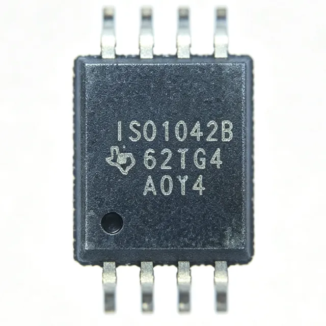
ISO1042BQDWVRQ1 - 5Mbps Isolated CAN FD Transceiver | TI
部品番号: ISO1042BQDWVRQ1 ✓ 生産中| 数量 | 単価 | 小計 |
|---|---|---|
| 1 | $2.41 | $2.41 |
| 10 | $2.17 | $21.70 |
| 100 | $1.86 | $186.00 |
| 500 | $1.68 | $840.00 |
| 1,000 | $1.5052 | $1,505.20 |
ISO1042BQDWVRQ1 概要
An isolated CAN transceiver is a signal interface IC that combines a CAN physical-layer transceiver with a digital isolator in a single package. In the system hierarchy, it sits between the host microcontroller or CAN controller (logic side) and the two-wire CAN bus (bus side), providing galvanic isolation that blocks ground loops, common-mode transients, and high-voltage faults - critical in vehicles and industrial networks where nodes span large distances and different ground domains.
Key features include support for CAN FD flexible data rates up to 5 Mbps, enabling much faster payload transfer than classic CAN's 500 kbps; a logic-side supply range down to 1.8 V for direct interfacing with low-voltage MCUs; and robust protection with ±70-V DC bus fault tolerance. The device meets the ISO11898-2 (2016) standard and integrates one driver and one receiver channel with typical operating supply current of about 43 mA.
The ISO1042-Q1 family uses TI capacitive isolation technology, providing a reliable galvanic barrier suited to automotive and industrial environments. The wide-body SOIC-8 (DWV) package provides substantial creepage and clearance distance across the isolation barrier, supporting basic and reinforced isolation ratings.
Typical applications include electric vehicle powertrain and battery management networks, body control modules, industrial PLC and motor drive CAN buses, and building automation nodes - anywhere CAN nodes must be isolated from ground potential differences or bus faults.
Design consideration: use split-termination or 120-ohm bus termination per ISO11898-2, and place 100-nF decoupling capacitors close to both VCC1 and VCC2 pins to maintain signal integrity at 5-Mbps CAN FD bit rates.
This page synthesizes distributor pricing, drop-in alternatives, comparison data, and practical design notes not found in the manufacturer datasheet alone.
ドロップイン代替品: ISO1042BQDWVRQ1 — 同一パッケージでピン互換。PCBの作り直しが必要な異なるパッケージの部品は除外されています。
このシリーズのバリエーション
同一シリーズでドロップイン互換のモデル: ISO1042BQDWVRQ1 (同一形状・フットプリント) — 相違点: Bus Fault Protection, Package, Product Type.
クイック比較ツール — 並列比較する代替部品を選択:
ISO1042BQDWVQ1
✅ ドロップイン📋 参考代替品(カタログ未掲載)
ISO1042QDWVQ1
✅ ドロップイン📋 参考代替品(カタログ未掲載)
ISO1042DWVR
✅ ドロップイン📋 参考代替品(カタログ未掲載)
ISO1050DWR
✅ ドロップイン📋 参考代替品(カタログ未掲載)
ISO1042BQDWVRQ1 仕様
| Product Type | Galvanically-isolated CAN FD transceiver |
| Standard Compliance | ISO11898-2 (2016) |
| Maximum Data Rate | 5 Mbps (CAN FD) |
| Bus Fault Protection | ±70 V DC |
| Common-Mode Voltage Range | ±30 V |
| Logic-Side Supply (VCC1) | 1.8 V to 5.5 V |
| Bus-Side Supply (VCC2) | 4.5 V to 5.5 V |
| Typical Operating Supply Current | 43 mA |
| Isolation Rating | Basic, Reinforced |
| Channels (Driver/Receiver) | 1/1 |
| Qualification | AEC-Q100 qualified |
| 動作温度 | -40C to +125C |
| パッケージ | 8-pin wide-body SOIC (DWV) |
| 実装タイプ | Surface Mount |
| Automotive Rating | Automotive (Q1) |
| RoHS ステータス | Compliant |
ISO1042BQDWVRQ1 ピン構成
| ピン 1 | VCC1 — Logic-side supply, 1.8 V to 5.5 V |
| ピン 2 | GND1 — Logic-side ground reference |
| ピン 3 | TXD — Transmit data input from CAN controller |
| ピン 4 | RXD — Receive data output to CAN controller |
| ピン 5 | GND2 — Bus-side ground reference (isolated) |
| ピン 6 | CANL — CAN low bus line |
| ピン 7 | CANH — CAN high bus line |
| ピン 8 | VCC2 — Bus-side supply, 4.5 V to 5.5 V (isolated) |
主な用途
ISO1042BQDWVRQ1 の用途: 6 件s: EV Battery Management (BMS) Networks, Industrial PLC and Motor Drive CAN Bus, Automotive Body Control Modules, Building Automation and Elevator Control, Test and Measurement CAN Bus Analysis, Charging Infrastructure and DC Fast Charger Communication.
EV Battery Management (BMS) Networks
The ISO1042BQDWVRQ1 fits EV battery management networks because its ±70-V DC bus fault protection withstands wiring faults across cell-module harnesses, and its galvanic isolation blocks the large ground potential shifts present between battery packs and vehicle chassis. According to TI's ISO1042-Q1 page, the device meets ISO11898-2 (2016) with a ±30-V common-mode voltage range, maintaining communication integrity on noisy high-voltage bus segments. The transceiver is placed between the BMS slave MCU (1.8-V to 5-V logic side) and the pack communication bus, terminating with 120 ohms or split termination per ISO11898-2. The 5-Mbps CAN FD rate lets pack controllers aggregate cell data far faster than 500-kbps classic CAN, and AEC-Q100 qualification with -40C to +125C operation covers under-hood and pack-mounted environments.
おすすめ
Industrial PLC and Motor Drive CAN Bus
In industrial PLCs and variable-frequency motor drives, the ISO1042BQDWVRQ1 provides the galvanic barrier that prevents ground loops between the drive's power stage and the factory CANopen/CAN fieldbus. Its ±70-V DC bus fault protection tolerates miswiring and inductive transients on long factory cabling, while the ±30-V common-mode range handles ground bounce created by PWM switching. The 5-Mbps CAN FD capability supports higher-throughput industrial protocols and faster drive parameter updates versus classic CAN's 1 Mbps ceiling. On the logic side, the 1.8-V to 5.5-V VCC1 range interfaces directly with either legacy 5-V PLC I/O or modern low-voltage control SoCs without level translation. Use split termination and 100-nF decoupling on both supply pins to preserve signal integrity in electrically noisy cabinets.
おすすめ
Automotive Body Control Modules
Body control modules, gateway ECUs, and lighting controllers use the ISO1042BQDWVRQ1 to isolate diagnostic CAN or gateway segments from chassis-ground disturbances. AEC-Q100 qualification and the -40C to +125C range satisfy automotive environmental requirements, while ±70-V DC bus fault protection covers load-dump and short-circuit events on the vehicle harness per TI datasheet ratings. The DWV wide-body SOIC-8 package offers generous creepage and clearance for basic or reinforced isolation between the clean logic domain and the vehicle bus. Because the logic side operates down to 1.8 V, the part pairs directly with modern low-voltage body SoCs. With 5-Mbps CAN FD support, gateway modules can move diagnostic and calibration traffic quickly, and the device's ISO11898-2 (2016) compliance guarantees interoperability with other OEM-approved bus nodes.
おすすめ
Building Automation and Elevator Control
Building automation controllers and elevator control systems span long cable runs and multiple ground domains, making isolated CAN essential. The ISO1042BQDWVRQ1's galvanic barrier eliminates ground-loop currents between floors and equipment rooms, and its ±70-V fault protection survives accidental contact with mains-derived wiring on shared conduits. The 5-Mbps CAN FD rate enables responsive elevator car-to-controller communication and fast BACnet-over-CAN style data exchange, while 43-mA typical supply current keeps standby power low for always-on controllers. The logic side's 1.8-V to 5.5-V range matches both legacy 5-V controllers and modern IoT-oriented MCUs. Mounting in the wide-body DWV SOIC-8 package provides the creepage needed for safety isolation in public infrastructure equipment, supporting basic and reinforced isolation designs.
おすすめ
Test and Measurement CAN Bus Analysis
CAN bus analyzers, ECUs-in-the-loop test benches, and diagnostic tools use the ISO1042BQDWVRQ1 to protect host PCs and instruments from faults on the unit-under-test bus. The isolation barrier prevents damage when a test article has a shorted or miswired bus, and the ±70-V DC fault tolerance covers automotive 12-V and 24-V system transients. Because the device supports full 5-Mbps CAN FD, the analyzer captures arbitration and data phases of modern FD traffic without sample-point errors, and the ±30-V common-mode range keeps bit timing stable on grounded or floating test articles. The 1.8-V to 5.5-V logic side interfaces with USB-to-CAN bridge MCUs directly, and the DWV package's isolation suits portable bench instruments that frequently connect to unknown ground references.
おすすめ
Charging Infrastructure and DC Fast Charger Communication
EV charging stations and DC fast chargers use isolated CAN links (for example CCS/ISO 15118-oriented communication paths) between the payment/controller unit and the power electronics, where hundreds of volts separate ground domains. The ISO1042BQDWVRQ1 provides the required galvanic isolation with reinforced rating capability in the DWV package, and its ±70-V DC bus fault protection and ±30-V common-mode range tolerate the harsh electrical environment near traction-battery cabling. The 5-Mbps CAN FD rate supports faster charge-session state exchange than classic CAN, reducing session latency. AEC-Q100 qualification also suits outdoor charger electronics exposed to -40C to +125C temperature extremes. Place 100-nF capacitors at both supply pins and apply 120-ohm or split termination on the charger-side bus segment per ISO11898-2.
おすすめ
おすすめ製品の概要
エンジニアリング参考データ: ISO1042BQDWVRQ1 — 比較、設計ガイダンス、コンプライアンス情報。
選定ガイド
代替品との比較
| パラメータ | この製品 | ISO1042BQDWVQ1 | ISO1042QDWVQ1 | ISO1042DWVR | ISO1050DWR |
|---|---|---|---|---|---|
| Package | 8-SOIC wide-body (DWV) | 8-SOIC wide-body (DWV) - same | 8-SOIC wide-body (DWV) - same | 8-SOIC wide-body (DWV) - same | 8-SOIC wide-body (DW) |
| Brand | Texas Instruments | Texas Instruments | Texas Instruments | Texas Instruments | Texas Instruments |
| Maximum Data Rate | 5 Mbps (CAN FD) | 5 Mbps (CAN FD) | 5 Mbps (CAN FD) | 5 Mbps (CAN FD) | 1 Mbps (classic CAN) |
| Bus Fault Protection | ±70 V DC | ±70 V DC | ±70 V DC | ±70 V DC | ±70 V DC |
| Logic-Side Supply Range | 1.8 V to 5.5 V | 1.8 V to 5.5 V | 1.8 V to 5.5 V | 1.8 V to 5.5 V | 3.3 V to 5 V |
| AEC-Q100 Qualification | Qualified (Q1) | Qualified (Q1) | Qualified (Q1) | Not qualified (standard grade) | Not qualified (standard grade) |
主な差別化要因
- 5-Mbps CAN FD support versus classic CAN (vs ISO1050DWR)
- Automotive AEC-Q100 qualification at same cost tier (vs ISO1042DWVR)
- 1.8-V logic-side supply compatibility (vs ISO1050DWR)
設計ノート
Place 100-nF ceramic decoupling capacitors within 2-3 mm of both VCC1 (pin 1) and VCC2 (pin 8), each with a solid via to its respective ground plane. At 5-Mbps CAN FD bit rates, supply transients during dominant-to-recessive transitions can cause receiver errors if decoupling loop inductance is high. Keep the isolated GND1 and GND2 domains strictly separated on all PCB layers; the DWV package provides the creepage, but copper pour under the IC can bridge the barrier if not split correctly.
Terminate the CAN bus with a single 120-ohm resistor at each physical end of the bus per ISO11898-2, or use split termination (two 60-ohm resistors joined through a 4.7-nF/10-nF capacitor to ground) to improve common-mode noise rejection in automotive environments. Route CANH and CANL as a tightly coupled differential pair with matched lengths, and keep transceiver-to-connector stubs as short as possible. Long unterminated stubs cause reflections that are particularly visible at the 2-Mbps and 5-Mbps CAN FD data phases.
Do not exceed the bus-side supply range of 4.5 V to 5.5 V on VCC2; the ISO11898-2 physical layer requires a 5-V bus rail even when the logic side runs at 1.8 V. Verify the correct ordering variant when placing production orders: ISO1042BQDWVRQ1 is Tape and Reel, while ISO1042BQDWVQ1 ships in tube/tray - both are the same die. For safety-related designs, confirm the required working voltage (VIOWM) against the datasheet insulation tables; TI E2E forum guidance points to ISO1044 for designs requiring 800-Vdc continuous working voltage.
コンプライアンス情報
AEC-Q100 qualified automotive part per TI product page. RoHS compliance per TI product listings; REACH and halogen-free status not stated in provided data.







