제품 (20,000+)

MCIMX7D3DVK10SC557 - i.MX7D 1GHz Dual Cortex-A7 MPU | NXP
MCIMX7D3DVK10SC557

MCIMX7D3DVK10SC557 - i.MX7D 1GHz Dual Cortex-A7 MPU | NXP

The NXP MCIMX7D3DVK10SC557 is a dual-core ARM Cortex-A7 microprocessor from the i.MX 7Dual family, running at up to 1 GHz with an additional ARM Cortex-M4F real-time co-processor, housed in a 488-ball TFBGA (12x12 mm) package. The SoC integrates 2x USB 2.0 OTG with PHY, 1x PCIe Gen 2, 2x SDIO/MMC, and 2x Gigabit Ethernet MACs, with a 1.8V/3.3V I/O voltage domain. An i.MX application processor is a heterogeneous multi-core SoC that combines Cortex-A application cores with Cortex-M real-time cores, targeting low-power connected embedded systems. The i.MX 7Dual sits in NXP's MPU taxonomy between i.MX 6 (single/quad Cortex-A9) and i.MX 8M (Cortex-A53), specifically engineered for power-efficient HMI, IoT gateways, and industrial control products requiring deterministic real-time response. Key features include dual Cortex-A7 cores up to 1 GHz, one Cortex-M4F core up to 200 MHz, integrated security (CAAM, secure boot, TrustZone-Way), NEON SIMD media extensions, and hardware video engines. The 488-TFBGA package provides a 12x12 mm footprint with 0.8 mm ball pitch suitable for high-density 4-layer PCBs. Dynamic voltage scaling (0.95V-1.05V core) enables low-power idle modes below 250 mW. The architecture combines an L1 cache per core (32 KB I-cache + 32 KB D-cache per A7), a unified 512 KB L2 cache, and a 64-bit DDR3/LPDDR2/LPDDR3 memory controller. The heterogeneous topology lets the Cortex-M4F handle real-time sensor sampling while the Cortex-A7 cores run Linux for application logic, eliminating a discrete MCU in many designs. Typical applications include IoT gateways, industrial HMI panels, POS terminals, automotive infotainment secondary displays, and wearable medical devices. The combination of PCIe, dual GbE, and dual USB OTG suits connected appliances and edge nodes that aggregate multiple sensor streams. When designing with this device, ensure the PCB has at least 4 layers with a solid ground plane to manage the 1 GHz core's switching noise. Use NXP's validated DDR3/LPDDR3 reference layout for signal integrity and provide a dedicated 1.25V LPDDR2 termination rail. Decouple each power rail with 100 nF X7R capacitors within 2 mm of the BGA balls. This page synthesizes distributor pricing, drop-in alternatives, and practical design notes not found in the manufacturer datasheet, and helps engineers evaluate the i.MX 7Dual for power-constrained connected embedded designs.

견적 요청 문의하기
MCIMX7S3DVK08SC - i.MX 7Solo Cortex-A7/M4 800MHz SoC | NXP
MCIMX7S3DVK08SC

MCIMX7S3DVK08SC - i.MX 7Solo Cortex-A7/M4 800MHz SoC | NXP

The NXP MCIMX7S3DVK08SC is an i.MX 7Solo applications processor integrating a single ARM Cortex-A7 core running up to 800 MHz alongside an ARM Cortex-M4 real-time coprocessor, packaged in a 488-ball TFBGA (12x12 mm). The device targets low-power, secure, connected embedded systems and includes on-chip USB 2.0 OTG with PHY, dual SDIO/MMC interfaces, 10/100 Ethernet MAC, hardware cryptographic accelerators, and a rich set of multimedia peripherals. An applications processor (AP) is a system-on-chip (SoC) that integrates a CPU complex, memory controller, peripherals, and increasingly hardware accelerators into a single die. The i.MX 7Solo belongs to NXP's i.MX family of heterogeneous multiprocessing SoCs, sitting between microcontrollers (single-core, deterministic) and higher-end i.MX 8 application processors. It is widely deployed in industrial HMI, IoT gateways, and portable medical devices where deterministic real-time response must coexist with a Linux-capable application core. Heterogeneous SoCs pair a high-level OS core (Cortex-A7) with a microcontroller-class core (Cortex-M4) on the same silicon, allowing the M4 to handle hard-real-time tasks (motor control, sensor polling, safety) while the A7 runs Linux or Android user-interface workloads. Key features include 32 KB L1 instruction and data caches per core, NEON media processing engine on the A7, single-precision FPU on the M4, integrated LCD controller up to WXGA (1366x768) resolution, and 12-bit ADC channels for sensor integration. Security blocks include ARM TrustZone, secure boot, HAB (High Assurance Boot), and on-chip cryptographic accelerators supporting AES, SHA, and RSA. Power management is handled by an internal PMU that supports low-power sleep modes below 250 uW typical, enabling always-on battery-powered designs. The architecture separates power domains so the Cortex-M4 can operate while the Cortex-A7 is gated off, reducing total system energy in event-driven IoT applications. The combination of Ethernet, USB OTG with integrated PHY, dual SDIO/MMC, and hardware crypto offload eliminates many external companion ICs, lowering BOM cost and PCB complexity. Typical applications include industrial IoT gateways, point-of-sale terminals, portable medical monitors, smart home hubs, and human-machine interface panels. The device supports Linux, Android, and FreeRTOS simultaneously across the heterogeneous cores. When designing with this SoC, follow NXP's Hardware Design Guide for the i.MX 7 family for DDR3L routing and decoupling. Provide at least 4-layer PCB with continuous ground plane beneath the BGA; thermal management is typically passive due to the <1 W typical application power envelope. This page consolidates distributor pricing, drop-in alternative guidance, and practical hardware design notes not found in the i.MX 7 reference manual.

견적 요청 문의하기
MCL908LJ12CPBE - 8-Bit 8MHz MCU with 12KB Flash | NXP
MCL908LJ12CPBE

MCL908LJ12CPBE - 8-Bit 8MHz MCU with 12KB Flash | NXP

The NXP Semiconductors MCL908LJ12CPBE is an 8-bit HC08 microcontroller rated at 8 MHz, with 12 KB (12K x 8) of Flash memory, supplied in a 64-LQFP (10 x 10 mm) package. It belongs to the MCL908LJ12 low-voltage MCU-EPP family and is intended for embedded control applications requiring a compact 8-bit processor and integrated program memory. A microcontroller is a semiconductor that integrates a CPU core, memory, and peripherals into one device dedicated to embedded control. The HC08 architecture belongs to the broader embedded-processor and microcontroller hierarchy. Compared with a general-purpose processor, this device is optimized for low-cost, low-power control logic rather than desktop computing, high-bandwidth storage, or complex operating systems. The verified product data identifies the core features as an 8-bit architecture, an 8 MHz operating frequency, and 12 KB of Flash organized as 12K x 8. The MCL908LJ12CPBE designation also identifies a low-voltage MCU-EPP configuration and a 64-LQFP package measuring 10 x 10 mm. Exact supply voltage, RAM, peripheral, timer, GPIO, and temperature limits were not provided in the verified dataset and therefore should be confirmed against the manufacturer datasheet before design release. The 8 MHz clock and 8-bit instruction set suit motor-control adjunct logic, panel interfaces, simple sequencers, and factory automation modules where deterministic peripheral-driven behavior is more important than high compute throughput. Its integrated 12 KB Flash also reduces external program-memory requirements on compact boards. The available data does not establish operating-system support, debug interfaces, memory-protection features, or the complete set of communication peripherals. Typical engineering use includes small embedded controllers, sensor-conditioning interfaces, actuator logic, keyboard and display control, and supervisory functions within larger industrial or consumer equipment. The 64-LQFP footprint provides more external connections than a small leadless package, but its 0.5 mm pitch requires careful PCB design, fine-pitch assembly capability, and land-pattern verification. Design decisions should be based on the authoritative device documentation rather than distributor summaries. Confirm the exact clock tree, memory map, electrical limits, reset behavior, peripheral assignments, programming method, and package drawing. Do not infer equivalent pin compatibility from an HC08 family name or the shared 64-LQFP footprint; verify every signal, voltage domain, and exposed-pin function before substitution. This product record consolidates verified distributor specifications, sourcing information, package details, and engineering cautions not presented as a single block elsewhere. It also separates confirmed values from missing technical data, allowing engineers to evaluate the MCL908LJ12CPBE without relying on unsupported memory, timing, or compatibility claims.

견적 요청 문의하기
MCL908QT1CDWE - 8-Bit 2MHz 1.5KB MCU | NXP
MCL908QT1CDWE

MCL908QT1CDWE - 8-Bit 2MHz 1.5KB MCU | NXP

The NXP Semiconductors MCL908QT1CDWE is an 8-bit HC08-series microcontroller with a 2 MHz operating frequency, 1.5 KB flash memory, and an 8-pin SOIC package. It is intended for compact embedded-control tasks that require a small flash-backed microcontroller and a limited pin count. An 8-bit microcontroller is a programmable semiconductor device designed to execute instructions from embedded firmware and manage digital I/O, timing, and control functions. The HC08 family belongs to the broader embedded-controller hierarchy: MCU, embedded processor, semiconductor, and programmable control device. Its small memory footprint makes it more appropriate for simple control, sensing, and actuator interfaces than for protocol-heavy gateways or high-complexity applications. The verified distributor information identifies the device as an 8-bit MCU, with 1.5 KB organized as 1.5K x 8 flash, a 2 MHz clock specification, and an 8-SO package. Industrial temperature-grade information is also shown by a distributor listing. The part is marked as an HC08 microcontroller and is supplied in a rectangular gull-wing SOP package with eight terminals. Typical design uses include compact appliance controls, simple sensor interfaces, small motor or relay-control boards, status and sequence controllers, and embedded educational systems. The 8-pin package keeps the footprint small, while the 1.5 KB flash capacity favors firmware focused on direct control rather than storage-heavy user interfaces. Engineers should verify memory availability, pin multiplexing, clock requirements, and programming requirements against the manufacturer datasheet before finalizing a design. Because the verified data does not provide a complete electrical timing table, pin-level functions, RAM size, operating voltage, or lifecycle statement, those parameters should not be inferred from similar HC08 devices. The 8-pin package and 2 MHz headline specifications are useful for initial footprint and architecture planning, but firmware and peripheral assumptions require exact datasheet confirmation. This product record combines verified distributor specifications with explicit data gaps for electrical and programming details. It also highlights the importance of checking pin compatibility, supply requirements, memory limits, and tool support before selecting a replacement or creating a production design.

견적 요청 문의하기
MCL908QY4DWE - 8-Bit HC08 MCU, 4KB Flash, ADC | NXP
MCL908QY4DWE

MCL908QY4DWE - 8-Bit HC08 MCU, 4KB Flash, ADC | NXP

The NXP (formerly Freescale) MCL908QY4DWE is an 8-bit HC08-family microcontroller built around the M68HC08 CISC core, integrating 4KB of on-chip Flash program memory, 128 bytes of RAM, and a multi-channel 10-bit ADC in a 16-pin SOIC wide-body package operating from a 2.7V to 5.5V supply with an internal oscillator. The part belongs to the lower-power "QY" sub-family of HC08, intended for cost-sensitive embedded applications where analog sensing and small code footprint coexist. A microcontroller (MCU) is a single-chip processor that integrates CPU, program memory, data memory, and peripherals such as timers, communications interfaces, and analog converters into one device. MCUs sit at the bottom of the embedded computing hierarchy - under microprocessors, parallel to DSPs, and above discrete logic. The HC08 family is the 8-bit ancestor of the HCS08 and HCS12 lines, with the "MCL" prefix denoting an extended-voltage (2.7V-5.5V) low-voltage HC08 derivative aimed at battery and 3.3V systems. The 908QY4 sits in the lowest-memory tier of this lineage, optimised for tasks that need only a few KB of firmware. Key features include 13 general-purpose I/O lines, an internal bus clock up to 4MHz (instruction throughput up to 2MHz), an internal oscillator that removes the external crystal requirement, a multi-channel 10-bit successive-approximation ADC, a 16-bit timer with capture/compare/PWM, and a low-power wait/stop mode that draws microamps. The 16-pin SOIC (DWE suffix, 7.5mm body width) is the wide-body variant of the 16-SOIC footprint, providing standard PCB land pattern compatibility with commercial 16-SOIC layouts. The HC08 CPU uses a von-Neumann architecture with shared program/data buses, executing one byte per internal bus cycle and supporting BCD arithmetic plus bit-manipulation instructions. The 4KB Flash is in-application programmable in some variants and provides 100 minimum erase/write cycles, with security-lock protection to block unauthorized memory read-out. Brownout detection and a low-voltage reset hold the part in a safe state when VDD drops below the operating threshold, preventing code corruption on brown-out events. Typical applications include low-cost sensor interface modules (thermostats, smoke detectors, battery chargers), white-goods and appliance controllers (washing machines, microwave ovens, coffee machines), automotive body-electronics sub-modules (AEC-Q100 qualified parts use the S-prefix 'QC' family; the MCL variant is commercial/industrial), and consumer remote controls / IR transceivers. The internal oscillator and small footprint suit small-form-factor designs where PCB area is constrained. When using this device, ensure VDD decoupling with at least 100nF of low-ESR ceramic placed within 5mm of the supply pin and tie unused I/O pins to defined logic levels (do not float). Programming via the background debug mode (BDM) requires the 2-pin BDM interface to be brought out to a header for firmware development; production programming can use in-circuit Flash programming through the same pins. This page consolidates distributor pricing, drop-in compatible HC08 / S08 alternatives, and practical design considerations that go well beyond the manufacturer datasheet summary.

견적 요청 문의하기
MCR908JK1ECDWE - 8-Bit HC08 MCU 1.5KB Flash | NXP | 20-SOIC
MCR908JK1ECDWE

MCR908JK1ECDWE - 8-Bit HC08 MCU 1.5KB Flash | NXP | 20-SOIC

The NXP Semiconductors MCR908JK1ECDWE is an 8-bit HC08-family microcontroller unit (MCU) with 1.5 KB of on-chip FLASH program memory, 128 bytes of RAM, and an integrated analog-to-digital converter, housed in a 20-pin SOIC wide-body package (7.50 mm width). It is a member of the low-cost, high-performance M68HC08 family and operates from a 3.3 V or 5 V supply with an external oscillator interface and a 14-pin general-purpose I/O set. What is an 8-bit microcontroller? An 8-bit microcontroller (MCU) is a single-chip computer that integrates a CPU, program memory (ROM/FLASH), working memory (RAM), and peripheral blocks such as timers, serial interfaces and GPIO into one package. MCUs sit within the broader taxonomy of microcontrollers -> embedded controllers -> microprocessors -> semiconductors. HC08 (High-performance CISC) is NXP/Freescale's 8-bit CISC architecture that succeeds the HC05/HC11 lines, optimized for low-cost, deterministic control of electromechanical and battery-powered products. Key features include an 8 MHz CPU bus, 1.5 KB FLASH, 128 B RAM, 14 GPIO pins, an on-chip ADC, an external oscillator interface, and a wide-body SOIC-20 footprint. The "E" suffix denotes the extended temperature grade, while "EC" indicates the specific FLASH size mask revision; this part is functionally identical in pinout to its 4 KB sibling, the MC908JK3ECDWE. Architecturally, the MCR908JK1ECDWE uses the HC08 CPU core with a unified memory map, BDM (Background Debug Mode) for in-circuit programming, and a simple interrupt controller. Its FLASH-based program memory supports field upgrades, and the wide SOIC-20 footprint simplifies hand-soldering for prototypes and low-volume production. Typical applications include low-cost appliance controllers, white-goods user-interface boards, hobby and educational platforms, simple sensor signal-conditioning front ends, and battery-powered instrument housings. The wide SOIC package makes it suitable for through-hole-style PCB layouts and for designs that must survive hand rework. When designing with this device, confirm that the FLASH size (1.5 KB) and RAM (128 B) meet code-budget requirements before substituting with the 4 KB JK3 variant. Ensure the BDM interface pins are accessible for firmware development and field updates. This page synthesizes NXP product-page data, distributor pricing from DigiKey, Mouser, Octopart, Heisener, and JAK Electronics, drop-in compatible same-package HC908 alternatives, and practical design notes not consolidated on the manufacturer datasheet cover.

견적 요청 문의하기
MCR908JK3ECDWE - 8-Bit 8MHz 4KB Flash MCU | NXP
MCR908JK3ECDWE

MCR908JK3ECDWE - 8-Bit 8MHz 4KB Flash MCU | NXP

The NXP Semiconductors MCR908JK3ECDWE is an 8-bit HC08 microcontroller with an 8 MHz operating speed, 4 KB of flash program memory, 128 bytes of RAM, and 15 I/O pins in a 20-pin SOIC package. It belongs to the HC08JK family within the M68HC08 family and uses an external oscillator. The device is identified by distributor sources as an HC08 8-bit CISC MCU with 3 V operation and A/D-related peripherals. The M68HC08 family is based on the customer-specified integrated circuit, or CSIC, design strategy and uses the enhanced M68HC08 CPU08 core. HC08 devices combine a compact 8-bit embedded-control architecture with integrated flash memory, RAM, digital I/O, and application-specific peripherals. They are intended for cost-sensitive embedded systems where a deterministic controller, modest program storage, and compact packaging are more important than high computational throughput. Verified distributor information identifies the MCR908JK3ECDWE as a 20-SOIC, 8 MHz, 4 KB flash MCU with 128 x 8 RAM and 15 I/O pins. The Mouser listing also identifies LED, low-voltage detection, power-on reset, PWM, and A/D-related characteristics. The manufacturer product page describes the HC08JK family as part of the M68HC08 family and confirms the CPU08 architecture. These details make the part suitable for compact control, sensing, and signal-generation designs. The 4 KB flash capacity and 128-byte RAM support small embedded-control programs, while the 15 available I/O pins provide connections for sensors, indicators, actuators, and control logic. The 8 MHz CPU08 operating speed is appropriate for basic sequencing, sampling, debouncing, and low-bandwidth control tasks. The exact ADC resolution, supply limits, timing characteristics, oscillator frequency range, and pin-level multiplexing were not supplied in the verified data and must be confirmed in the manufacturer datasheet before design release. Typical applications include small industrial control modules, keypad interfaces, simple sensor nodes, LED status controllers, motor or valve sequencing, and compact consumer products. The 20-pin SOIC package supports conventional through-hole assembly and hand or fixture-based production. Because the listed device is marked end-of-life by NXP, engineers should verify availability, legacy-programming support, and any approved replacement before starting a new design. The primary design consideration is not maximum performance but controlled deployment: validate the exact ADC, oscillator, memory, and electrical limits, confirm software-toolchain support, and plan for end-of-life supply risk. The verified data does not provide a manufacturer PDF URL, detailed pinout, absolute maximum ratings, or verified pricing. Those fields are marked for data acquisition rather than inferred from generic HC08 family assumptions. This page combines verified distributor and manufacturer information with an explicit uncertainty record, helping engineers distinguish confirmed MCR908JK3ECDWE specifications from parameters that still require datasheet confirmation. It also records why drop-in alternatives were not listed: the supplied cross-reference results did not establish a qualified, pin-compatible replacement.

견적 요청 문의하기
MCR908JL3ECDWE - HC08 8-Bit 8MHz 4KB Flash MCU | NXP SOIC-28
MCR908JL3ECDWE

MCR908JL3ECDWE - HC08 8-Bit 8MHz 4KB Flash MCU | NXP SOIC-28

The NXP (formerly Freescale) MCR908JL3ECDWE is an 8-bit HC08-family CISC microcontroller unit (MCU) integrating 4KB of on-chip Flash memory, operating at a CPU clock speed of 8 MHz, and housed in a 28-pin SOIC W (wide-body) surface-mount package. The 'MCR' prefix indicates a factory-programmed ROM device variant of the MC908JL3, supplied in tape-and-reel packaging for high-volume assembly. According to the NXP product page, this part has reached End of Life and is being discontinued, with Rochester Electronics and other specialist distributors continuing to support inventory for legacy designs. The device operates from a 3.3V or 5V supply and is targeted at cost-sensitive embedded control applications. An 8-bit microcontroller (MCU) is a single-chip computer containing a processor core, non-volatile program memory (Flash or ROM), volatile working memory (RAM), and a set of peripheral interfaces such as timers, serial ports, and analog-to-digital converters. The HC08 architecture is a CISC (Complex Instruction Set Computer) variant of the Motorola/Freescale M68HC08 family, which succeeded the older HC05 and HC11 families and added Background Debug Mode (BDM), a configurable system clock, and improved low-power modes. MCUs of this generation sit one tier below 32-bit ARM Cortex-M parts in computational capability, but excel in deterministic interrupt response, ultra-low unit cost, and a small code footprint in C or assembly. Key features of the MCR908JL3ECDWE include 4KB of embedded Flash for application and bootloader storage, an internal 8 MHz oscillator, 128 bytes of RAM (per the JL3 family datasheet), an internal timer with multiple channels, and a serial communications interface. The 28-pin SOIC wide-body package exposes all digital I/O, supply, ground, reset, IRQ, and oscillator pins along the two long sides of the IC. The HC08JL3 is the lowest-memory member of the JL family, intended for applications where a small, well-defined program can replace discrete logic or analog control. Typical applications include low-cost appliance controls, simple sensor signal conditioning, fan and pump controllers, remote-control transmitters, battery chargers, and small user-interface boards with LED or seven-segment displays. The wide 3.3V/5V supply tolerance allows direct connection to either common logic-rail systems in legacy industrial designs. The 8 MHz CPU clock provides enough processing headroom for sensor reading, basic state-machine control, and serial protocol handling (SCI/SPI) without external clocking. When designing with the MCR908JL3ECDWE in a new system, note that the ROM/prefix-coded variant cannot be reprogrammed by the user. For prototyping or low-volume production, the Flash-based MC908JL3ECDWE sibling is preferred because it supports in-circuit reprogramming via the BDM interface. Engineer also notes that this part has reached End of Life - long-term designs should evaluate the KEAZ, S08, or S12K successors from NXP, although they require different packages and toolchains. This page synthesizes distributor pricing, drop-in same-family alternatives, comparison data with siblings MC908JL3ECDWE and MC908JK3ECDWE, and practical design guidance not aggregated on the manufacturer product page, helping engineers verify replacement options for an EOL part.

견적 요청 문의하기
MCR908JLEMPE - 8-Bit FLASH Microcontroller | NXP
MCR908JLEMPE

MCR908JLEMPE - 8-Bit FLASH Microcontroller | NXP

NXP Semiconductors MCR908JLEMPE is an 8-bit FLASH microcontroller with an HC08/S08 CPU and CMOS construction. The verified distributor records classify it as a microcontroller IC, but they do not provide the exact flash capacity, clock frequency, package pinout, operating voltage, or peripheral configuration. Its legacy Freescale Semiconductor origin places it in the HC08/S08 microcontroller family. The available LCSC listing reports a price of $10.6563, while distributor records identify Rochester Electronics and LCSC as supply sources. Because the detailed electrical and mechanical data were not included in the retrieved records, this page distinguishes verified facts from parameters that still require confirmation in the manufacturer documentation. A microcontroller is a programmable semiconductor that integrates a CPU, memory, digital I/O, and peripherals on one device. An 8-bit FLASH microcontroller uses an 8-bit data path and stores program data in rewritable FLASH rather than mask-programmed ROM. HC08/S08 devices belong to a broad embedded-control family used for industrial control, consumer products, appliances, and small automation systems. The MCR908JLEMPE should therefore be treated as a legacy embedded controller rather than as a modern high-performance application processor. The verified MCR908JLEMPE records specifically identify FLASH memory, an HC08/S08 CPU, CMOS construction, and the MPN itself. Rochester Electronics is shown as the DigiKey supplier, and LCSC classifies the device under Microcontrollers, MCUs, MPUs and SoCs. These identifiers establish the component category and core architecture, but they are insufficient to confirm memory density, I/O count, timer resources, communication peripherals, electrical limits, or software compatibility. Engineers must verify those values before designing a new PCB or approving a drop-in replacement. A typical HC08/S08 implementation would place the MCU beside its regulated supply, clock circuitry, reset network, and application peripherals. The CPU executes firmware that samples inputs and controls outputs. Because the provided data does not include a verified package designation, PCB footprint, pin names, or exposed-pad information, this page does not publish a pinout or package drawing. A board revision must be checked against the original HC08/S08 documentation before placement. Possible legacy uses include appliance controllers, small motor-control boards, keypads, sensor interfaces, and industrial automation modules. These are application categories derived from the MCU position in the HC08/S08 embedded-control family, not verified reference designs for the exact MPN. Before using MCR908JLEMPE in one of these systems, confirm supply voltage, flash size, I/O voltage, peripheral compatibility, clock requirements, package dimensions, and firmware behavior from the official documentation. The key procurement consideration is lifecycle and documentation risk. The MCR908JLEMPE is presented in the verified results through established distributors, but the supplied records do not explicitly state active, NRND, or obsolete status. For long-term production, confirm current NXP or authorized-distributor status and obtain the applicable datasheet, reference manual, errata, and programming tools before committing a design. This page synthesizes the supplied distributor records and cross-reference results while clearly marking unavailable technical data rather than inventing specifications.

견적 요청 문의하기
MCS12GC64CFUE - 16-Bit 25MHz 64KB Flash MCU | NXP
MCS12GC64CFUE

MCS12GC64CFUE - 16-Bit 25MHz 64KB Flash MCU | NXP

The NXP Semiconductors MCS12GC64CFUE is a 16-bit HCS12 microcontroller operating at 25 MHz, with 64 KB of flash program memory and 60 general-purpose I/O pins in an 80-QFP package measuring 14 x 14 mm. It is identified as a 64K x 8 flash MCU and is positioned for embedded control applications requiring a combination of microcontroller processing, serial connectivity, timing, and control peripherals. A microcontroller is a programmable semiconductor device that integrates a processor core, memory, and peripheral interfaces onto one package. The HCS12 architecture belongs to the embedded-microcontroller hierarchy and is commonly used for industrial controllers, automotive subsystems, communication equipment, and compact control systems. The MCS12GC64CFUE specifically provides a 16-bit core, 25 MHz operation, 64 KB flash memory, and 60 I/O pins according to the verified distributor and datasheet search results. The key device characteristics visible in the verified data are the 16-bit processor architecture, 25 MHz maximum stated speed, 64 KB flash program memory organized as 64K x 8, 80-QFP packaging, and 60 I/O pins. The package is listed as 14 x 14 mm. The verified technical listing also identifies EBI/EMI, SCI, and SPI connectivity, along with power-on reset, PWM, and watchdog-timer peripherals. These features make the device suitable for designs that need multiple external interfaces and embedded control logic. The device belongs to the HCS12 family and is described in distributor listings as an HCS12 microcontroller. Its 64 KB flash capacity provides a defined firmware-storage target for embedded control code, while the 60 I/O pins provide interface capacity for sensors, actuators, logic signals, and communication peripherals. The 25 MHz operating speed supports time-sensitive control tasks, although final firmware performance depends on the application, memory configuration, and external circuitry. Typical applications include industrial automation equipment, automotive electronic control units, embedded communication modules, motor and actuator controllers, and compact embedded systems. The EBI/EMI interface can support external bus-oriented designs, SCI is suited to serial communications, and SPI can connect to sensors, displays, memory, and other digital peripherals. These functions should be validated against the complete manufacturer datasheet before schematic or firmware release. Designers should pay particular attention to the 80-QFP footprint, pin multiplexing, supply requirements, clock configuration, memory programming, and peripheral pin assignments. Because the component is listed as obsolete in the verified search result, production sourcing should include lifecycle confirmation, authorized-channel stock checks, and a controlled last-time-buy or redesign plan. The page provides verified data, practical application context, and sourcing guidance; unavailable parameters remain explicitly marked rather than estimated. This page combines distributor specifications, lifecycle information, package details, and application-oriented engineering guidance for engineers evaluating MCS12GC64CFUE. It emphasizes what the verified data establishes, identifies the obsolete status shown in the search result, and separates confirmed specifications from parameters that require the manufacturer datasheet.

견적 요청 문의하기
MCXA345VLH - 180MHz Cortex-M33 MCU, 512KB Flash | NXP
MCXA345VLH

MCXA345VLH - 180MHz Cortex-M33 MCU, 512KB Flash | NXP

The NXP MCXA345VLH is a mixed-signal Arm Cortex-M33 microcontroller IC running at 180 MHz with 512 KB of on-chip Flash, intended for advanced motor control and real-time embedded applications. It integrates a single-precision FPU, a mathematical acceleration unit (MAU) for motor-control DSP, SmartDMA, dual FlexPWM modules with submodule flexibility, up to four embedded op-amps and up to four 16-bit ADCs, and is housed in a 64-pin LQFP (10x10 mm) package. A microcontroller (MCU) is a compact, self-contained computing device that integrates a CPU core, program and data memory, peripherals, and I/O on a single silicon die. The Cortex-M33 class adds Arm TrustZone-M security, a single-precision FPU, DSP extensions and deterministic interrupt handling for industrial-grade mixed-signal control. Within NXP's portfolio taxonomy, the MCX A34 family sits below the higher-end MCX N and i.MX RT crossover lines and above the mainstream Kinetis KE/KM series - bridging real-time motor control, power conversion and analog-front-end integration into a single MCU. Key differentiating features include: 180 MHz Cortex-M33 core with MPU and TrustZone-M, 512 KB Flash and up to 96 KB SRAM, dual FlexPWM with 8 PWM outputs suited to 3-phase inverter topologies, up to four 16-bit ADCs at 2 MSPS for current/voltage feedback, four on-chip op-amps that eliminate external signal conditioning, and a low-power run/standby architecture with multiple wake-up sources. The MAU accelerates trigonometric and Clarke/Park transforms for field-oriented motor control. Typical applications include BLDC/PMSM motor drives for appliances, HVAC fans and pumps, industrial servo and robotics, digital power conversion (PFC, buck/boost), e-bike and light electric-vehicle controllers, and solar micro-inverter gate-driver boards. The 64-pin LQFP footprint is industrial-friendly, supports hand-solderable prototypes and matches the package placement used by the wider MCX A34 family. When designing with the MCXA345VLH, allocate adequate decoupling (100 nF + 1 uF per VDD pin pair) and route analog/digital grounds as a star tied under the exposed pad. The internal op-amps save PCB area but need output current considered when driving ADC inputs with long tracks. For firmware development, use the NXP MCX A345 device family pack (DFP) in MCUXpresso IDE or Keil MDK.

견적 요청 문의하기
MCXN556TCDFT - MCX N556 MCU 184MHz 250KB VFBGA-184 | NXP
MCXN556TCDFT

MCXN556TCDFT - MCX N556 MCU 184MHz 250KB VFBGA-184 | NXP

The NXP Semiconductors MCXN556TCDFT is a dual-core Arm Cortex-M33 microcontroller from the MCX N series, integrating 250 KB SRAM in a 184-ball VFBGA (very thin fine-pitch BGA) package measuring 9 mm x 9 mm x 0.86 mm with a 0.5 mm ball pitch. Key features include an Arm Cortex-M33 core (with optional Cortex-M0+ companion core) operating up to 150 MHz, a high-speed Cortex-M33 core up to 250 MHz, 250 KB on-chip SRAM, a low-power voltage regulator, and an integrated 12-bit ADC, programmable peripherals, and a comprehensive set of connectivity options including USB, CAN-FD, I3C, and FlexIO. The MCX N series is a scalable, low-power microcontroller family designed for secure, edge-connected IoT and industrial applications. It belongs to the broader MCU taxonomy as a Cortex-M33 based device -> ARM Cortex-M microcontroller -> general-purpose MCU -> microcontroller IC -> embedded system component. The high-performance main core runs at up to 250 MHz, while the Cortex-M0+ low-power core operates up to 150 MHz, providing heterogeneous compute for both performance-critical and energy-efficient tasks. The device integrates multiple low-power modes, on-chip SRAM, security features such as secure boot and cryptographic accelerators, a fast ADC, and a rich set of timers and communication peripherals. The combination of performance, integration, and low power consumption makes the MCXN556TCDFT well-suited for industrial IoT endpoints, secure connected sensors, and battery-powered edge devices. Typical applications include industrial IoT sensor nodes, secure connected home and building automation, battery-powered wearables, motor control and field-oriented control, secure payment terminals, and predictive maintenance sensor hubs. When designing with this device, ensure PCB layout accommodates the 0.5 mm pitch VFBGA ball array and provides adequate thermal vias beneath the central thermal balls; careful signal-integrity routing is required for the high-speed ADC and USB interfaces.

견적 요청 문의하기
MEC1428-TF-C1 - 192KB MCU with SAF | Microchip Technology
MEC1428-TF-C1

MEC1428-TF-C1 - 192KB MCU with SAF | Microchip Technology

The Microchip Technology MEC1428-TF-C1 is a keyboard and embedded controller microcontroller with a MIPS32 M14K processor, 192KB SRAM, external program memory, and Slave Attached Flash support, packaged in a 128-WFBGA. It operates from 1.71V to 3.465V and provides 108 I/O in a commercial 0°C to 70°C temperature grade. A microcontroller integrates a processor core, memory, programmable I/O, and communication peripherals into one device. The MEC1428 belongs to the MEC14XX family and targets embedded control, keyboard, and USB Type-C power-delivery designs. Its Slave Attached Flash interface provides a dedicated path for external flash integration, while the integrated I2C, LPC, SMBus, SPI, and UART interfaces support system-management and peripheral connectivity. Key features include the MIPS32 M14K core, 192KB of SRAM, external program-memory architecture, 108 I/O, and the 128-WFBGA package. The broad peripheral mix allows keyboard controllers, embedded controllers, storage devices, and platform-management components to share one controller platform. The listed 1.71V to 3.465V operating range supports embedded systems that require low-voltage digital rails. The MEC1428 is designed for applications where external flash is required and where a compact controller needs multiple low-speed and high-speed serial interfaces. Its eSPI and LPC connectivity are particularly useful in embedded platform designs, while SPI, I2C, SMBus, and UART provide flexible peripheral expansion. The 128-WFBGA package offers dense integration but requires careful PCB layout and thermal verification. Typical uses include USB Type-C power-delivery controllers, keyboard and embedded control systems, storage-management controllers, and platform support logic. The external-program-memory architecture should be matched with the intended flash device, interface timing, and firmware boot strategy. Designers should review the complete Microchip datasheet and reference design before layout. Pay particular attention to ball assignments, power rails, decoupling, external-flash routing, and signal integrity because the BGA package leaves little tolerance for layout errors. This page consolidates verified distributor information, manufacturer-device positioning, interface details, and practical selection guidance to support fast sourcing and engineering review.

견적 요청 문의하기
MIMX8ML3CVNKZAB - i.MX 8M Plus Dual A53 1.6GHz SoC | NXP
MIMX8ML3CVNKZAB

MIMX8ML3CVNKZAB - i.MX 8M Plus Dual A53 1.6GHz SoC | NXP

The NXP Semiconductors MIMX8ML3CVNKZAB is a dual-core ARM Cortex-A53 microprocessor from the i.MX 8M Plus applications processor family, operating at up to 1.6 GHz and housed in a 548-pin LFBGA (15x15 mm) package. It is a member of the i.MX 8M Plus dual-core industrial variants, integrating 2x Cortex-A53 cores at 1.6 GHz, a Cortex-M7 real-time coprocessor, a 2.3 TOPS Neural Processing Unit (NPU), dual Image Signal Processors (ISPs), and a HiFi 4 DSP. This heterogeneous compute fabric targets machine learning inference, advanced multimedia, machine vision, and industrial automation workloads. What is an applications processor? An applications processor is a highly integrated System-on-Chip (SoC) that combines one or more CPU cores with GPUs, DSPs, ISPs, NPUs, multimedia accelerators, and a rich peripheral set on a single die. Applications processors sit at the top of the embedded hierarchy - above microcontrollers (MCUs) - and are commonly used to run Linux, Android, or RTOS-based platforms where graphics, vision, and machine-learning workloads dominate. The i.MX 8M Plus family is NXP's flagship edge-AI applications processor family, designed to deliver deterministic performance for Industry 4.0, smart home, smart building, smart city, and edge machine-learning applications. Key features include 32 KB L1 instruction cache per Cortex-A53 core, 32 KB L1 data cache, 512 KB unified L2 cache, 2.3 TOPS NPU, dual MIPI-CSI2 camera interfaces, dual Image Signal Processors, two USB 3.0/2.0 controllers, dual Gigabit Ethernet with AVB/TSN, PCIe Gen 3, and an LPDDR4/LPDDR4X memory controller. The integrated GC7000Lite GPU supports OpenGL ES 3.1, OpenCL, and Vulkan, while the HiFi 4 DSP enables efficient audio pre/post-processing. Architecturally, the MIMX8ML3CVNKZAB uses a 14 nm FinFET process and supports a wide voltage range with multiple power domains managed by an integrated PMIC interface. Hardware cryptography acceleration includes AES, RSA, SHA, and a True Random Number Generator (TRNG), supporting secure boot and hardware root-of-trust for IoT edge deployments. Typical applications include industrial machine vision systems, AI-enabled edge gateways, smart retail signage, medical imaging, building automation controllers, and automotive infotainment/telematics prototypes. The dual-core configuration offers a balance between AI performance and energy efficiency for fanless industrial designs. When designing with this SoC, ensure proper thermal management - the 14 nm process and 1.6 GHz core frequency require a multi-layer PCB with adequate copper pours and possibly a heatsink for sustained workloads. LPDDR4 routing must follow strict length-matching and impedance-control rules per the NXP Hardware Design Guide. This page synthesizes distributor pricing, drop-in alternatives, and practical design notes not found in the manufacturer datasheet, providing a single source for engineers evaluating the i.MX 8M Plus for industrial edge AI designs.

견적 요청 문의하기
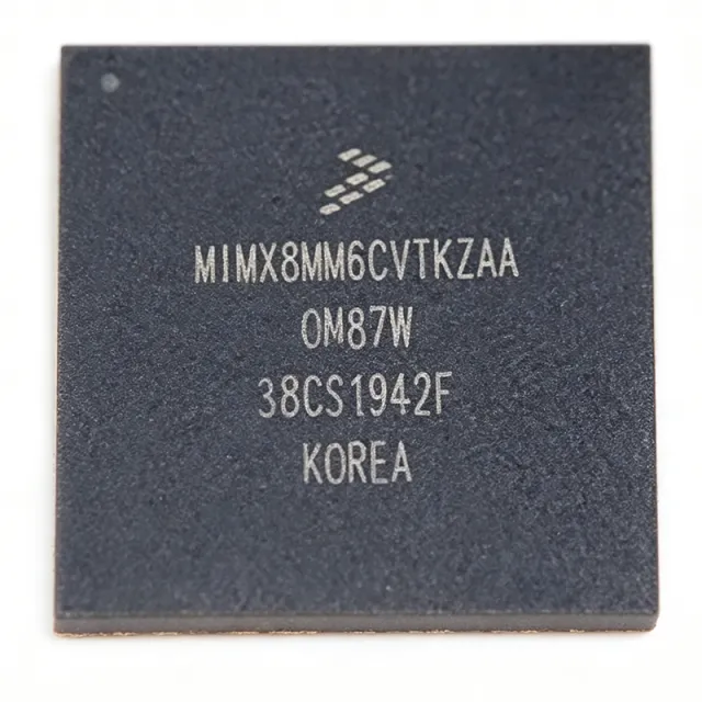
MIMX8MM6CVTKZAA - i.MX8MM Quad A53 1.6GHz SoC | NXP
MIMX8MM6CVTKZAA

MIMX8MM6CVTKZAA - i.MX8MM Quad A53 1.6GHz SoC | NXP

The NXP Semiconductors MIMX8MM6CVTKZAA is a high-performance embedded applications processor from the i.MX 8M Mini family, built on advanced 14LPC FinFET process technology. It integrates a quad-core ARM Cortex-A53 application processor running at up to 1.6GHz along with a Cortex-M4F core for real-time processing, housed in a 486-ball LFBGA package (14x14 mm) for industrial and consumer applications balancing performance, power efficiency, and multimedia capabilities. An applications processor is a system-on-chip (SoC) designed to run operating systems such as embedded Linux and complex application software on ARM architecture. It integrates CPU cores, memory controllers, graphics, and I/O interfaces, serving as the main processing unit in smart home hubs, IoT gateways, and industrial control systems. The i.MX 8M Mini sits between the lower-power i.MX 6 series and the higher-performance i.MX 8M Quad/Plus in the embedded processor hierarchy. Key features include the 64-bit quad-core Cortex-A53 cluster at 1.6GHz, a Cortex-M4F core for low-latency deterministic control, a 3D GPU (GC NanoUltra), a 2D GPU, and a 4K VPU for video encode/decode. Memory support covers LPDDR4/DDR4, and connectivity includes Gigabit Ethernet, USB 3.0, PCIe, and multiple display interfaces. Technically, the 14LPC FinFET process delivers improved power efficiency versus older planar nodes. The heterogeneous multicore architecture partitions tasks between the A53 cluster and the M4F core, enabling efficient power management. TrustZone support provides secure boot and secure execution for secure IoT deployments. Typical applications include smart home hubs, IoT gateways, industrial HMI, medical devices, and multimedia streaming devices, where combined CPU, GPU, VPU, and connectivity resources suit edge computing and AI inference. Design tip: pay careful attention to power sequencing and thermal management. The 486-ball LFBGA requires a multi-layer PCB with thermal vias and a solid ground plane, plus proper decoupling capacitors near power pins for stable operation.

USD $16.40 문의하기
MIMX8QM5CVUFFAB - i.MX 8QuadMax 8-Core SoC | NXP | 1313-BGA
MIMX8QM5CVUFFAB

MIMX8QM5CVUFFAB - i.MX 8QuadMax 8-Core SoC | NXP | 1313-BGA

The NXP Semiconductors MIMX8QM5CVUFFAB is the i.MX 8QuadMax application processor, a heterogeneous eight-core System on Chip (SoC) integrating two Arm Cortex-A72, four Arm Cortex-A53, and two Arm Cortex-M4F cores in a 1313-ball FBGA package measuring 29x29 mm with automotive temperature grade. An SoC (System on Chip) consolidates CPU, GPU, memory interfaces, and peripheral controllers into a single integrated circuit, forming the complete computing heart of an embedded system. The i.MX 8QuadMax sits at the top of the NXP i.MX 8 family (alongside 8QuadPlus and 8DualMax), targeting high-performance automotive, industrial, and consumer platforms that need advanced graphics, vision processing, and deterministic real-time control in one device. Key features include full-chip hardware virtualization with domain protection for secure multi-OS operation, independent graphics across four HD displays or one 4K screen, an integrated vision pipeline for ADAS-class perception, and an audio subsystem optimized for voice and speech recognition. The dual Cortex-A72 cores handle heavy application workloads, the quad Cortex-A53 cores provide power-efficient scaling, and the dual Cortex-M4F cores run real-time, safety-relevant tasks - a heterogeneous balance of throughput and efficiency. The architecture supports Android, Linux, FreeRTOS, QNX, Green Hills, and Dornerworks XEN operating systems, and the family offers pin- and power-compatible packages for hardware design reuse. Typical applications include automotive digital cockpits, infotainment, ADAS vision systems, industrial HMI panels, and medical imaging equipment, where rich UI and real-time control must coexist. Design consideration: the 1313-ball BGA demands a multi-layer PCB with thermal vias and strict power sequencing; the MSL 3 rating (168-hour floor life) requires controlled moisture handling before reflow.

견적 요청 문의하기
MIMXRT1061CVJ5B - 528MHz Cortex-M7 MCU | NXP | Industrial
MIMXRT1061CVJ5B

MIMXRT1061CVJ5B - 528MHz Cortex-M7 MCU | NXP | Industrial

The NXP Semiconductors MIMXRT1061CVJ5B is a 32-bit Arm Cortex-M7 crossover microprocessor operating up to 528 MHz, packaged in a 196-ball LFBGA measuring 12 x 12 mm. The device combines real-time MCU responsiveness with high-performance crossover-processor integration, supporting demanding industrial, networking, and embedded-control applications. A crossover processor is a semiconductor category that combines microcontroller real-time operation with higher-level processing capabilities. Unlike a conventional microcontroller optimized around deterministic peripheral control, the i.MX RT1060 family provides extensive connectivity, memory interfaces, security features, and graphical-media acceleration for connected embedded systems. The Arm Cortex-M7 architecture belongs to the microcontroller processor hierarchy and executes from tightly coupled memory for predictable control performance. According to the verified product listings, the MIMXRT1061CVJ5B is identified as an RT1060 device with a 528 MHz Cortex-M7 core and a 196-LFBGA package. Distributor and aggregator listings also identify this orderable configuration as a fixed USB variant. The package uses bottom-side ball terminals and surface-mount assembly, making careful PCB escape routing and thermal management essential. The i.MX RT1060 crossover-processor family is designed to bridge MCU-class control and higher-end embedded workloads. Its integrated feature set supports connected industrial equipment, human-machine interfaces, communications infrastructure, and real-time control systems. A separate NXP cross-reference result for the DVL6B variant advertises a 600 MHz Cortex-M7 core, but that variant is not treated as a drop-in substitute because its verified frequency differs by approximately 13.6 percent and other ordering details are not established here. Typical design use includes industrial gateways, connected controllers, operator panels, building automation equipment, and networked sensors. The device can manage communication tasks alongside deterministic peripheral control without adopting a higher-power application-processor architecture. Developers should confirm memory configuration, pin multiplexing, peripheral availability, clock limits, security features, and package-level routing against the official NXP datasheet before release. For PCB implementation, follow the manufacturer land pattern, ball-pitch, via, and decoupling guidance rather than generic BGA rules. Validate high-speed memory and communication interfaces with controlled-impedance routing, continuous reference planes, and signal-integrity simulations. Production designs should also review errata, boot configuration, power sequencing, firmware support, and long-term availability. This page consolidates verified NXP and distributor information, exact package identification, application guidance, design cautions, and candid replacement analysis. It distinguishes confirmed data from parameters that still require datasheet verification so procurement and engineering teams can evaluate the part efficiently without mistaking assumptions for released specifications.

견적 요청 문의하기
MIMXRT1061CVL5B - 600MHz Cortex-M7 Crossover MCU | NXP
MIMXRT1061CVL5B

MIMXRT1061CVL5B - 600MHz Cortex-M7 Crossover MCU | NXP

The NXP MIMXRT1061CVL5B is a 32-bit crossover microcontroller built around an ARM Cortex-M7 core running up to 528 MHz (with the silicon capable of 600 MHz in the RT1061 family) and housed in a 196-ball MAPBGA package measuring 10x10 mm. According to the NXP product page, this RT1060-family industrial-grade MCU integrates 1 MB of on-chip SRAM and supports external memory through SEMC, FlexSPI, and parallel interfaces, delivering real-time signal processing for industrial control, motor drives, and human-machine interface applications. A crossover microcontroller combines the high-performance characteristics of an application processor (e.g., GHz clock, large memory) with the deterministic real-time response and low power of a microcontroller. Within the broader taxonomy, the MIMXRT1061 sits in the crossover MCU segment bridging high-end microcontrollers and entry-level application processors, complementing NXP's i.MX 8M family. Its 196-ball MAPBGA provides ample I/O for advanced peripherals including dual Ethernet, USB, CAN-FD, and a 12-bit ADC. Key features include an integrated LCDIF controller supporting up to WXGA displays, dual FlexSPI interfaces for high-speed external flash, a 12-bit ADC with up to 20 channels, and an integrated power management IC (PMIC) companion interface. The Cortex-M7 core delivers 2.14 CoreMark/MHz performance with double-precision FPU, DSP extensions, and L1 cache (16 KB I-cache and 16 KB D-cache). Hardware encryption is provided through the Bus Encryption Engine (BEE) for secure external flash execution. The RT1061 architecture implements a 4-channel eDMA, FlexTimer (FTM) modules for PWM generation, and a flexible peripheral crossbar for pin mapping. Operating voltage spans 3V to 3.6V with internal DCDC and LDO regulators generating core rails. The device supports industrial temperature ranges of -40C to +105C for harsh-environment deployments. Typical applications include industrial HMI panels with LCD displays, motor control and field-oriented control (FOC) drives, building automation controllers, point-of-sale terminals, and edge IoT gateways. The 528 MHz operation with DSP extensions makes it suitable for predictive maintenance algorithms running on-device. When designing with this part, ensure proper PCB layout for the 196-ball MAPBGA with via-in-pad or dog-bone fanout, and follow NXP's hardware design guide for DDR3L memory routing. The internal PMIC companion requires careful sequencing of DCDC outputs for clean power-up. This page synthesizes distributor pricing, drop-in package alternatives within the RT106x family, and design notes extracted from the NXP datasheet and community support threads.

견적 요청 문의하기
MIMXRT1062DVL6B - i.MX RT1062 600MHz Cortex-M7 MCU | NXP
MIMXRT1062DVL6B

MIMXRT1062DVL6B - i.MX RT1062 600MHz Cortex-M7 MCU | NXP

The NXP MIMXRT1062DVL6B is a high-performance crossover microprocessor featuring an Arm Cortex-M7 core running at 600 MHz with 1 MB of on-chip SRAM, housed in a 196-ball LFBGA (10x10 mm) package. It belongs to the i.MX RT1060 family, blending microcontroller responsiveness with application-processor throughput for consumer products. The device integrates advanced peripherals including an LCD controller, 2D graphics accelerator (PxP), CSI camera interface, and FlexSPI for external memory expansion. What is a crossover processor? A crossover processor combines the real-time deterministic behavior of a microcontroller (MCU) with the high performance and rich multimedia features of an application processor (MPU). It bridges the architectural gap between Cortex-M MCUs and Cortex-A MPUs, sitting in the product-type hierarchy as: microcontroller -> crossover processor -> embedded processor -> semiconductor IC. This category targets applications requiring real-time DSP, graphics, and high-speed connectivity without the overhead of a full Linux-capable MPU. Key features include 600 MHz Cortex-M7 with single-precision and double-precision FPU, 1 MB on-chip SRAM, dual FlexSPI for QSPI/NOR/NAND expansion, integrated LCDIF display controller up to WXGA resolution, USB 2.0 OTG with PHY, 10/100 Mbit Ethernet MAC, 8-bit CMOS sensor interface (CSI), and 2D PxP engine. The part operates from 0.95 V to 1.05 V core and 3.0 V to 3.6 V I/O supplies, with industrial-grade temperature support. The architecture leverages the Cortex-M7 superscalar pipeline with tightly-coupled memory for deterministic interrupt response, paired with NXP's SmartDMA and eFuse-based secure boot. The 196-ball LFBGA provides ample I/O routing for high-speed parallel buses and multiple serial interfaces (SPI, I2C, UART, CAN, FlexCAN, SAI). Hardware cryptography via CAAM and TrustZone-M for isolation are integrated for secure IoT edge designs. Typical applications include HMI panels for industrial and home appliances, USB audio devices with display, motor control inverters, smart-home gateways, low-cost HMI for IoT edge nodes, and point-of-sale terminals. The wide peripheral set lets designers replace legacy MCU + external controller stacks with a single chip. When designing with this part, ensure the PCB provides sufficient thermal dissipation; the LFBGA package requires 6-layer stack-up with microvia-in-pad for reliable BGA assembly. SDRAM traces must be length-matched within 50 mils for DDR operation. Use the NXP MCUXpresso SDK and Config Tools for peripheral initialization and pin muxing. This page synthesizes distributor pricing, pin-compatible i.MX RT1060 family drop-in alternatives, and practical design considerations not aggregated on a single manufacturer or distributor page.

견적 요청 문의하기
MIMXRT1064CVJ5B - 528MHz Cortex-M7 Crossover MCU | NXP
MIMXRT1064CVJ5B

MIMXRT1064CVJ5B - 528MHz Cortex-M7 Crossover MCU | NXP

The NXP MIMXRT1064CVJ5B is a high-performance crossover microcontroller featuring an Arm Cortex-M7 core running at 528 MHz, 4 MB on-chip flash, and 1 MB SRAM, housed in a 196-ball LFBGA (12x12 mm) package. As a member of the i.MX RT1060 family, the part bridges the gap between Application Processors and traditional microcontrollers by delivering application-processor-class compute in an MCU-style footprint. A crossover MCU (also called a crossover processor or hybrid MCU) is a class of microcontrollers that combines the high CPU performance and rich peripherals of an applications processor with the deterministic real-time response and ease-of-use of a microcontroller. The MIMXRT1064CVJ5B inherits this architecture, sitting in the broader taxonomy of microcontroller -> embedded MCU -> crossover MCU -> real-time control processor -> semiconductor. It is engineered for industrial IoT, HMI, and motor-control applications that demand both high throughput and deterministic real-time behavior. Key features include 4 MB on-chip flash, 1 MB SRAM (configurable as TCM, OCRAM, or DTCM), dual USB 2.0 OTG controllers with PHY, integrated 2D graphics acceleration engine (PxP), MIPI-CSI and parallel display interfaces, hardware encryption (AES, TRNG, secure boot), and 3x FlexCAN plus 2x Ethernet (10/100M). The 196-LFBGA package exposes a rich GPIO set and a wide peripheral mix designed to replace multi-chip MCU+DRAM solutions with a single BGA. The internal bus matrix and dual-issue pipeline allow the Cortex-M7 core to execute from tightly-coupled memory with single-wait-state access, enabling benchmark scores above 1280 CoreMark while keeping interrupt latency deterministic. On-chip regulators, integrated power management, and support for low-power modes make the device suitable for both line-powered industrial designs and battery-aware edge nodes. Typical applications include industrial human-machine interfaces, edge IoT gateways, motor control drives, audio subsystems, and graphics-rich consumer devices. The wide peripheral set also suits Point-of-Sale terminals, building automation, and connected appliances. Designers choose this part when they need Cortex-M7-class DSP and FPU throughput without migrating to a Linux-capable MPU. When designing with this device, allocate sufficient PCB copper under the BGA for thermal dissipation and route high-speed interfaces (MIPI-CSI, parallel display, RMII) with controlled-impedance traces. Plan supply sequencing for the multiple internal rails and follow the NXP hardware development guide for boot mode configuration (boot source, SD/eMMC, SPI flash) to avoid bricked prototypes. This page consolidates distributor pricing for the 196-LFBGA package, drop-in i.MX RT1064 family variants, and practical design considerations not always obvious from the manufacturer datasheet, helping procurement, EE, and firmware engineers choose the right crossover MCU for industrial and IoT designs.

견적 요청 문의하기
MIMXRT1064CVL5A - 528MHz Cortex-M7 MCU 4MB Flash | NXP i.MX RT1064
MIMXRT1064CVL5A

MIMXRT1064CVL5A - 528MHz Cortex-M7 MCU 4MB Flash | NXP i.MX RT1064

The NXP Semiconductors MIMXRT1064CVL5A is a 32-bit crossover microcontroller built around the Arm Cortex-M7 core running at up to 528 MHz, with 4 MB of on-chip flash and 1 MB of on-chip SRAM, housed in a 196-pin LFBGA package. It provides real-time deterministic performance with rich multimedia peripherals, dual USB, 10/100 Mbit Ethernet, and an LCD controller suitable for industrial HMI. Background: A crossover microcontroller (cMCU) combines the deterministic real-time response of a microcontroller (MCU) with the high CPU performance and multimedia features typical of a microprocessor (MPU). The i.MX RT1064 belongs to the i.MX RT family, which occupies the architectural niche between traditional Cortex-M microcontrollers (no MMU, no on-chip flash) and Cortex-A microprocessors (full application processor). The 'RT' suffix signals real-time control with no external SDRAM requirement at boot because of the integrated 4 MB flash - this is the first i.MX RT family member to include on-chip flash according to NXP documentation. Key features include the 528 MHz Cortex-M7 core with single-precision and double-precision FPU, 4 MB on-chip flash, 1 MB on-chip SRAM (configurable as TCM and OCRAM), dual USB 2.0 with PHY, 10/100 Mbit Ethernet MAC, 8/16-bit CSI camera interface, 24-bit LCD controller up to WXGA resolution, and a wide range of serial interfaces (UART, SPI, I2C, I2S, FlexIO, FlexCAN, FlexPWM). The LFBGA-196 package provides ample I/O for industrial gateway, motor drive, and HMI applications. Typical applications include industrial HMI panels, IoT gateways, motor control and drives, audio subsystems, point-of-sale terminals, and smart appliance controllers. The integrated LCD controller and 2D graphics acceleration GPU enable cost-effective graphical touch interfaces without an external graphics controller. Design consideration: the LFBGA-196 package requires a 4-layer minimum PCB with microvia or laser-drilled via technology for fan-out. Plan for thermal copper mass under the exposed die paddle and verify IO bank voltage sequencing against the System Reset and Boot Mode Reference Manual before finalizing the schematic. This page synthesizes distributor pricing, drop-in alternatives, and practical design notes not found in the manufacturer datasheet.

견적 요청 문의하기
MIMXRT1064CVL5B - i.MX RT1064 Crossover MCU 600MHz | NXP
MIMXRT1064CVL5B

MIMXRT1064CVL5B - i.MX RT1064 Crossover MCU 600MHz | NXP

The NXP Semiconductors MIMXRT1064CVL5B is a high-performance crossover microcontroller built on the Arm Cortex-M7 core running at up to 600 MHz, integrating 4 MB of on-chip Flash and 1 MB of on-chip SRAM in a 196-ball MAPBGA package measuring 10x10 mm with 0.65 mm pitch. The device is the USB-equipped variant of the i.MX RT1064 family, targets industrial operating conditions from -40C to +105C, and combines MCU-class deterministic real-time response with application-processor multimedia throughput. A crossover MCU is a class of embedded processor that bridges the gap between traditional microcontrollers (deterministic, low-power, easy-to-use) and application processors (high performance, rich peripherals). By integrating a Cortex-M7 core with tightly coupled memory, large SRAM, and high-speed peripherals like USB 2.0 with PHY, the i.MX RT1064 lets designers run graphical user interfaces, audio pipelines, and edge inference workloads on a single chip without an external Linux MPU. Key features of the MIMXRT1064CVL5B include the 600 MHz Cortex-M7 with single-precision and double-precision FPU, 4 MB Flash, 1 MB SRAM, a dedicated 2D graphics accelerator (PxP), an LCDIF display controller supporting up to WXGA resolution, two USB 2.0 controllers (one with integrated HS PHY), two 12-bit ADC modules totaling 20 channels, FlexIO for flexible serial emulation, and a comprehensive security subsystem including High Assurance Boot and on-the-fly AES decryption (OTFAD). The 196-MAPBGA package provides sufficient I/O for demanding industrial designs while fitting within a 10x10 mm footprint. Architecturally, the RT1064 leverages NXP's advanced 40 nm low-power process and a sophisticated bus matrix that allows concurrent DMA-driven data movement between peripherals and SRAM, leaving the Cortex-M7 core free for application logic. The integrated LCDIF and PxP blocks offload display composition, allowing the core to focus on real-time control loops. Typical applications include industrial human-machine interfaces (HMIs), building automation control panels, point-of-sale terminals, edge IoT gateways with on-screen visualization, USB-equipped audio devices, and low-latency motor control with integrated display feedback. The wide temperature range and AEC-Q100-style qualification flow also make the part attractive in non-automotive industrial segments. When designing with this device, pay close attention to PCB layout: the 0.65 mm pitch MAPBGA requires microvia stack-ups and matched-length routing for the DDR-style memory interfaces. Confirm that your selected power management IC can deliver the dynamic load currents demanded by the Cortex-M7 at full speed. This page synthesizes distributor pricing, drop-in pin-compatible alternatives within the i.MX RT family, and practical PCB-layout and thermal design notes that go beyond what the datasheet alone provides.

견적 요청 문의하기
MIMXRT1064DVL6A - i.MX RT1064 600MHz M7 Crossover MCU | NXP
MIMXRT1064DVL6A

MIMXRT1064DVL6A - i.MX RT1064 600MHz M7 Crossover MCU | NXP

The NXP Semiconductors MIMXRT1064DVL6A is an i.MX RT1064 crossover microcontroller combining an Arm Cortex-M7 core running at up to 600 MHz with 4 MB of on-chip flash and 1 MB of on-chip SRAM in a 196-ball LFBGA package (10 mm x 10 mm). The part is pin-to-pin compatible with i.MX RT1050 and i.MX RT1060 family members, allowing designs to migrate upward to additional flash density or to retain a single PCB layout across the family. What is a crossover MCU? A crossover microcontroller combines the high-performance real-time processing of a microcontroller (deterministic interrupt response, simple programming model) with the application-processor-like peripheral set and clock speed typical of an applications processor. The i.MX RT1064 sits in the power-management IC (PMIC) ecosystem between traditional Cortex-M4 MCUs and Cortex-A-class application processors, and is positioned in the broader NXP i.MX product family that also includes i.MX 6/7/8 application processors. Key features of the MIMXRT1064DVL6A include 4 MB on-chip flash (the first i.MX RT family to integrate on-chip flash), 1 MB on-chip SRAM with configurable RAM partitioning, and a rich peripheral set including dual USB 2.0 with PHY, dual CAN-FD, dual SDIO/eMMC, two SAI/I2S audio interfaces, two camera interfaces (CSI), an LCDIF controller for displays up to WXGA, a 10/100-Mbit Ethernet MAC, and hardware cryptography acceleration (AES, SHA, TRNG). The 600 MHz core delivers 1284 CoreMark and 3010 DMIPS, while an integrated FPU and DSP extensions accelerate floating-point and signal-processing code paths. Typical applications for the MIMXRT1064DVL6A include industrial HMI panels, audio subsystems with display, IoT edge gateways, point-of-sale terminals, motor control and home appliance controllers, and low-cost audio/video consumer devices. The on-chip flash reduces BOM cost and PCB area relative to i.MX RT parts requiring external QSPI flash. When designing with this MCU, allocate careful attention to decoupling (the 600 MHz core demands dense, low-impedance power distribution), PCB stackup (the 10 mm x 10 mm 196-LFBGA package has a 0.65 mm ball pitch and requires microvia PCB fabrication), and boot-mode configuration via the BOOT_MODE pins. DDR memory routing must follow length-matching rules documented in the hardware user guide. This page synthesizes distributor pricing, drop-in alternatives, and practical design notes not found in the manufacturer datasheet alone.

견적 요청 문의하기
MIMXRT595SFFOC - 200MHz Cortex-M33 with 32MB Flash | NXP
MIMXRT595SFFOC

MIMXRT595SFFOC - 200MHz Cortex-M33 with 32MB Flash | NXP

The NXP Semiconductors MIMXRT595SFFOC is a 200 MHz Arm Cortex-M33 crossover microcontroller with 32 MB of octal flash memory, graphics acceleration, hardware encryption, and low-power operating modes in a 249-pin FOWLP package. The 7 x 7 mm package supports integrated external-memory interfaces and advanced human-machine-interface processing in a compact footprint. An i.MX RT crossover microcontroller combines the deterministic real-time control characteristics of a microcontroller with the high-level graphics and connected-processing capabilities normally associated with application processors. This positioning makes the MIMXRT595SFFOC suitable for industrial panels, building controls, medical terminals, gateways, and graphical embedded products that require responsive peripherals alongside sophisticated display support. Key features include a 200 MHz Arm Cortex-M33 processor core, 32 MB of octal flash, hardware encryption, graphics acceleration, and operation from 1.8 V, 2.5 V, or 3.3 V supply levels. NXP positions the device for secure, low-power Internet of Things applications. The on-chip flash also removes the need for a separate external boot-flash device in designs where its capacity and programming characteristics satisfy the application requirements. The part uses an integrated dual-core architecture combining a Cortex-M33 core with a Cortex-M7 core for higher-performance workloads. Its external memory interfaces allow designs to extend storage or connect additional peripherals, while dedicated graphics acceleration handles display-oriented workloads without placing the full burden on the general-purpose processor. Hardware encryption protects stored code and data against unauthorized access when the associated security features are enabled in the system design. Typical applications include industrial human-machine interfaces, smart-building control panels, medical-device user interfaces, connected gateways, and low-power IoT controllers. The 249-pin FOWLP package is supplied in a tray configuration. Board design should treat this package as a high-pin-count, fine-pitch assembly and follow the land pattern, escape-routing, and reflow guidance in the NXP data sheet. The main design consideration is that this MCU integrates substantially more flash and graphics capability than a conventional small Cortex-M33 device, so firmware architecture, external peripheral routing, and package escape routing require early planning. Confirm pin multiplexing, power sequencing, memory timing, and exposed-pad requirements against the current NXP documentation before committing the PCB layout. This page organizes the verified product characteristics of the MIMXRT595SFFOC together with application guidance, package details, design notes, and comparison parameters. It helps engineers evaluate the processor, memory configuration, security functions, graphics support, and power options before beginning hardware design.

견적 요청 문의하기