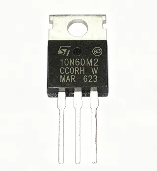
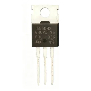
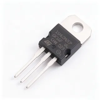
STP12N60M2 - 12A, 600V N-Channel Power MOSFET | STMicroelectronics
부품 번호: STP12N60M2 ✓ 활성| 수량 | 단가 | 합계 |
|---|---|---|
| 1 | $1.85 | $1.85 |
| 10 | $1.66 | $16.60 |
| 100 | $1.48 | $148.00 |
| 500 | $1.33 | $665.00 |
| 1,000 | $1.2 | $1,200.00 |
STP12N60M2 개요
A Power MOSFET is a type of field-effect transistor optimized for switching and amplification in power electronics. It operates by controlling the conductivity between the drain and source terminals through an insulated gate voltage. Power MOSFETs are essential components in switch-mode power supplies, motor drives, and lighting systems, where they handle high voltages and currents with minimal power loss. They are part of the broader family of discrete semiconductors, which also includes diodes, thyristors, and IGBTs.
Key features of the STP12N60M2 include a low gate charge (Qg) of 30nC, which enables fast switching and reduced switching losses, and a high dv/dt capability for robust performance in hard-switching topologies. The device also features 100% avalanche tested, ensuring reliability under extreme conditions. Its low on-resistance minimizes conduction losses, improving overall system efficiency.
The STP12N60M2 utilizes ST's MDmesh M2 technology, which combines a vertical structure with a charge-balanced layout to achieve low on-resistance and high breakdown voltage simultaneously. This technology reduces the figure of merit (RDS(on) × Qg), making it suitable for high-frequency applications where efficiency is critical. The device also includes an intrinsic body diode with fast recovery characteristics, beneficial for bridge topologies.
Typical applications include switch-mode power supplies (SMPS), power factor correction (PFC) circuits, LED lighting drivers, and motor control systems. In SMPS, the STP12N60M2 can be used in the primary side of flyback or forward converters, where its high voltage rating and low losses contribute to compact, efficient designs. In PFC circuits, it handles high voltage stress while maintaining low conduction losses.
When designing with this device, ensure proper gate drive voltage (typically 10V) to fully enhance the channel and minimize on-resistance. Consider the thermal resistance of the TO-220 package (62.5°C/W junction-to-ambient) and use a heatsink for high-power applications. Also, provide adequate gate protection against voltage spikes, as the maximum gate-source voltage is ±25V.
드롭인 대체품: STP12N60M2 — 동일 패키지, 핀 호환. PCB 재작업이 필요한 다른 패키지 부품은 제외됩니다.
빠른 비교 도구 — 나란히 비교할 대체 부품을 선택하십시오:
STP12N60M2-EP
✅ 드롭인 ⚠️ 사양 미검증📋 참조 대체품 (카탈로그에 없음)
STP12N60M2FP
⚡ 동일 패키지 ⚠️ 사양 미검증📋 참조 대체품 (카탈로그에 없음)
IPP60R099CP
✅ 드롭인 ⚠️ 사양 미검증📋 참조 대체품 (카탈로그에 없음)
FCP12N60
✅ 드롭인 ⚠️ 사양 미검증📋 참조 대체품 (카탈로그에 없음)
TK12A60D
✅ 드롭인 ⚠️ 사양 미검증📋 참조 대체품 (카탈로그에 없음)
STP12N60M2 최대 정격 & 전기적 특성
| Polarity | N-Channel |
| Drain-Source Voltage (VDS) | 600 V |
| Continuous Drain Current (ID) at 25°C | 12 A |
| On-Resistance (RDS(on)) | 0.38 Ω typical |
| Gate Charge (Qg) | 30 nC |
| Gate-Source Voltage (VGS) | ±25 V |
| 패키지 | TO-220 |
| 실장 유형 | Through Hole |
| Technology | MDmesh M2 |
| Avalanche Energy Rating | 100% avalanche tested |
| 열 저항, 접합-주변 | 62.5 °C/W |
| RoHS 상태 | Compliant |
| Body Diode Recovery | Fast recovery |
STP12N60M2 핀 구성
| 핀 1 | Gate — Gate terminal for controlling the MOSFET |
| 핀 2 | Drain — Drain terminal, connected to the heatsink tab |
| 핀 3 | Source — Source terminal |
안전 동작 영역
일반적인 애플리케이션
STP12N60M2 적합 용도: 6 애플리케이션s: Switch-Mode Power Supplies (SMPS), Power Factor Correction (PFC), LED Lighting Drivers, Motor Control, Solar Inverters, Battery Chargers.
Switch-Mode Power Supplies (SMPS)
The STP12N60M2 is ideal for SMPS primary-side switching due to its 600V breakdown voltage and low on-resistance. In a flyback converter, it can handle high voltage stress while minimizing conduction losses. The low gate charge (30nC) enables fast switching, reducing switching losses and improving efficiency. Designers should ensure proper gate drive (10V) and use a heatsink for high-power operation.
추천
Power Factor Correction (PFC)
In PFC boost converters, the STP12N60M2 handles high voltage stress (up to 600V) while maintaining low conduction losses. Its fast body diode recovery is beneficial for continuous conduction mode (CCM) operation. The low on-resistance (0.38Ω) reduces power dissipation, improving overall efficiency. Designers should consider the thermal resistance (62.5°C/W) and use adequate heatsinking.
추천
LED Lighting Drivers
The STP12N60M2 is suitable for LED drivers requiring high voltage and current handling. Its 600V rating allows direct connection to rectified mains (up to 400V DC). The low gate charge enables high-frequency switching, reducing the size of magnetic components. The device's avalanche ruggedness ensures reliability in transient conditions. Use a heatsink for continuous operation at high currents.
추천
Motor Control
In motor control applications, the STP12N60M2 can be used in the inverter stage of variable frequency drives. Its 600V rating is suitable for 230V AC motor drives. The fast switching capability reduces switching losses, and the low on-resistance minimizes conduction losses. The body diode's fast recovery is beneficial for freewheeling currents. Ensure proper gate drive and snubber circuits for inductive loads.
추천
Solar Inverters
The STP12N60M2 is used in solar inverter DC-DC boost stages and inverter bridges. Its high voltage rating (600V) is suitable for photovoltaic panel voltages. The low on-resistance reduces losses, improving conversion efficiency. The device's avalanche ruggedness ensures reliability under lightning-induced transients. Designers should consider thermal management for outdoor operation.
추천
Battery Chargers
In battery chargers, the STP12N60M2 is used in the power stage to convert AC to DC. Its 600V rating allows direct connection to mains. The low gate charge enables efficient high-frequency switching, reducing transformer size. The device's low on-resistance minimizes heat generation. Use a heatsink for continuous charging at high currents.
추천
추천 제품 요약
엔지니어링 참조 데이터: STP12N60M2 — 비교, 설계 지침 및 규정 준수 정보.
선택 가이드
대체품과의 비교
| 파라미터 | 이 제품 | STP12N60M2-EP | IPP60R099CP | FCP12N60 |
|---|---|---|---|---|
| Package | TO-220 | TO-220 | TO-220 | TO-220 |
| Brand | STMicroelectronics | STMicroelectronics | Infineon | onsemi |
| Drain-Source Voltage (VDS) | 600 V | 600 V | 600 V | 600 V |
| Continuous Drain Current (ID) | 12 A | 12 A | 12 A | 12 A |
| On-Resistance (RDS(on)) | 0.38 Ω | 0.38 Ω | 0.099 Ω | 0.38 Ω |
| Gate Charge (Qg) | 30 nC | 30 nC | 45 nC | 30 nC |
| Avalanche Ruggedness | 100% tested | Enhanced | 100% tested | 100% tested |
주요 차별점
- Low gate charge (30nC) enables fast switching (vs IPP60R099CP)
- 100% avalanche tested for reliability (vs FCP12N60)
- Enhanced version available (STP12N60M2-EP) (vs IPP60R099CP)
설계 노트
The STP12N60M2 has a junction-to-ambient thermal resistance of 62.5°C/W. For high-power applications, a heatsink is essential. For example, at 12A and 0.38Ω, conduction losses are approximately 55W, which would cause a temperature rise of over 3400°C without a heatsink. Use a heatsink with a thermal resistance of less than 1°C/W for reliable operation.
For TO-220 packages, ensure the drain tab is properly soldered to a large copper area for heat dissipation. Keep the gate drive traces short and use a gate resistor (typically 10Ω) to reduce ringing. Place a 100nF ceramic capacitor close to the gate-source terminals to suppress high-frequency noise.
Do not exceed the maximum gate-source voltage of ±25V. Use a zener diode or TVS for gate protection. Also, ensure the drain-source voltage does not exceed 600V, especially during switching transients. Consider using a snubber circuit to limit voltage spikes in inductive load switching.
규정 준수 정보
RoHS compliance confirmed from STMicroelectronics product page. Other compliance data not available in provided data.