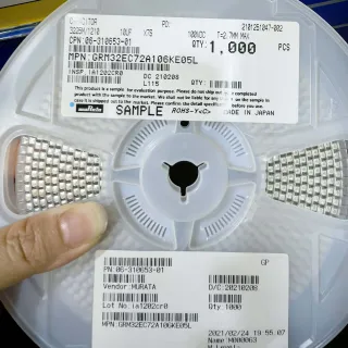
06033W106MAT2A - 10uF 25V X6S MLCC 0603 | KYOCERA AVX
MPN: 06033W106MAT2A ✓ Active| Qty | Unit Price | Extended |
|---|---|---|
| 1 | $0.18 | $0.18 |
| 10 | $0.12 | $1.20 |
| 100 | $0.072 | $7.20 |
| 500 | $0.048 | $24.00 |
| 1,000 | $0.035 | $35.00 |
| 3,000 | $0.028 | $84.00 |
Drop-in alternatives for 06033W106MAT2A — same package, pin-to-pin compatible. Different-package parts requiring PCB rework are excluded.
Quick Comparison Tool — Select alternative parts for side-by-side comparison:
KGM15CS61E106MT
✅ Drop-In📋 Reference alternative (not in catalog)
06033C106MAT2A
✅ Drop-In ⚠️ 参数待验证📋 Reference alternative (not in catalog)
06033W106MAT2A Maximum Ratings & Electrical Characteristics
| Capacitance | 10 uF |
| Capacitance Tolerance | ±20% |
| Rated Voltage (DC) | 25 V |
| Dielectric | X6S (Class II) |
| Operating Temperature Range | -55°C to +105°C |
| Case Size | 0603 (1608 Metric) |
| Case Dimensions | 1.60 mm x 0.80 mm |
| Mounting Type | Surface Mount (SMD/SMT) |
| Polarization | Non-polarized |
| Termination Style | SMD termination (MAT2A variant per AVX coding) |
| Failure Rate / Reliability Grade | Standard (non-automotive grade per listing) |
| RoHS Status | Compliant (per DigiKey listing category) |
| Product Family | KYOCERA AVX surface-mount multilayer ceramic capacitors (MLCC) |
06033W106MAT2A Pin Configuration
| Pin 1 | Terminal 1 — Non-polarized capacitor terminal 1 (no polarity requirement) |
| Pin 2 | Terminal 2 — Non-polarized capacitor terminal 2 (no polarity requirement) |
Safe Operating Area (SOA) & Thermal Characteristics
No official SOA curve available for this component. Always operate within absolute maximum ratings specified in the datasheet. Ensure adequate cooling and derate as needed.
Typical Applications
06033W106MAT2A is suitable for 6 applications: Microcontroller and FPGA Power Decoupling, DC-DC Converter Output Filtering, Industrial 24 V Equipment Signal Conditioning, Automotive-Adjacent ECUs and Body Electronics, Portable and Wearable Device Power Rails, Gate Driver and Motor Control Bias Rails.
Microcontroller and FPGA Power Decoupling
The 06033W106MAT2A provides 10 uF of local charge storage in a 1.60 x 0.80 mm footprint, making it ideal for decoupling the core and I/O rails of microcontrollers and FPGAs where board density limits how many capacitors can sit near each power pin. Its X6S dielectric maintains usable capacitance from -55°C to +105°C, and its low ESR efficiently shunts high-frequency switching transients. Place one part adjacent to each rail entry point with short, wide traces; because Class II capacitance derates with DC bias, verify effective capacitance at the rail voltage and add a parallel 0.1 uF X7R for very high frequency decoupling.
Recommended
DC-DC Converter Output Filtering
In buck and boost converter outputs, the 06033W106MAT2A supplies 10 uF of output capacitance at 25 V, covering 12 V and 19 V rails with margin. Its low ESR reduces output ripple, but designers must confirm the converter's control loop tolerates low-ESR ceramic outputs - most modern regulators are designed for all-ceramic output filters. The X6S temperature rating to +105°C suits power supplies near heat sources. Because effective capacitance drops with the DC bias on the output rail, size the capacitor count so that the bias-derated value still meets the ripple and transient-response targets of the design.
Recommended
Industrial 24 V Equipment Signal Conditioning
Industrial analog front ends and sensor conditioners running from 24 V-derived rails benefit from the 06033W106MAT2A's 25 V rating and stable X6S behavior across the full -55°C to +105°C industrial temperature range. Used as local bulk and mid-frequency bypass near ADCs, op-amps, and isolation barriers, it reduces rail noise that would otherwise degrade measurement accuracy. At rails near 24 V, apply conservative derating (consider parallel parts or a 50 V-rated sibling for highest reliability) and confirm effective capacitance at the working bias with the manufacturer's DC-bias curves before finalizing the filter design.
Recommended
Automotive-Adjacent ECUs and Body Electronics
The X6S dielectric's -55°C to +105°C range and compact 0603 case suit engine-bay-adjacent modules, body control units, and lighting electronics where underhood temperatures approach 105°C and board space is scarce. The 06033W106MAT2A decouples sensor supplies, transceiver rails, and gate-driver bias rails at up to 25 V. Note this listing is the standard commercial grade rather than a dedicated AEC-Q200 automotive-qualified variant, so for formal automotive programs verify the AVX automotive-series equivalent or add appropriate qualification evidence; for industrial-grade vehicle electronics it delivers high capacitance density and temperature robustness at low cost.
Recommended
Portable and Wearable Device Power Rails
Space-constrained portable electronics use the 06033W106MAT2A to put 10 uF of bulk capacitance where an 0805 or tantalum would not fit, smoothing battery-fed rails for application processors, wireless modules, and PMIC outputs. The non-polarized ceramic construction avoids tantalum derating rules and failure-mode concerns, and its 25 V rating gives wide margin on single-cell and multi-cell battery stacks. Place parts at each PMIC output and at the far ends of power routing. Watch for piezoelectric audible noise on sensitive audio rails and consider an X7R or film alternative where acoustic artifacts matter.
Recommended
Gate Driver and Motor Control Bias Rails
Motor-drive and inverter designs use the 06033W106MAT2A to stabilize 12-15 V gate-driver supply rails and bootstrap-related decoupling points, where pulsed gate-charge current creates fast, high-amplitude transients. Its low ESR and ESL deliver charge quickly during gate switching, preventing rail droop that would cause incomplete MOSFET enhancement and switching losses. The X6S rating to 105°C withstands the elevated ambient near power stages. Place one capacitor directly across each gate driver's VDD/VEE pins with minimal loop area, and verify the bias-derated capacitance still covers the total gate charge per switching event.
Recommended
Recommended Products Summary
Engineering reference data for 06033W106MAT2A — comparison, design guidance, and compliance information.
Selection Guide
Comparison with Alternatives
| Parameter | This Product | KGM15CS61E106MT | 06033C106MAT2A |
|---|---|---|---|
| Package | 0603 (1608 Metric), 1.60 x 0.80 mm | 0603 (1608 Metric) - same | 0603 (1608 Metric) - same |
| Brand | KYOCERA AVX | KYOCERA AVX | KYOCERA AVX |
| Capacitance | 10 uF | 10 uF | 10 uF |
| Rated Voltage | 25 V | 25 V | [DATA_NEEDED] |
| Dielectric | X6S | X5R-type (per TTI cross-listing) | X7R-type (verify ordering code) |
| Temperature Range | -55°C to +105°C | -55°C to +85°C (X5R-type) | -55°C to +125°C (X7R-type, verify) |
| Tolerance | ±20% | ±20% | [DATA_NEEDED] |
| Typical Use | Extended-temperature (to 105°C) decoupling | Cost-sensitive use below 85°C | Higher-temperature (X7R) decoupling |
Key Differentiators
- Extended upper temperature limit to +105°C (vs KGM15CS61E106MT)
- High capacitance density in 0603 (vs Larger-case 10 uF parts)
- Honest trade-off: higher temperature range vs cost (vs KGM15CS61E106MT)
Design Notes
Account for DC bias derating: as a Class II X6S MLCC, the 06033W106MAT2A's effective capacitance decreases significantly as applied DC voltage approaches the 25 V rating. At high bias ratios, a 10 uF nominal part may deliver substantially less effective capacitance. Consult the DC bias versus capacitance curve in the KYOCERA AVX datasheet and, if needed, use a second parallel capacitor or a higher-rated voltage code so the derated value still meets ripple and transient requirements. This is the single most common cause of underperforming MLCC-based decoupling.
Use the standard 0603 land pattern from the KYOCERA AVX datasheet with symmetric pad geometry to prevent tombstoning during reflow. Keep the capacitor as close as possible to the IC power pin, with wide, short traces and via stitching directly to the plane to minimize loop inductance. For mechanical reliability, avoid placing 0603 ceramics where board flexing occurs (near mounting holes, connectors, or panel break edges), because small, thin-dielectric, high-capacitance parts are more susceptible to flex cracking than larger cases.
Two frequent mistakes: (1) substituting an X5R part (85°C limit, e.g., KGM15CS61E106MT) into a design that reaches 100-105°C, where the dielectric is out of specification; and (2) ignoring Class II aging - X6S capacitance ages over time and with temperature excursions above the Curie point, so designs should retain margin on nominal values. Also note low ESR can destabilize some legacy LDOs; verify the regulator's stable ESR range when this part is used as an output capacitor.
Compliance Information
Provided verified web data does not include explicit compliance statements. Confirm RoHS/REACH/lead-free status on the official KYOCERA AVX datasheet or distributor compliance certificate before contract-manufacturing use.