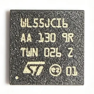
ATSAMR21G18A-MUT - 2.4GHz 802.15.4 SoC MCU | Microchip
MPN: ATSAMR21G18A-MUT ✓ Active| Qty | Unit Price | Extended |
|---|---|---|
| 1 | $8.95 | $8.95 |
| 10 | $7.82 | $78.20 |
| 100 | $6.74 | $674.00 |
| 500 | $5.91 | $2,955.00 |
| 1,000 | $5.12 | $5,120.00 |
| 3,000 | $4.46 | $13,380.00 |
ATSAMR21G18A-MUT Overview
An SoC (System-on-Chip) wireless radio combines an application processor and RF transceiver on a single die, reducing BOM count, PCB area, and BOM-driven failure modes versus two-chip MCU+radio designs. As a member of the SAM R21 family, the ATSAMR21G18A belongs to the broader 32-bit ARM Cortex-M0+ microcontroller hierarchy (ARM Cortex-M0+ -> Cortex-M0 family -> ARM Cortex-M -> 32-bit MCU -> microcontroller -> semiconductor). This category also spans wireless SoCs, RF transceivers with embedded MCUs, and short-range wireless controllers used in Thread, ZigBee, and ZigBee PRO mesh networks.
Key differentiating features include a hardware 128-bit AES crypto engine, a 32-bit MAC symbol counter for IEEE 802.15.4 security, automatic transmission modes that offload the CPU, an integrated temperature sensor, and pin-compatible migration paths to the SAM D21 family. The wide 2.5 V to 3.3 V operating range and ultra-low sleep currents extend battery life in energy-harvesting or coin-cell designs.
Typical applications include IEEE 802.15.4 sensor networks, ZigBee home-automation nodes, smart-metering endpoints, industrial wireless sensor nodes, and proprietary 2.4 GHz point-to-point links. The SAM R21 family is supported by the Atmel/Microchip Studio IDE, ASF, and a CMSIS-Pack so designers can leverage existing SAM D21 code and peripheral libraries for faster time-to-market.
When designing with this device, ensure proper RF layout: place the antenna-matching network as close to the RF pins as possible, use a continuous ground plane under the RF section, and follow the Microchip application note on PCB layout for 2.4 GHz radios. Programming is supported through SWD with Atmel Studio or third-party toolchains such as Keil and IAR.
This page synthesizes distributor pricing, drop-in compatible package variants, design notes, and application guidance for the ATSAMR21G18A-MUT not consolidated on the manufacturer product page.
Drop-in alternatives for ATSAMR21G18A-MUT — same package, pin-to-pin compatible. Different-package parts requiring PCB rework are excluded.
Variants in this series
Same-series models that are drop-in compatible with ATSAMR21G18A-MUT (same form factor and footprint) — differing in Operating Temperature, Package, RoHS Status, Supply Voltage.
Quick Comparison Tool — Select alternative parts for side-by-side comparison:
ATSAMR21G18A-MU
✅ Drop-In📋 Reference alternative (not in catalog)
ATSAMR21G18A-MF
✅ Drop-In📋 Reference alternative (not in catalog)
ATSAMR21G18A-MFT
✅ Drop-In📋 Reference alternative (not in catalog)
ATSAMD21G18A-MU
✅ Drop-In✓ In Stock
$3.15 / Unit
View Datasheet →ATSAMR21G18A-MUT Maximum Ratings & Electrical Characteristics
| Product Type | Wireless MCU + 2.4 GHz Transceiver (SoC) |
| Core | ARM Cortex-M0+ 32-bit |
| Maximum CPU Frequency | 48 MHz |
| CoreMark/MHz | 2.46 |
| Flash Memory | 256 KB |
| SRAM | 32 KB |
| RF Standard | IEEE 802.15.4 / ZigBee / Proprietary 2.4 GHz |
| RF Frequency Band | 2.400 GHz to 2.4835 GHz |
| RF Link Budget | 103 dBm |
| Air Data Rate | 250 kbps to 2 Mbps (chip-rate dependent) |
| Modulation | O-QPSK / DSSS (IEEE 802.15.4) |
| Supply Voltage | 2.5 V to 3.3 V |
| Operating Temperature | -40 C to +85 C |
| Package | 48-pin VFQFN Exposed Pad (6x6 mm) |
| AES Engine | 128-bit hardware |
| MAC Symbol Counter | 32-bit hardware |
| Mounting Type | Surface Mount (Tape & Reel) |
| MSL Level | 3 (168 hours) |
| RoHS Status | Compliant |
ATSAMR21G18A-MUT 48-pin vfqfn exposed pad (6x6 mm) Pin Configuration Guide
Pin configuration for ATSAMR21G18A-MUT (48-pin vfqfn exposed pad (6x6 mm) package). This digital IC includes GPIO, communication interfaces (UART, SPI, I2C), and power pins. Refer to the manufacturer datasheet for alternate pin functions and configuration options. Essential for embedded system design and PCB layout.

No detailed pinout data available for ATSAMR21G18A-MUT.
Refer to the datasheet for full pin configuration.
Typical Applications
ATSAMR21G18A-MUT is suitable for 6 applications: IEEE 802.15.4 / ZigBee Wireless Sensor Network Nodes, Smart Home / Smart Lighting Wireless Nodes, Industrial Wireless Sensor Nodes (WSN / IoT), Smart Metering / AMI Endpoints, Consumer Health and Wearable Wireless Devices, Connected Asset Tracking / Beacons.
IEEE 802.15.4 / ZigBee Wireless Sensor Network Nodes
The ATSAMR21G18A-MUT is purpose-built for IEEE 802.15.4 sensor nodes thanks to its 103 dB link budget and 50% lower active current than competing 2.4 GHz SoCs. With 256 KB Flash and 32 KB SRAM, the Cortex-M0+ can host ZigBee PRO or ZigBee 3.0 stacks while leaving room for application code. Place the antenna pi-network as close to the RF pins as possible and follow Microchip's SAM R21 PCB layout guide to meet 802.15.4 spurious-emission masks. Designers can also use this part for ZigBee-certified mesh products by leveraging Microchip's certified ZigBee PRO stack.
Recommended
Smart Home / Smart Lighting Wireless Nodes
The ATSAMR21G18A-MUT's 2.46 CoreMark/MHz and 48 MHz Cortex-M0+ provide enough headroom to run ZigBee 3.0 light-link or proprietary 2.4 GHz stacks alongside PWM LED-control firmware. Its low sleep current extends coin-cell battery life for wireless light switches, occupancy sensors, and dimmer remotes. The 48-VFQFPN with exposed pad simplifies compact PCB layouts behind switch plates. Integrate a hardware AES engine and 32-bit MAC symbol counter to meet ZigBee 3.0 security requirements without burdening the Cortex-M0+ core.
Recommended
Industrial Wireless Sensor Nodes (WSN / IoT)
Factory and process-automation wireless nodes benefit from the ATSAMR21G18A-MUT's -40 C to +85 C industrial temperature range and 2.4 GHz 802.15.4 radio performance. The MCU's 256 KB Flash supports Thread, WirelessHART, or proprietary industrial stacks, while the 32 KB SRAM is sufficient for typical sensor-data buffering and routing tables. The exposed thermal pad enables continuous 802.15.4 transmission at high duty cycles without overheating. The 2.5 V to 3.3 V supply is compatible with battery, energy-harvesting, or 3.3 V regulated rails.
Recommended
Smart Metering / AMI Endpoints
The ATSAMR21G18A-MUT is well-suited for smart-metering endpoints running Wireless M-Bus, 6LoWPAN, or proprietary 802.15.4 sub-GHz-over-2.4 GHz profiles. Its integrated 128-bit AES engine encrypts consumption data with minimal CPU overhead, while the 32-bit MAC symbol counter provides anti-replay protection for billing-grade telemetry. The 256 KB Flash hosts stack, application, and OTA bootloader for remote firmware updates. Pair the device with an external ATECC608B secure element for tamper-resistant key storage.
Recommended
Consumer Health and Wearable Wireless Devices
Battery-powered wearable wireless devices rely on the ATSAMR21G18A-MUT's low active current and integrated Cortex-M0+ to host both BLE-via-soft-stack or proprietary 2.4 GHz protocol and sensor-fusion firmware. The 6 x 6 mm 48-VFQFPN footprint fits compact wearable PCBs and leaves room for a small SMD antenna. The integrated temperature sensor and AES engine simplify secure telemetry over 802.15.4. The device supports SWD for in-circuit firmware updates during device provisioning.
Recommended
Connected Asset Tracking / Beacons
Asset-tracking and beacon designs benefit from the ATSAMR21G18A-MUT's small 48-VFQFPN footprint and integrated 2.4 GHz radio. The 256 KB Flash hosts proprietary beacon stacks and motion-trigger wakeup firmware, while the 32 KB SRAM caches location updates between transmissions. The AES crypto engine protects transmitted identifiers, and the MAC symbol counter ensures anti-replay security. Combined with an external accelerometer, the same Cortex-M0+ core can implement low-duty-cycle location broadcasting for multi-year battery life.
Recommended
Recommended Products Summary
Engineering reference data for ATSAMR21G18A-MUT — comparison, design guidance, and compliance information.
Selection Guide
Comparison with Alternatives
| Parameter | This Product | ATSAMR21G18A-MU | ATSAMR21G18A-MF | ATSAMR21G18A-MFT | ATSAMD21G18A-MU |
|---|---|---|---|---|---|
| Package | 48-VFQFN Exposed Pad (6x6 mm) | 48-VFQFN Exposed Pad - same | 48-VFQFN Exposed Pad - same | 48-VFQFN Exposed Pad - same | 48-VFQFN Exposed Pad - same |
| Brand | Microchip Technology | Microchip Technology | Microchip Technology | Microchip Technology | Microchip Technology |
| Core | ARM Cortex-M0+ | ARM Cortex-M0+ | ARM Cortex-M0+ | ARM Cortex-M0+ | ARM Cortex-M0+ |
| Integrated 2.4 GHz Radio | Yes (IEEE 802.15.4) | Yes (IEEE 802.15.4) | Yes (IEEE 802.15.4) | Yes (IEEE 802.15.4) | No (MCU only) |
| Flash | 256 KB | 256 KB | 256 KB | 256 KB | 256 KB |
| SRAM | 32 KB | 32 KB | 32 KB | 32 KB | 32 KB |
| Maximum CPU Frequency | 48 MHz | 48 MHz | 48 MHz | 48 MHz | 48 MHz |
| Supply Voltage | 2.5 V to 3.3 V | 2.5 V to 3.3 V | 2.5 V to 3.3 V | 2.5 V to 3.3 V | 1.62 V to 3.63 V (wider range) |
| Hardware AES Engine | 128-bit | 128-bit | 128-bit | 128-bit | N/A (no radio crypto) |
| Packaging Format | Tape & Reel | Tray | Tray | Tape & Reel | Tray |
Key Differentiators
- Integrated 2.4 GHz radio with 103 dB link budget and 50% lower active current (vs Generic 2-chip MCU + radio designs)
- Pin- and hex-compatible with SAM D21 MCU family (vs ATSAMD21G18A-MU)
- Hardware AES-128 crypto engine and 32-bit MAC symbol counter (vs Software AES-only implementations)
Design Notes
RF layout is the most critical design consideration for the ATSAMR21G18A-MUT. Place the antenna-matching pi-network (typically a series inductor + two shunt capacitors) as close to the RF differential pins as possible. Maintain a continuous ground plane under the RF section, use 50-ohm controlled-impedance traces for the RF path, and avoid routing digital signals across the RF area. Reference Microchip application note AVR2015 and the SAM R21 hardware design guide for 2.4 GHz PCB recommendations.
Power-rail decoupling directly affects the integrated radio's phase noise and 802.15.4 EVM. Place a 100 nF decoupling capacitor on each AVDD/VDDRF pin within 1 mm of the pad, plus a 1 uF to 4.7 uF bulk capacitor at the IC supply pin. The exposed thermal pad must be soldered to a ground plane to provide both thermal dissipation and the RF ground reference; missing or insufficient EP soldering can increase spurious emissions and reduce link budget.
Common pitfalls when designing with the ATSAMR21G18A-MUT include: (1) omitting the exposed-pad solder connection - the EP must be soldered for thermal and RF grounding; (2) routing digital signals under the antenna area; (3) forgetting to enable the 32 kHz crystal oscillator for low-power modes; (4) using the wrong SWD pin mapping after a board spin; (5) attempting to drive the radio output through a balun with the wrong impedance - the SAM R21 RF pins expect a 100-ohm differential load, not 50-ohm single-ended without a balun.
Compliance Information
RoHS compliant per Microchip product page. Industrial temperature grade (-40 C to +85 C). Not AEC-Q100 qualified - select an automotive-grade Microchip MCU for automotive applications. Halogen-free and lead-free per Microchip material declarations.