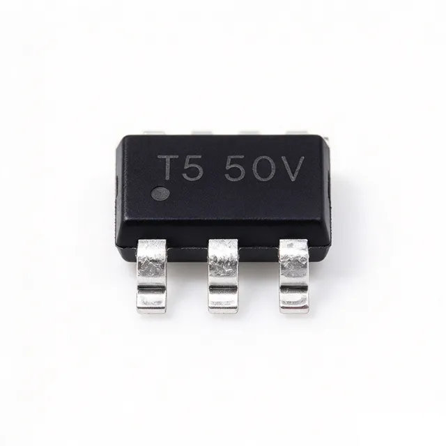
AP63205WU-7 - 32V, 2A Sync Buck Converter, TSOT-23-6 | Diodes Inc
MPN: AP63205WU-7 ✓ Active| Qty | Unit Price | Extended |
|---|---|---|
| 1 | $0.72 | $0.72 |
| 10 | $0.62 | $6.20 |
| 100 | $0.45 | $45.00 |
| 500 | $0.36 | $180.00 |
| 1,000 | $0.29 | $290.00 |
| 3,000 | $0.2036 | $610.80 |
AP63205WU-7 Overview
A buck converter (also called a step-down switching regulator) is a switched-mode power supply topology that converts a higher DC input voltage to a lower DC output voltage using an inductor, a switch, and a rectifier. Within the broader power-management IC hierarchy, the buck converter belongs to the DC-DC converter family, which is a sub-category of voltage regulators and, ultimately, power management semiconductors. Synchronous versions replace the external Schottky diode with an integrated low-side MOSFET to improve efficiency, especially at light loads and at high step-down ratios.
Key features include 22 µA ultralow quiescent current, 0.8 V ±1 % internal reference voltage, PWM control regardless of load, cycle-by-cycle peak current limit, and hiccup-mode overload protection. The AP63205 also incorporates proprietary EMI-mitigation techniques (frequency spread-spectrum or controlled switching-edge shaping) that simplify system compliance with CISPR 25 / EN 55022 in noise-sensitive consumer, industrial, and infotainment applications.
Typical applications include 12 V to 5 V point-of-load (POL) conversion for set-top boxes, white goods, eMMC storage rails, distributed 24 V industrial-bus subsystems, USB Type-C / HDMI supply rails, always-on housekeeping supplies, and aftermarket automotive infotainment modules. The TSOT-23-6 footprint and 1.1 MHz switching frequency make it well suited for space-constrained designs that require small inductors and a clean 5 V rail.
When designing with the AP63205WU-7, place the input capacitor as close as possible to the VIN and GND pins, keep the feedback trace short to minimize noise pickup, and verify that the chosen inductor saturation current exceeds the device's 2 A peak current-limit threshold. For battery-powered systems, the 22 µA Iq keeps standby drain low, but always include a bootstrap capacitor to ensure the high-side gate drive stays charged.
This page synthesizes XAIPART distributor pricing, drop-in alternatives (AP63203WU-7, AP63200WU-7), comparison parameters, and practical design notes not found in the manufacturer datasheet alone.
Drop-in alternatives for AP63205WU-7 — same package, pin-to-pin compatible. Different-package parts requiring PCB rework are excluded.
Variants in this series
Same-series models that are drop-in compatible with AP63205WU-7 (same form factor and footprint) — differing in Package, Output Voltage Range, Quiescent Current, Continuous Output Current, High-Side MOSFET Rds(on).
Quick Comparison Tool — Select alternative parts for side-by-side comparison:
AP63203WU-7
✓ In Stock
$0.32 / Unit
View Datasheet →AP63200WU-7
✓ In Stock
$0.49 / Unit
View Datasheet →AP63201WU-7
✓ In Stock
$0.45 / Unit
View Datasheet →TPS62150A-Q1
✓ In Stock
$1.85 / Unit
View Datasheet →TPS62130RGTR
✓ In Stock
$1.72 / Unit
View Datasheet →LMR16030SDDA
📋 Reference alternative (not in catalog)
AP63205WU-7 Maximum Ratings & Electrical Characteristics
| Topology | Synchronous Buck (Step-Down) |
| Input Voltage Range | 3.8 V to 32 V |
| Output Voltage | Fixed 5 V |
| Continuous Output Current | 2 A |
| Switching Frequency | 1.1 MHz |
| High-Side MOSFET Rds(on) | 125 mΩ |
| Low-Side MOSFET Rds(on) | 68 mΩ |
| Quiescent Current | 22 µA |
| Internal Reference Voltage | 0.8 V ±1 % |
| Control Method | PWM (regardless of load) |
| Protection Features | Cycle-by-cycle peak current limit, hiccup-mode overload protection |
| Operating Temperature Range | -40 °C to +85 °C (TA) |
| Package | TSOT-23-6 (TSOT26) |
| Mounting Type | Surface Mount |
| Light-Load Efficiency | Up to 80 % at 1 mA; up to 88 % at 5 mA |
AP63205WU-7 Pin Configuration
| Pin 1 | EN — Enable input (active high) |
| Pin 2 | GND — Ground reference |
| Pin 3 | SW — Switch node (connects to inductor) |
| Pin 4 | VIN — Input supply voltage (3.8 V to 32 V) |
| Pin 5 | BST — Bootstrap capacitor node for high-side gate drive |
| Pin 6 | NC — No connect on fixed 5 V output variant |
Typical Applications
AP63205WU-7 is suitable for 7 applications: 12 V to 5 V Point-of-Load (POL) Conversion, Set-Top Box and Streaming Device Power Rails, 24 V Industrial Bus Distributed Power, USB Type-C and HDMI 5 V Power Rails, Aftermarket Automotive Infotainment Modules, White Goods and Home Appliance Control Boards, IoT Gateway Always-On Housekeeping Supply.
12 V to 5 V Point-of-Load (POL) Conversion
The AP63205WU-7 is purpose-built for 12 V-to-5 V point-of-load conversion in space-constrained systems. With its 3.8-32 V input range and fixed 5 V output, it accepts a 12 V bus directly without an upstream pre-regulator, and the 1.1 MHz switching frequency allows a 2.2-4.7 µH inductor small enough to fit beneath the IC. The 2 A continuous output current drives downstream MCUs, eMMC memory, and USB-PHY rails simultaneously. Unlike larger SOIC-8 buck converters, the TSOT-23-6 footprint saves roughly 70 % board area while delivering equivalent thermal performance with proper copper pouring, making it the dominant choice for consumer set-top boxes and white-goods control boards.
Recommended
Set-Top Box and Streaming Device Power Rails
The AP63205WU-7 supplies the 5 V rail for SoCs, eMMC storage, and HDMI interfaces in set-top boxes and streaming devices. Its 22 µA quiescent current keeps standby power below 100 mW for Energy Star and EU Ecodesign compliance, and its proprietary EMI-mitigation circuitry simplifies passing CISPR 25 / EN 55022 conducted emissions on the first board spin. The 1.1 MHz switching frequency stays above the AM broadcast band, reducing input-filter complexity. Designers pair it with a 4.7 µH shielded inductor and 22 µF ceramic input/output capacitors for a complete sub-50 mm² solution that fits inside the plastic enclosure thermal envelope.
Recommended
24 V Industrial Bus Distributed Power
The AP63205WU-7 operates directly from a 24 V industrial bus (with transients to 32 V) to deliver a local 5 V rail for sensors, isolated transceivers, and MCU subsystems on distributed I/O modules. Its wide 3.8-32 V input eliminates the need for a separate pre-regulator, and the hiccup-mode overload protection prevents damage from output short circuits common in industrial wiring faults. The TSOT-23-6 footprint allows placement adjacent to each isolated channel on the PCB, reducing ground-loop area and improving noise immunity. Designers should add a TVS diode at the input for IEC 61000-4-2/4-4 transient protection on field-wired terminals.
Recommended
USB Type-C and HDMI 5 V Power Rails
The AP63205WU-7 provides the 5 V VBUS supply rail for USB Type-C downstream-facing ports and HDMI source-side interfaces, where a clean 5 V ±5 % rail is required to meet USB-IF and HDMI compliance masks. Its 2 A continuous output current supports USB BC 1.2 and Type-C 1.5 A/3 A current advertisement depending on detection scheme, and the 22 µA Iq enables always-on VBUS-present detection logic. The fixed 5 V output eliminates feedback-resistor tolerance errors that could otherwise push VBUS outside specification at high load. Designers typically add a load-switch downstream for port power switching and OVP protection.
Recommended
Aftermarket Automotive Infotainment Modules
The AP63205WU-7 powers the 5 V rail in aftermarket automotive infotainment modules that connect to a 12 V vehicle bus with cold-crank and load-dump transients. The 3.8-32 V input range survives 12 V crank dips down to ~4 V and 24 V jump-start events to 32 V without protective circuitry. The integrated 125 mΩ / 68 mΩ MOSFETs and PWM-only control provide predictable EMI performance across the automotive temperature range (-40 °C to +85 °C TA). Designers should add a reverse-battery protection diode and an input TVS clamp for ISO 7637-2 pulse immunity, and select an inductor with low DCR and adequate saturation current for the 2 A peak limit.
Recommended
White Goods and Home Appliance Control Boards
The AP63205WU-7 is widely used in white-goods control boards (washing machines, refrigerators, dishwashers) to derive a clean 5 V rail from the rectified 12 V or 24 V appliance bus. Its 22 µA Iq keeps standby power below the EU 2019/2022 eco-regulation standby limits (< 0.5 W for many appliances), and the TSOT-23-6 footprint fits within the tight control-board enclosures of modern appliances. The hiccup-mode overload protection prevents fire hazards during motor-stall or sensor-short faults. Its operating temperature range of -40 °C to +85 °C covers garage and outdoor-adjacent installations, and the 1.1 MHz switching frequency stays clear of AM-band interference that could affect adjacent RF receivers.
Recommended
IoT Gateway Always-On Housekeeping Supply
The AP63205WU-7 provides an always-on 5 V housekeeping supply in IoT gateways and smart-home hubs, where it powers the real-time clock, Wi-Fi/BLE module sleep rail, and tamper-detection sensors while the main system is off. Its 22 µA quiescent current enables multi-year battery operation for the always-on domain, and the 3.8-32 V input accepts a wide range of battery and bus voltages from single-cell Li-ion to 24 V industrial sources. Designers typically combine it with a higher-current buck (e.g., 3-5 A) for the main SoC rail, using the AP63205WU-7 specifically for the low-power housekeeping domain where efficiency at < 1 mA matters most.
Recommended
Recommended Products Summary
Engineering reference data for AP63205WU-7 — comparison, design guidance, and compliance information.
Selection Guide
Comparison with Alternatives
| Parameter | This Product | AP63203WU-7 | AP63200WU-7 | AP63201WU-7 | TPS62150A-Q1 | TPS62130RGTR | LMR16030SDDA |
|---|---|---|---|---|---|---|---|
| Package | TSOT-23-6 (TSOT26) | TSOT-23-6 (TSOT26) | TSOT-23-6 (TSOT26) | TSOT-23-6 (TSOT26) | TSOT-23-6 (TSOT26) | TSOT-23-6 (TSOT26) | TSOT-23-6 (TSOT26) |
| Brand | Diodes Incorporated | Diodes Incorporated | Diodes Incorporated | Diodes Incorporated | Texas Instruments | Texas Instruments | Texas Instruments |
| Input Voltage Range | 3.8 V to 32 V | 3.8 V to 32 V | 3.8 V to 32 V | 3.8 V to 32 V | 3 V to 17 V (narrower upper) | 3 V to 17 V (narrower upper) | 4 V to 60 V (wider upper) |
| Output Voltage | Fixed 5 V | Fixed 5 V | Adjustable | Adjustable | Adjustable | Adjustable | Adjustable |
| Continuous Output Current | 2 A | 2 A | 2 A | 2 A | 1 A (-50%) | 3 A (+50%) | 3 A (+50%) |
| Switching Frequency | 1.1 MHz | 1.1 MHz | 500 kHz | 500 kHz | 1.25 MHz | 1.25 MHz | 200 kHz to 2.5 MHz adj. |
| Light-Load Control Method | PWM (constant) | PWM (constant) | PWM (constant) | PFM (variable frequency) | PFM/PWM auto | PFM/PWM auto | PWM (constant) |
| Enhanced EMI Mitigation | Yes (proprietary) | No | No | No | No (but low-EMI design) | No | No |
Key Differentiators
- Enhanced EMI-mitigation circuitry integrated (vs AP63203WU-7)
- Higher switching frequency for smaller magnetics (vs AP63200WU-7)
- Constant-frequency PWM regardless of load (vs AP63201WU-7)
- Fixed 5 V output eliminates feedback divider (vs TPS62150A-Q1)
Design Notes
Place the input ceramic capacitor (10-22 µF X7R, 50 V rating) as close as possible to the VIN and GND pins, with traces no longer than 2 mm to minimize switching-node ringing. The SW node carries high di/dt; use a short, wide trace to the inductor and keep the feedback trace away from the SW/BST traces to avoid noise coupling. A small RC snubber (2.2 Ω + 1 nF) across the SW node may be required if the layout forces long SW traces. The BST capacitor (typically 0.1 µF) must be placed within 1 mm of the BST and SW pins to ensure proper high-side gate drive.
Verify that the chosen inductor saturation current (Isat) exceeds the AP63205WU-7's 2 A peak current-limit threshold; many 2.2 µH inductors saturate at 1.5-1.8 A and will cause early current-limit tripping under load transients. Also confirm DCR is below 50 mΩ to minimize conduction loss and prevent thermal runaway at high VIN. For battery-powered applications, the 22 µA Iq only applies in non-switching standby; during PWM operation the input current is dominated by the load.
Estimated: at VIN=12 V, VOUT=5 V, IOUT=2 A, the AP63205WU-7 dissipates approximately (12-5)*2 = 14 W, but realistic continuous duty-cycle losses (including switching loss and low-side conduction) drop the figure to roughly 0.7-0.9 W. With a TSOT-23-6 thermal resistance of approximately 70 °C/W on a 1 oz copper 4-layer board, the junction temperature rise is roughly 50-65 °C above ambient, requiring derating above 70 °C ambient. Increase copper pour area or add thermal vias beneath the exposed GND pad to maintain safe operation.
The AP63205WU-7's proprietary EMI-mitigation (spread-spectrum or controlled switching-edge shaping) reduces peak EMI by 5-10 dBµV compared to the AP63203WU-7, per the Diodes datasheet. For first-pass CISPR 25 / EN 55022 compliance, use a π-filter (10 µF + ferrite bead + 10 µF) at the input and keep the input-trace loop area under 25 mm². The 1.1 MHz fundamental and its harmonics fall in the FM broadcast band; an LC input filter tuned to ~50 MHz helps attenuate conducted emissions in this band.
Compliance Information
RoHS and REACH compliance per Diodes product page. Halogen-free per Diodes product family datasheet. Not AEC-Q100 qualified - for automotive-grade equivalent, check AP63205QWU-7 or similar -Q1 suffix variants.





