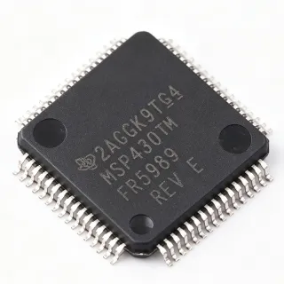
F280023PMSR - C2000 32-bit MCU, 100MHz, 64KB Flash, 64-LQFP | Texas Instruments
MPN: F280023PMSR ✓ Active| Qty | Unit Price | Extended |
|---|---|---|
| 1 | $4.5 | $4.50 |
| 10 | $4.05 | $40.50 |
| 100 | $3.6 | $360.00 |
| 500 | $3.2 | $1,600.00 |
| 1,000 | $2.85 | $2,850.00 |
F280023PMSR Overview
A C2000 microcontroller is a 32-bit MCU family engineered specifically for real-time control. In the broader taxonomy, the F280023PMSR sits as: microcontroller -> embedded MCU -> 32-bit MCU -> real-time control MCU -> C2000 family -> F28002x sub-family. Unlike general-purpose MCUs that prioritize connectivity or low power, C2000 devices focus on deterministic interrupt latency and high-resolution PWM generation, which are foundational for digital control of switches, motors, and power converters.
Key features include the 100 MHz C28x core with hardware FPU/TMU for single-cycle trigonometric math, 64 KB flash, integrated control peripherals (ePWM, eCAP, eQEP), analog comparators and ADCs, plus InstaSPIN-FOC library compatibility. The device's FPU/TMU offloads math-intensive routines such as Park/Clarke transforms, freeing the CPU for application logic. The 64-LQFP package offers generous GPIO and a generous PCB thermal pad footprint for cost-sensitive designs.
Architecturally, the F28002x combines the legacy C28x DSP-style core with a C28x+CLA-style bus matrix and a tightly-coupled control-law accelerator option in higher SKUs. The FPU executes single-precision IEEE-754 arithmetic in hardware, while the TMU accelerates sin, cos, arctan, and square-root operations used in field-oriented control (FOC) firmware.
Typical applications include solar inverters, industrial motor drives (BLDC/PMSM), digital power supplies, traction inverters, and LED lighting drivers. The integrated PWM and ADC peripherals make it a strong fit for any closed-loop digital control system that demands deterministic sub-microsecond response.
When designing with this part, ensure your linker script reserves the correct flash wait-state configuration for 100 MHz operation, and review the boot-ROM GPIO multiplexing table before laying out the PCB. This page synthesizes distributor pricing, same-family F28002x drop-in alternatives, and practical design notes not found in the manufacturer datasheet alone.
Drop-in alternatives for F280023PMSR — same package, pin-to-pin compatible. Different-package parts requiring PCB rework are excluded.
Variants in this series
Same-series models that are drop-in compatible with F280023PMSR (same form factor and footprint) — differing in Core Architecture, Package.
Quick Comparison Tool — Select alternative parts for side-by-side comparison:
F280023PMQR
✅ Drop-In📋 Reference alternative (not in catalog)
F280023PMS
✅ Drop-In📋 Reference alternative (not in catalog)
F280024PMSR
✅ Drop-In📋 Reference alternative (not in catalog)
F280025PMSR
✅ Drop-In📋 Reference alternative (not in catalog)
F280027PMSR
✅ Drop-In📋 Reference alternative (not in catalog)
F280023PMSRQ1
✅ Drop-In📋 Reference alternative (not in catalog)
F280023PMSR Maximum Ratings & Electrical Characteristics
| Core Architecture | C28x 32-bit with FPU and TMU |
| CPU Speed | 100 MHz |
| Flash Memory | 64 KB (32K x 16) |
| Package | 64-LQFP (PM) 10x10 mm |
| Pin Count | 64 |
| Operating Temperature Range | -40°C to 125°C (junction, S grade) |
| Mounting Type | Surface Mount |
| RoHS Status | Compliant |
| Series | C2000™ F28002x |
| Lead-Free | Yes |
| Reel Packaging Suffix | R (Tape and Reel) |
| Product Family | TMS320F28002x Real-Time Microcontrollers |
F280023PMSR Pin Configuration
| Pin 1 | GPIO0 — General-purpose I/O / ePWM1A output |
| Pin 2 | GPIO1 — General-purpose I/O / ePWM1B output |
| Pin 3 | GPIO2 — General-purpose I/O / ePWM2A output |
| Pin 4 | GPIO3 — General-purpose I/O / ePWM2B output |
| Pin 5 | GPIO4 — General-purpose I/O / ePWM3A output |
| Pin 6 | GPIO5 — General-purpose I/O / ePWM3B output |
| Pin 7 | GPIO6 — General-purpose I/O / ePWM4A output |
| Pin 8 | GPIO7 — General-purpose I/O / ePWM4B output |
| Pin 9 | GPIO8 — General-purpose I/O / ePWM5A output |
| Pin 10 | GPIO9 — General-purpose I/O / ePWM5B output |
| Pin 11 | GPIO10 — General-purpose I/O / ePWM6A output |
| Pin 12 | GPIO11 — General-purpose I/O / ePWM6B output |
| Pin 13 | GPIO12 — General-purpose I/O / TZ1 input |
| Pin 14 | GPIO13 — General-purpose I/O / TZ2 input |
| Pin 15 | GPIO14 — General-purpose I/O / TZ3 input |
| Pin 16 | GPIO15 — General-purpose I/O / XCLKOUT output |
| Pin 17 | GPIO16 — General-purpose I/O / SPISTEA / CANRXA |
| Pin 18 | GPIO17 — General-purpose I/O / SPISOMIA / CANTXA |
| Pin 19 | GPIO18 — General-purpose I/O / SPICLKA |
| Pin 20 | GPIO19 — General-purpose I/O / SPISTEA |
| Pin 21 | VDD — Digital supply voltage (3.3V) |
| Pin 22 | VSS — Digital ground reference |
| Pin 23 | GPIO20 — General-purpose I/O / eQEP1A input |
| Pin 24 | GPIO21 — General-purpose I/O / eQEP1B input |
| Pin 25 | GPIO22 — General-purpose I/O / eQEP1S input |
| Pin 26 | GPIO23 — General-purpose I/O / eQEP1I input |
| Pin 27 | GPIO24 — General-purpose I/O / ECAP1 input/output |
| Pin 28 | GPIO25 — General-purpose I/O / ECAP2 input/output |
| Pin 29 | GPIO26 — General-purpose I/O / ECAP3 input/output |
| Pin 30 | GPIO27 — General-purpose I/O / HRCAP1 input |
| Pin 31 | GPIO28 — General-purpose I/O / SCIA_RX / I2CA_SDA |
| Pin 32 | GPIO29 — General-purpose I/O / SCIA_TX / I2CA_SCL |
| Pin 33 | GPIO30 — General-purpose I/O / CANRXB |
| Pin 34 | GPIO31 — General-purpose I/O / CANTXB |
| Pin 35 | VDDIO — Digital I/O supply voltage |
| Pin 36 | VDDA — Analog supply voltage (3.3V) |
| Pin 37 | VSSA — Analog ground reference |
| Pin 38 | ADCINB0 — ADC-B Channel 0 input |
| Pin 39 | ADCINB1 — ADC-B Channel 1 input |
| Pin 40 | ADCINB2 — ADC-B Channel 2 input |
| Pin 41 | ADCINB3 — ADC-B Channel 3 input |
| Pin 42 | ADCINA0 — ADC-A Channel 0 input |
| Pin 43 | ADCINA1 — ADC-A Channel 1 input |
| Pin 44 | ADCINA2 — ADC-A Channel 2 input |
| Pin 45 | ADCINA3 — ADC-A Channel 3 input |
| Pin 46 | ADCINA4 — ADC-A Channel 4 input |
| Pin 47 | ADCINA5 — ADC-A Channel 5 input |
| Pin 48 | VREFHIA — ADC-A high reference voltage |
| Pin 49 | VREFLOA — ADC-A low reference voltage |
| Pin 50 | VREFHIB — ADC-B high reference voltage |
| Pin 51 | VREFLOB — ADC-B low reference voltage |
| Pin 52 | VDD — Digital supply voltage (1.2V core) |
| Pin 53 | VSS — Digital ground |
| Pin 54 | XRS — Reset input (active low) |
| Pin 55 | X1 — Crystal oscillator input |
| Pin 56 | X2 — Crystal oscillator output |
| Pin 57 | TEST — Test mode pin (recommend connect to VDD) |
| Pin 58 | VDD — Digital supply voltage |
| Pin 59 | VSS — Digital ground |
| Pin 60 | GPIO32 — General-purpose I/O / SDAA |
| Pin 61 | GPIO33 — General-purpose I/O / SCLA |
| Pin 62 | GPIO34 — General-purpose I/O |
| Pin 63 | GPIO35 — General-purpose I/O |
| Pin 64 | GPIO37 — General-purpose I/O / TZ4 input |
Typical Applications
F280023PMSR is suitable for 7 applications: Solar Inverter MPPT and DC-AC Control, BLDC / PMSM Motor Drive (Field-Oriented Control), Digital Switch-Mode Power Supply (SMPS) Control, Industrial Servo Drive and Robotics, EV Traction Inverter Sub-Controller (Auxiliary), LED Lighting Drivers and Digital Ballasts, Uninterruptible Power Supply (UPS) Control.
Solar Inverter MPPT and DC-AC Control
The F280023PMSR's 100 MHz C28x core with FPU and TMU executes MPPT algorithms and inverter control loops in real time, making it well-suited for single-phase solar inverters up to 5 kW. The integrated ePWM channels drive the IGBT/MOSFET gate signals at 20-100 kHz switching frequency with sub-microsecond duty-cycle resolution, while the 64 KB flash stores the inverter control state machine, MPPT lookup tables, and grid-synchronization firmware. The -40°C to 125°C junction temperature range supports outdoor inverter enclosures without derating. Compared to general-purpose MCUs, the FPU/TMU accelerates Park/Clarke transforms used in grid-tie inverter control loops, freeing CPU cycles for protection logic and grid-code compliance checks.
Recommended
BLDC / PMSM Motor Drive (Field-Oriented Control)
The F280023PMSR is purpose-built for single-axis BLDC and PMSM motor drives using field-oriented control (FOC). The hardware TMU executes sin/cos/arithmetic in single cycles, dramatically reducing the computational load of Park/Clarke transforms in the FOC current loop running at 10-20 kHz. The 64 KB flash holds the FOC state machine, PI controller coefficients, and protection routines for sensored or sensorless BLDC drives up to 1 HP. The integrated eQEP peripheral interfaces directly with quadrature encoders, while ePWM outputs generate the complementary 3-phase gate signals with programmable dead-band insertion.
Recommended
Digital Switch-Mode Power Supply (SMPS) Control
The F280023PMSR enables digital control of switch-mode power supplies including totem-pole PFC, LLC resonant converters, and phase-shifted full-bridge topologies. The high-resolution ePWM type-4 peripherals generate center-aligned or edge-aligned PWMs with 150 ps resolution at 100 MHz, critical for soft-switching and valley-skipping control. The 64 KB flash stores the digital compensator firmware, while the integrated ADC samples output voltage and current at the PWM switching frequency for multi-loop digital control. The FPU accelerates digital filter math for cycle-by-cycle current mode control without CPU saturation.
Recommended
Industrial Servo Drive and Robotics
For industrial servo drives, robotic joint controllers, and CNC spindle control, the F280023PMSR provides deterministic real-time response essential for multi-axis synchronization. The C28x deterministic interrupt latency ensures the FOC current loop completes within the 50-100 µs control period without jitter, critical for high-bandwidth position control. The integrated eQEP decoders handle incremental encoder inputs from servo motors, while CAN-FD peripherals enable multi-axis coordination across distributed servo networks. The 64-LQFP package exposes sufficient GPIO for limit-switch inputs, brake control, and fault-flag monitoring typical in industrial servo designs.
Recommended
EV Traction Inverter Sub-Controller (Auxiliary)
The F280023PMSR serves as an auxiliary controller in EV powertrains managing DC-DC converters, onboard chargers, and traction inverter auxiliary functions. The AEC-Q100 variant (F280023PMSRQ1) is qualified for under-hood automotive environments. The 100 MHz C28x+FPU+TMU executes interleaved multi-phase DC-DC control loops, while the CAN-FD peripherals interface with the vehicle's central VCU. The -40°C to 125°C junction rating handles under-hood thermal loads, and the 64-LQFP footprint enables compact PCB designs in space-constrained automotive power electronics modules.
Recommended
LED Lighting Drivers and Digital Ballasts
The F280023PMSR provides intelligent control for commercial LED drivers, digital ballasts, and horticultural lighting systems. The ePWM peripherals drive PFC + LLC converter stages with precise dimming control via analog or DALI interfaces. The 64 KB flash stores dimming curves, thermal foldback algorithms, and adaptive brightness firmware. The integrated ADC samples LED current and temperature for closed-loop brightness and thermal protection. Compared to analog ballast ICs, the F280023PMSR enables programmable dimming profiles and remote control via UART or CAN without external ballast control ICs.
Recommended
Uninterruptible Power Supply (UPS) Control
The F280023PMSR's real-time control capability makes it ideal for online UPS systems managing inverter switching, battery charging, and grid synchronization. The FPU/TMU accelerates grid-synchronization PLL algorithms and inverter current control loops running at 20 kHz switching frequency. The 64 KB flash stores the inverter state machine, battery management firmware, and LCD interface logic. The -40°C to 125°C junction temperature supports UPS installations in unconditioned electrical rooms. Drop-in compatibility with F280025PMSR allows field upgrades for higher-power three-phase UPS systems.
Recommended
Recommended Products Summary
Engineering reference data for F280023PMSR — comparison, design guidance, and compliance information.
Selection Guide
Comparison with Alternatives
| Parameter | This Product | F280023PMQR | F280024PMSR | F280025PMSR | F280027PMSR | F280023PMSRQ1 |
|---|---|---|---|---|---|---|
| Package | 64-LQFP (PM) 10x10 mm | 64-LQFP (PM) - same | 64-LQFP (PM) - same | 64-LQFP (PM) - same | 64-LQFP (PM) - same | 64-LQFP (PM) - same |
| Brand | Texas Instruments | Texas Instruments | Texas Instruments | Texas Instruments | Texas Instruments | Texas Instruments |
| Flash Memory | 64 KB | 64 KB (same) | 32 KB (-50%) | 128 KB (+100%) | 256 KB (+300%) | 64 KB (same) |
| CPU Speed | 100 MHz | 100 MHz (same) | 100 MHz (same) | 100 MHz (same) | 100 MHz (same) | 100 MHz (same) |
| Temperature Grade | S (-40°C to 125°C TJ) | Q (-40°C to 125°C TJ) | S (same) | S (same) | S (same) | Q automotive (-40°C to 125°C, AEC-Q100) |
| Packaging Format | Tape & Reel (R suffix) | Tape & Reel | Tape & Reel | Tape & Reel | Tape & Reel | Tape & Reel |
| Automotive Qualified | No | No | No | No | No | Yes (AEC-Q100) |
| Approximate Unit Price (1k qty) | $2.85-$3.20 | Similar | Lower (~$2.50) | Higher (+30-40%) | Higher (+60-80%) | Higher (automotive premium) |
Key Differentiators
- Cost-optimized mid-density F28002x SKU (vs F280025PMSR (128 KB flash))
- Automotive-grade upgrade path available (vs F280023PMSR (standard grade))
- Pin-to-pin scalable within F28002x family (vs F280027PMSR (256 KB flash))
Design Notes
Estimated: At 100 MHz CPU utilization with typical C2000 control loop workload (ePWM + ADC + FOC math), the F280023PMSR dissipates approximately 0.3-0.5 W. With 64-LQFP thermal resistance theta_JA of approximately 50-60 °C/W on a 4-layer JEDEC PCB, junction temperature rise is 15-30 °C above ambient. The -40°C to 125°C junction rating provides ample headroom for industrial enclosures. For elevated temperature environments, recommend 1 oz copper pours on top/bottom layers connected to VSS and at least 4 thermal vias under the exposed lead frame pad area for additional heat spreading.
Place the 1.2 µF bulk capacitor within 5 mm of the VDD pin and the 0.1 µF decoupling capacitor as close as possible (<3 mm) to each VDD/VSS pair. For ADC analog inputs, route ADCINA/ADCINB traces with a ground reference plane underneath and avoid routing digital signals (ePWM, GPIO) parallel to analog traces for at least 3x the trace width. Place the 10 MHz or 20 MHz crystal within 5 mm of X1/X2 pins with short, symmetric traces and guard ring ground pour. Use separate analog (VDDA/VSSA) and digital (VDDIO) supply ferrite beads to isolate switching noise from ADC references.
Do not skip configuring flash wait states in the application startup code - at 100 MHz CPU clock, the F280023PMSR requires 3 wait states to access 64 KB flash within the access timing budget. Forgetting wait states causes instruction fetch corruption and erratic firmware execution. Verify the boot-mode GPIO pins (GPIO24/GPIO32) are configured correctly before power-up or the device will not enter the intended boot mode. When migrating from F280025/F280027 firmware, update linker command files to reflect the 64 KB flash memory map and adjust the code placement for the smaller flash region.
Route ePWM output traces with controlled impedance (typically 50 Ω) and keep traces under 50 mm to minimize ringing on gate-driver outputs. For motor-drive applications, keep the ePWM and gate-driver traces away from ADC current-sense traces to prevent capacitive coupling of switching noise into analog measurements. Place ground stitching vias every 5-10 mm along ePWM trace edges and along the perimeter of the LQFP package. Use a 4-layer PCB stack-up with continuous ground plane on layer 2 beneath the MCU for best EMC and signal-integrity performance in motor-drive applications.
Compliance Information
RoHS and REACH compliant per TI product page. Not AEC-Q100 qualified in this MPN - choose F280023PMSRQ1 for automotive applications. Lead-free packaging confirmed.