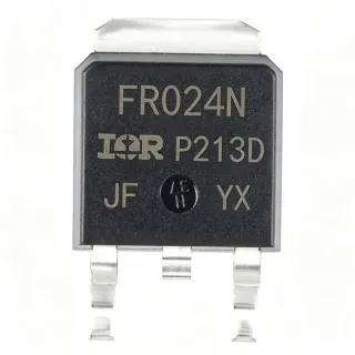
IRFR220NPBF - 200V N-Channel HEXFET MOSFET, 5A | Infineon
MPN: IRFR220NPBF ✓ Active| Qty | Unit Price | Extended |
|---|---|---|
| 1 | $1.34 | $1.34 |
| 10 | $1.18 | $11.80 |
| 100 | $0.99 | $99.00 |
| 500 | $0.85 | $425.00 |
| 1,000 | $0.74 | $740.00 |
Drop-in alternatives for IRFR220NPBF — same package, pin-to-pin compatible. Different-package parts requiring PCB rework are excluded.
Quick Comparison Tool — Select alternative parts for side-by-side comparison:
IRFR220NTRLPBF
✅ Drop-In✓ In Stock
$0.22 / Unit
View Datasheet →IRFR220NTRRPBF
✅ Drop-In📋 Reference alternative (not in catalog)
IRFR4620TRLPBF
✅ Drop-In✓ In Stock
$1.72 / Unit
View Datasheet →IRFR4620PBF
✅ Drop-In📋 Reference alternative (not in catalog)
IRFZ24NPBF
✅ Drop-In ⚠️ 参数待验证✓ In Stock
$0.46 / Unit
View Datasheet →IRFR2405TRPBF
✅ Drop-In✓ In Stock
$0.61 / Unit
View Datasheet →IRFR2405TRLPBF
✅ Drop-In✓ In Stock
$0.55 / Unit
View Datasheet →IRFR220NPBF Maximum Ratings & Electrical Characteristics
| FET Type | N-Channel MOSFET, Metal Oxide |
| Drain-to-Source Voltage (VDS) | 200 V |
| Continuous Drain Current (ID) at TC=25C | 5 A |
| Power Dissipation (PD) at TC=25C | 43 W |
| Static Drain-Source On-Resistance (RDS(on)) max | 0.6 ohm at VGS = 10 V |
| Mounting Type | Surface Mount |
| Package / Case | TO-252AA (DPAK) |
| Technology | HEXFET (Planar) |
| Operating Temperature Range | -55C to +150C (junction) |
| Lead-Free / RoHS | Yes, lead-free (PBF suffix) |
| Avalanche Energy Rated | Yes (per datasheet characterization) |
| Pin Count | 3 (Gate, Drain, Source) plus tab |
| MSL Level | 1 (per JEDEC J-STD-020) |
IRFR220NPBF Pin Configuration
| Pin 1 | Gate — Gate control input - drive to 10V for full enhancement |
| Pin 2 | Drain — Drain terminal (also bonded to metal tab) - load current input |
| Pin 3 | Source — Source terminal - return path for drain current |
| Pin Tab | Drain — Metal tab electrically connected to Drain (pin 2); primary thermal path |
IRFR220NPBF Maximum Safe Operating Area (DC)
Typical Applications
IRFR220NPBF is suitable for 6 applications: High-Frequency DC-DC Converters, Switch-Mode Power Supplies (SMPS), Motor Drive Low-Side Switch, Solenoid and Relay Drivers, General-Purpose Power Switching, Inductive Heating and Snubber Circuits.
High-Frequency DC-DC Converters
The IRFR220NPBF is well suited for hard-switched and resonant DC-DC converter stages thanks to its fully characterized output capacitance (Coss) and low gate-to-drain charge. The 200 V drain rating covers 120 V rectified bus operation with derating headroom, and the 5 A continuous current handles sub-100 W converter outputs. Placed on the low-side switch of a buck or the primary switch of a flyback, it minimizes switching loss at 100-500 kHz while keeping conduction loss manageable at moderate loads.
Recommended
Switch-Mode Power Supplies (SMPS)
In offline and DC-fed SMPS front ends, the IRFR220NPBF serves as the primary-side MOSFET or as a secondary-side synchronous-rectifier-style switch in low-power isolated converters. The 200 V rating supports 100-130 V AC rectified inputs (after PFC or directly in non-PFC designs). Its planar HEXFET technology trades a higher RDS(on) for excellent avalanche ruggedness, which simplifies snubber design and absorbs energy from leakage-inductance spikes in flyback and forward converters.
Recommended
Motor Drive Low-Side Switch
The IRFR220NPBF can be used as a low-side switch in brushed DC motor drivers up to 5 A continuous, suitable for small fans, pumps, and actuators operating on 24-48 V rails. The 200 V VDS rating far exceeds typical low-voltage motor bus voltages, providing ample transient headroom for inductive kickback. Designers should add a flyback diode or use the body diode and ensure PWM frequencies stay below the thermal time constant of the DPAK package.
Recommended
Solenoid and Relay Drivers
Industrial solenoid valves, relays, and latch coils are well-served by the IRFR220NPBF as a low-side driver. The 5 A continuous rating handles most 24 V solenoid coils directly, and the 200 V VDS absorbs the inductive flyback spike when the coil de-energizes (with an external freewheeling diode recommended for hot switching). The DPAK package provides enough thermal mass for intermittent high-current pulses that exceed the steady-state rating.
Recommended
General-Purpose Power Switching
For generic load-switching, lamp drivers, and battery-protection circuits below 200 V, the IRFR220NPBF offers a robust surface-mount solution. The HEXFET technology has a long track record in industrial designs and is supported by Infineon's extensive characterization, including SOA curves and transient thermal impedance. When used as a high-side switch, a gate-drive bootstrap or charge pump is required because the source is not at ground.
Recommended
Inductive Heating and Snubber Circuits
The IRFR220NPBF is avalanche-rated and can absorb energy from inductive switching transients, making it usable in snubber discharge paths and small induction-heater topologies. Per the Infineon datasheet, the device is 100% avalanche-tested, so engineers can rely on the specified EAS rating during single-pulse unclamped inductive switching events. Mounting the DPAK tab to a sufficient copper pour is essential to keep junction temperature within the 150 C maximum during repetitive avalanche events.
Recommended
Recommended Products Summary
Engineering reference data for IRFR220NPBF — comparison, design guidance, and compliance information.
Selection Guide
Comparison with Alternatives
| Parameter | This Product | IRFR220NTRLPBF | IRFR220NTRRPBF | IRFR4620TRLPBF | IRFR4620PBF | IRFZ24NPBF | IRFR2405TRPBF |
|---|---|---|---|---|---|---|---|
| Package | TO-252AA (DPAK) | TO-252AA (DPAK) - same | TO-252AA (DPAK) - same | TO-252AA (DPAK) - same | TO-252AA (DPAK) - same | TO-252AA (DPAK) - same | TO-252AA (DPAK) - same |
| Brand | Infineon | Infineon | Infineon | Infineon | Infineon | Infineon | Infineon |
| VDS (Drain-Source Voltage) | 200 V | 200 V | 200 V | 200 V | 200 V | 55 V | 55 V |
| Continuous Drain Current (ID) | 5 A | 5 A | 5 A | 48 A | 48 A | 17 A | 56 A |
| RDS(on) max at VGS=10V | 0.6 ohm | 0.6 ohm | 0.6 ohm | 0.026 ohm | 0.026 ohm | 0.07 ohm | 0.045 ohm |
| Technology | HEXFET (Planar) | HEXFET (Planar) | HEXFET (Planar) | Trench | Trench | HEXFET (Planar) | HEXFET (Planar) |
| Power Dissipation (PD) at TC=25C | 43 W | 43 W | 43 W | 144 W | 144 W | 45 W | 70 W |
| Lead-Free / RoHS | Yes (PBF suffix) | Yes (PBF suffix) | Yes (PBF suffix) | Yes (PBF suffix) | Yes (PBF suffix) | Yes (PBF suffix) | Yes (PBF suffix) |
Key Differentiators
- Mature planar HEXFET technology with proven long-term reliability (vs IRFR4620PBF)
- 200V voltage rating in compact DPAK footprint (vs IRFZ24NPBF)
- Standard industry reference part with broad distributor availability (vs IRFR220N (legacy, non-Pb-free))
Design Notes
The DPAK package dissipates 43 W only when the case is held at 25 C - in a real PCB without a heatsink, the actual continuous dissipation is limited by RthJA (typically 50-80 C/W depending on copper area). Estimated: with 1 square inch of 2 oz copper on a 4-layer FR-4 board, RthJA is about 40 C/W. At 5 A continuous with 0.6 ohm RDS(on), conduction loss alone is 15 W, yielding a junction temperature rise of 600 C above ambient - clearly impossible. Practical continuous current without a heatsink is 1-2 A maximum. Add an external heatsink or much larger copper pour (4+ square inches) to approach the datasheet rating.
Solder the DPAK tab directly to a copper pour that extends through multiple thermal vias to the bottom layer and opposite-side copper. The tab is electrically connected to the drain, so the copper pad also serves as the drain connection. For high-current paths, use 2 oz or 3 oz copper on the drain layer and stitch vias every 2-3 mm around the tab perimeter to maximize heat transfer. Avoid placing the gate trace parallel to the drain copper to minimize capacitive coupling that can cause unwanted turn-on.
Do not exceed VGS = +/- 20 V absolute maximum - the gate oxide is fragile and will rupture if overdriven. When using a gate driver, add a 10 kohm pull-down resistor from gate to source to ensure the MOSFET stays off during controller power-up or transient glitches. For high-side (source-floating) switching, a bootstrap or charge-pump driver is required because the source voltage rises with the switch node. The IRFR220NPBF's body diode is relatively slow - for synchronous-rectifier applications above 100 kHz, consider an external fast-recovery diode or a Trench MOSFET.
Keep the gate-drive loop as small as possible: place the gate resistor and pull-down resistor within 5 mm of the gate pin, and route the gate trace on the opposite side of the PCB from the drain copper to minimize parasitic capacitance. The drain-source current loop (input cap to MOSFET drain to load to ground back to input cap) should also be minimized to reduce ringing and EMI. For switching frequencies above 200 kHz, add a small RC snubber (10 ohm + 1 nF) across drain-source if ringing exceeds 20% of VDS.
Compliance Information
PBF suffix confirms lead-free / RoHS compliant per Infineon product page. Halogen-free per MSL1 rating and Infineon datasheet. Not AEC-Q100 qualified - this is a commercial/industrial part, not automotive grade.