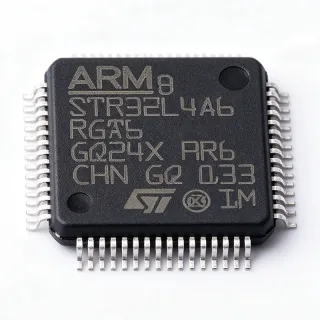
MSPM0L2227-Q1 - Automotive Cortex-M0+ MCU | Texas Instruments
MPN: MSPM0L2227-Q1 ✓ Active| Qty | Unit Price | Extended |
|---|---|---|
| 1 | $4.95 | $4.95 |
| 10 | $4.45 | $44.50 |
| 100 | $3.75 | $375.00 |
| 500 | $3.2 | $1,600.00 |
| 1,000 | $2.85 | $2,850.00 |
Drop-in alternatives for MSPM0L2227-Q1 — same package, pin-to-pin compatible. Different-package parts requiring PCB rework are excluded.
Quick Comparison Tool — Select alternative parts for side-by-side comparison:
MSPM0L2228-Q1
✅ Drop-In✓ In Stock
Contact for price
View Datasheet →MSPM0L1227-Q1
✅ Drop-In📋 Reference alternative (not in catalog)
MSPM0L2227
✅ Drop-In📋 Reference alternative (not in catalog)
MSPM0L1305-Q1
✅ Drop-In✓ In Stock
$1.85 / Unit
View Datasheet →MSPM0L2227-Q1 Maximum Ratings & Electrical Characteristics
| Core Processor | ARM Cortex-M0+ |
| Core Size | 32-Bit |
| Speed | 32 MHz |
| Program Memory Size | 128 KB (128K x 8) |
| Program Memory Type | Dual-bank Flash |
| RAM Size | 32 KB |
| Number of I/O | 59 |
| ADC Channels | 26 (12-bit) |
| LCD Segments | 59 pins, multiple mux/bias configurations |
| Package | 64-LQFP (10x10 mm) |
| Operating Temperature | -40°C to +125°C (AEC-Q100) |
| Voltage - Supply (Vcc/Vdd) | [DATA_NEEDED: supply voltage range] |
| Mounting Type | Surface Mount |
| RoHS Status | Compliant |
| Automotive Grade | AEC-Q100 Qualified |
| Peripherals | LCD, IWDT, RTC, UART, SPI, I2C, DMA, Timers, Analog Comparator |
MSPM0L2227-Q1 Pin Configuration
| Pin 1 | VDD — Digital supply voltage |
| Pin 17 | VSS — Ground |
| Pin 32 | PA0 — Port A, Pin 0 (GPIO/ADC) |
| Pin 33 | PA1 — Port A, Pin 1 (GPIO/ADC) |
| Pin 48 | PB0 — Port B, Pin 0 (GPIO) |
| Pin 49 | PB1 — Port B, Pin 1 (GPIO) |
| Pin 64 | RST — Reset input |
Safe Operating Area (SOA) & Thermal Characteristics
No official SOA curve available for this digital IC. Always operate within absolute maximum ratings specified in the datasheet. Ensure adequate cooling and derate as needed.
Typical Applications
MSPM0L2227-Q1 is suitable for 6 applications: Automotive Body Control Module, LCD Instrument Cluster, Battery-Powered IoT Sensors, HVAC Control Panel, Infotainment System Interface, Secure Access Control.
Automotive Body Control Module
The MSPM0L2227-Q1's 32 MHz Cortex-M0+ core, 128 KB dual-bank flash, and AEC-Q100 qualification make it ideal for body control modules requiring reliable operation across -40°C to +125°C. Its integrated 12-bit ADC monitors analog sensors, while UART/SPI/I2C interfaces communicate with other ECUs. The low-power architecture reduces current consumption when the vehicle is parked, and the backup power island maintains RTC and tamper detection.
Recommended
LCD Instrument Cluster
The integrated segmented LCD controller with up to 59 pins drives instrument cluster glass directly, reducing system cost and PCB area. The MSPM0L2227-Q1 can multiplex up to 8 COM lines and 51 segment lines, supporting a wide range of display configurations. Its 32 MHz core handles real-time gauge updates, while dual-bank flash enables over-the-air firmware updates. The low-power modes preserve display content during ignition-off.
Recommended
Battery-Powered IoT Sensors
The MSPM0L2227-Q1's ultra-low-power design, including multiple sleep modes, extends battery life in remote sensors. The 32 KB SRAM buffers sensor samples, while the 12-bit ADC digitizes analog inputs. An integrated comparator can wake the MCU from sleep on threshold crossing, ideal for door and temperature sensors in smart buildings. The RTC and tamper I/O enable secure time-stamping for event logging.
Recommended
HVAC Control Panel
Automotive HVAC panels need MCUs with integrated LCD support, which the MSPM0L2227-Q1 provides. The 32 MHz core handles fan speed control, temperature sensing, and button debouncing. Multiple UART and I2C interfaces connect to blower motor drivers and climate sensors. Its automotive qualification ensures reliable operation under temperature extremes and vibration, while the AEC-Q100 compliance meets OEM requirements.
Recommended
Infotainment System Interface
The MSPM0L2227-Q1 provides a low-power interface bridge in infotainment systems, controlling LEDs, buttons, and rotary encoders. Its multiple I2C and UART channels handle communication with audio codecs and touch controllers. The 128 KB flash stores UI firmware, while dual-bank allows background updates. The LCD controller can directly drive segmented displays, reducing the need for external display drivers.
Recommended
Secure Access Control
The backup power island on the MSPM0L2227-Q1, with independent RTC, IWDT, 32-byte memory, and tamper I/O, makes it well-suited for secure access control systems. The tamper detection lines trigger an alarm if the enclosure is opened, while the RTC logs event times. The integrated comparator can monitor battery voltage for tamper evidence, and the low-power mode maintains security in battery-operated locks.
Recommended
Recommended Products Summary
Engineering reference data for MSPM0L2227-Q1 — comparison, design guidance, and compliance information.
Selection Guide
Comparison with Alternatives
| Parameter | This Product | MSPM0L2228-Q1 | MSPM0L1227-Q1 | MSPM0L2227 |
|---|---|---|---|---|
| Package | 64-LQFP (10x10 mm) | 64-LQFP (10x10 mm) - same | 64-LQFP (10x10 mm) - same | 64-LQFP (10x10 mm) - same |
| Brand | Texas Instruments | Texas Instruments | Texas Instruments | Texas Instruments |
| Core | ARM Cortex-M0+ | ARM Cortex-M0+ | ARM Cortex-M0+ | ARM Cortex-M0+ |
| Flash Memory | 128 KB | 128 KB | 64 KB | 128 KB |
| SRAM | 32 KB | 32 KB | 32 KB | 32 KB |
| LCD Controller | Yes, up to 59 pins | Yes, more segments | Yes, up to 59 pins | Yes, up to 59 pins |
| ADC Resolution | 12-bit | 12-bit | 12-bit | 12-bit |
| Automotive Qualified | Yes (AEC-Q100) | Yes (AEC-Q100) | Yes (AEC-Q100) | No |
Key Differentiators
- Drop-in automotive-qualified variant (vs MSPM0L2227)
- Integrated LCD controller with up to 59 pins (vs MSPM0L1306-Q1)
- 128 KB dual-bank flash (vs MSPM0L1227-Q1)
Design Notes
The MSPM0L2227-Q1 operates from a [DATA_NEEDED: VDD range]. Add appropriate decoupling capacitors (0.1 uF and 10 uF) close to the VDD pins, and connect the VDDA pin to a clean analog supply with a ferrite bead for stable ADC conversions.
Follow TI's recommended layout for the 64-LQFP package. Use a solid ground plane under the MCU, route high-speed signals away from the crystal oscillator, and place the crystal and load capacitors as close as possible to the XIN and XOUT pins for reliable 32 MHz operation.
Ensure the RST pin is not floating; tie it to VDD via a pull-up resistor or a supervisor. The dual-bank flash allows read-while-write, but avoid simultaneous writes to the same bank. Use the internal reset controller and watchdog to recover from software lock-ups.
Compliance Information
Per TI product page, AEC-Q100 qualified. RoHS status per distributors. REACH and halogen-free status not stated in provided data.