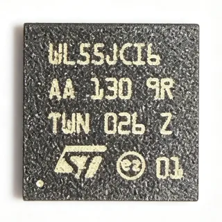
NRF51822QFAC - Bluetooth LE/2.4GHz SoC, 256kB Flash | Nordic
MPN: NRF51822QFAC ✗ End of Life| Qty | Unit Price | Extended |
|---|---|---|
| 1 | $6.4 | $6.40 |
| 10 | $5.92 | $59.20 |
| 100 | $5.2 | $520.00 |
| 500 | $4.55 | $2,275.00 |
| 1,000 | $3.95 | $3,950.00 |
NRF51822QFAC Overview
An RF System-on-Chip (SoC) is a single silicon die that combines a microcontroller core, on-chip program and data memory, analog/RF peripherals, and a radio transceiver. The nRF51822 belongs to the Bluetooth SoC family (Bluetooth low energy SoC -> wireless MCU -> connected microcontroller -> general-purpose MCU), which is itself a branch of the broader category of short-range wireless ICs. By collapsing the MCU and radio into one die, an RF SoC dramatically shrinks PCB area, simplifies BOM, and lowers sleep current compared with two-chip MCU+transceiver designs - enabling coin-cell-powered products that can run for years on a single CR2032.
Key features include a Cortex-M0 core running up to 16 MHz (31.25 MHz when using the on-chip HFCL), 256 kB on-chip flash for application + softdevice storage, 32 kB on-chip SRAM, a flexible 2.4 GHz radio supporting Bluetooth low energy (v4.0) and Nordic Gazell proprietary modes, integrated balun, and a rich set of peripherals including 10-bit ADC, RTC, GPIO, I2C, SPI, UART, and PWM. The QFN-48 (6x6 mm) package exposes an EP that must be soldered to the board ground for thermal and RF performance.
Typical applications include BLE beacons, fitness bands, smart watches, medical sensor patches, remote controls, smart-home bridges, and industrial telemetry nodes. The combination of sub-uA sleep current and on-chip Cortex-M0 processing makes it well suited to products where battery life is measured in months rather than hours.
When laying out a board, observe Nordic's reference layout: route the differential RF port (RFIO P0.18 / RFIO1 P0.21 on QFACA) with controlled 50 ohm impedance, place the chip's exposed pad on a continuous ground pour, and keep decoupling capacitors within 2 mm of the supply pins. The radio's TX output power, RX sensitivity, and blocking performance all depend on this layout.
This page synthesizes distributor pricing, drop-in QFN-48 alternatives from the Nordic nRF51/nRF52 family, and PCB-level design notes that are not collected in any single manufacturer document.
Drop-in alternatives for NRF51822QFAC — same package, pin-to-pin compatible. Different-package parts requiring PCB rework are excluded.
Quick Comparison Tool — Select alternative parts for side-by-side comparison:
NRF51822QFAC-R
✅ Drop-In📋 Reference alternative (not in catalog)
NRF51822QFAC-T
✅ Drop-In📋 Reference alternative (not in catalog)
NRF51822QFAA-R
✅ Drop-In📋 Reference alternative (not in catalog)
NRF51422QFAC
✅ Drop-In📋 Reference alternative (not in catalog)
NRF52832QFAA
✅ Drop-In📋 Reference alternative (not in catalog)
NRF51822QFAC Maximum Ratings & Electrical Characteristics
| Product Type | Bluetooth Low Energy / 2.4 GHz SoC |
| Core | ARM Cortex-M0 |
| Core Clock | 16 MHz (HFCL 31.25 MHz available) |
| Flash | 256 kB |
| RAM | 32 kB |
| Radio | 2.4 GHz Bluetooth v4.0 + proprietary (Gazell) |
| Package | 48-pin QFN (6 x 6 mm) with exposed pad (QFN-48 / 48-VFQFN-EP) |
| Mounting Type | Surface Mount |
| Peripherals | 10-bit ADC, RTC, I2C, SPI, UART, PWM, AES |
| Protocol Stack | Bluetooth low energy (v4.0), 2.4 GHz Gazell |
| RoHS Status | Compliant |
| Lead-Free | Yes |
NRF51822QFAC Pin Configuration
| Pin 1 | VDD — Power supply input |
| Pin 2 | GND — Ground |
| Pin 3 | DEC1 — Decoupling pin |
| Pin 4 | DEC2 — Decoupling pin |
| Pin 5 | DEC3 — Decoupling pin |
| Pin 6 | DEC4 — Decoupling pin |
| Pin 7 | VDDH — High-voltage supply (radio) |
| Pin 8 | VDD_PA — Power amplifier supply |
| Pin 9 | ANT — Differential antenna port (P0.18 / ANT1) |
| Pin 10 | ANT2 — Differential antenna port (P0.21 / ANT2) |
| Pin 11 | GND — Ground |
| Pin 12 | RESET — Reset pin (active low) |
| Pin 13 | SWDIO — Serial Wire Debug I/O |
| Pin 14 | SWDCLK — Serial Wire Debug clock |
| Pin 15 | GPIO — General purpose I/O |
| Pin 16 | GPIO — General purpose I/O |
| Pin 17 | GPIO — General purpose I/O |
| Pin 18 | GPIO — General purpose I/O |
| Pin 19 | GPIO — General purpose I/O |
| Pin 20 | GPIO — General purpose I/O |
| Pin 21 | GPIO — General purpose I/O |
| Pin 22 | GPIO — General purpose I/O |
| Pin 23 | GPIO — General purpose I/O |
| Pin 24 | GPIO — General purpose I/O |
| Pin 25 | GPIO — General purpose I/O |
| Pin 26 | GPIO — General purpose I/O |
| Pin 27 | GPIO — General purpose I/O |
| Pin 28 | GPIO — General purpose I/O |
| Pin 29 | GPIO — General purpose I/O |
| Pin 30 | GPIO — General purpose I/O |
| Pin 31 | GPIO — General purpose I/O |
| Pin 32 | GPIO — General purpose I/O |
| Pin 33 | GPIO — General purpose I/O |
| Pin 34 | GPIO — General purpose I/O |
| Pin 35 | GPIO — General purpose I/O |
| Pin 36 | GPIO — General purpose I/O |
| Pin 37 | GPIO — General purpose I/O |
| Pin 38 | GPIO — General purpose I/O |
| Pin 39 | GPIO — General purpose I/O |
| Pin 40 | GPIO — General purpose I/O |
| Pin 41 | GPIO — General purpose I/O |
| Pin 42 | GPIO — General purpose I/O |
| Pin 43 | DEC5 — Decoupling pin |
| Pin 44 | DEC6 — Decoupling pin |
| Pin 45 | VDD — Power supply input |
| Pin 46 | GND — Ground |
| Pin 47 | GND — Ground |
| Pin 48 | GND — Ground |
Typical Applications
NRF51822QFAC is suitable for 7 applications: Bluetooth Low Energy Beacons, Fitness Bands and Wearables, Medical Sensor Patches, Smart Home Hubs and Bridges, Industrial Wireless Sensor Nodes, BLE-Enabled Remote Controls, Wireless PC Peripherals (Mice/Keyboards).
Bluetooth Low Energy Beacons
The NRF51822QFAC's 256 kB flash comfortably fits Eddystone or iBeacon firmware alongside the BLE softdevice, while its sub-microamp sleep current lets coin-cell-powered beacons advertise for 1-3 years on a single CR2032. Place the chip with its exposed pad soldered to a continuous ground pour to preserve the radio link budget - the QFN-48 footprint is small enough to fit inside a 25 mm diameter puck-style beacon enclosure.
Recommended
Fitness Bands and Wearables
With Cortex-M0 DSP plus BLE v4.0, the NRF51822QFAC can drive a fitness band's accelerometer, heart-rate sensor, and OLED display while streaming data to a smartphone over BLE. The 256 kB flash and 32 kB RAM are sufficient for typical wearable application code. The QFN-48 6x6 mm footprint fits inside a 15 mm x 40 mm band module, and the BLE link enables real-time heart-rate broadcast and firmware updates over the air (DFU).
Recommended
Medical Sensor Patches
Medical patch designs leverage the NRF51822QFAC's ultra-low sleep current and Cortex-M0 processing to drive continuous glucose, temperature, or ECG monitoring from a 3V coin cell. The integrated AES hardware accelerator enables secure BLE communication required for HIPAA-conscious medical data transfer. Use an external LDO like the LP5900TLX-1.8 to clean the supply for low-noise analog front-end measurements.
Recommended
Smart Home Hubs and Bridges
In a smart-home bridge, the NRF51822QFAC's BLE radio and Cortex-M0 can act as a gateway between BLE sensors and a Wi-Fi/Ethernet host. The 256 kB flash supports the BLE softdevice plus a Gazell proprietary bridge protocol for legacy 2.4 GHz sensors. The QFN-48 footprint is small enough to embed inside a wall-switch module, and Nordic's Gazell star network lets the hub pair with up to 8000 sensor nodes.
Recommended
Industrial Wireless Sensor Nodes
Industrial sensor nodes benefit from the NRF51822QFAC's industrial temperature range and robust 2.4 GHz radio. Combined with Modbus-over-BLE firmware, the chip can wirelessly expose factory sensor data to a tablet or gateway. The exposed-pad QFN-48 package is suitable for conformal-coated industrial boards, and Nordic's OTA DFU capability allows remote firmware updates across thousands of deployed nodes.
Recommended
BLE-Enabled Remote Controls
TV set-top boxes, smart speakers, and BLE remote controls use the NRF51822QFAC for voice command relay, BLE pairing, and IR-over-BLE bridges. Its 256 kB flash supports rich HID profiles plus voice codec buffering. Pair it with a low-power audio ADC and a haptic driver to create a full-featured BLE remote that runs for over a year on two AAA batteries thanks to the chip's low sleep current.
Recommended
Wireless PC Peripherals (Mice/Keyboards)
The NRF51822QFAC's BLE v4.0 radio and 2.4 GHz proprietary mode are widely used in low-latency wireless mice, keyboards, and game controllers. Nordic's Gazell mode offers sub-5 ms latency suitable for gaming mice, while BLE enables universal smartphone pairing. The chip's high GPIO count drives a 16-bit RGB LED matrix and a high-resolution scroll-wheel sensor simultaneously.
Recommended
Recommended Products Summary
Engineering reference data for NRF51822QFAC — comparison, design guidance, and compliance information.
Selection Guide
Comparison with Alternatives
| Parameter | This Product | NRF51822QFAC-R | NRF51822QFAC-T | NRF51822QFAA-R | NRF51422QFAC | NRF52832QFAA |
|---|---|---|---|---|---|---|
| Brand | Nordic Semiconductor | Nordic Semiconductor | Nordic Semiconductor | Nordic Semiconductor | Nordic Semiconductor | Nordic Semiconductor |
| Package | QFN-48 (6x6 mm) | QFN-48 (6x6 mm) - same | QFN-48 (6x6 mm) - same | QFN-48 (6x6 mm) - same | QFN-48 (6x6 mm) - same | QFN-48 (6x6 mm) - same |
| Core | ARM Cortex-M0 | ARM Cortex-M0 | ARM Cortex-M0 | ARM Cortex-M0 | ARM Cortex-M0 | ARM Cortex-M3A |
| Flash | 256 kB | 256 kB | 256 kB | 128 kB | 256 kB | 512 kB |
| RAM | 32 kB | 32 kB | 32 kB | 16 kB | 32 kB | 64 kB |
| Bluetooth Version | v4.0 BLE | v4.0 BLE | v4.0 BLE | v4.0 BLE | v4.0 BLE + ANT+ | Bluetooth 5 |
| ANT+ Support | No | No | No | No | Yes | No |
| Lifecycle Status | NRND | NRND | NRND | NRND | NRND | Active |
Key Differentiators
- Highest on-chip memory in nRF51822 family (vs NRF51822QFAA-R)
- Lower-power Cortex-M0 vs newer Cortex-M3A core (vs NRF52832QFAA)
- Pin-compatible upgrade path to active-production nRF52832 (vs NRF52832QFAA)
Design Notes
Route the differential RF port (ANT/ANT2 on the QFN-48 QFAC build) with a controlled 50 ohm differential impedance. Nordic's reference layout shows a 0.5 mm trace width on 0.2 mm spacing over a 4-layer FR4 stackup. The exposed pad (EP) must be soldered to a continuous ground plane with at least 8 thermal vias - omitting the EP ground connection degrades radio range and causes RF instability.
Decouple each VDD/VDDH pin with a 100 nF ceramic capacitor placed within 2 mm of the pin. Add a 10 uF bulk capacitor near the radio section to absorb TX load transients (peak current ~12 mA at 0 dBm). A separate LP5029 ferrite bead between the digital and RF supplies reduces conducted noise coupling into the ADC readings.
Do not assume the QFAC variant has the same pinout as QFAA builds across all GPIO assignments - several pin functions (e.g. RESET, SWDIO) move between QFAC/QFAA revisions. Always cross-reference the exact pin name table in the nRF51822 datasheet before PCB layout. Failing to do so results in non-functional boards that pass initial power-up but fail firmware download.
At maximum continuous TX output (0 dBm), the QFN-48 die dissipates roughly 30 mW. With the EP soldered to a 1 square inch copper pour on a 4-layer board, theta_JA is around 35 C/W, yielding a 1 C temperature rise above ambient - acceptable. Without the EP ground, junction temperature can rise 10-15 C, risking CW transmission failures above 25 C ambient.
Compliance Information
RoHS and REACH compliant per Nordic product page. Not AEC-Q100 qualified - this part is intended for consumer/commercial/industrial wireless products, not automotive. Conflict-minerals declaration available from Nordic.