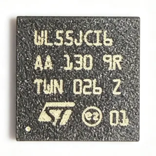
RTL8201F - 10/100M Ethernet PHYceiver, MII/RMII | Realtek
MPN: RTL8201F ✓ Active| Qty | Unit Price | Extended |
|---|---|---|
| 1 | $1.2 | $1.20 |
| 10 | $1.05 | $10.50 |
| 100 | $0.85 | $85.00 |
| 500 | $0.7 | $350.00 |
| 1,000 | $0.55 | $550.00 |
| 3,000 | $0.42 | $1,260.00 |
RTL8201F Overview
An Ethernet PHYceiver (Physical Layer Transceiver) is the analog/digital mixed-signal interface between the MAC (Media Access Controller) and the physical copper/fiber medium. It performs line coding/decoding, echo/Next cancellation, baseline wander correction, and signal detection. The PHY category sits within the broader networking IC hierarchy: Ethernet PHY -> Network Interface -> Communication IC -> Semiconductor. The RTL8201F integrates both PHY and transceiver functions, eliminating the need for an external transformer-coupled analog front end in many designs.
Key features of the RTL8201F include auto MDIX (automatic crossover correction), auto-negotiation for 10/100 Mbps speed and full/half duplex, hardware configuration via strap pins or MDIO/MII management register access, and support for both MII (Media Independent Interface) and RMII (Reduced Media Independent Interface) MAC-side connections. The device supports 25 MHz external crystal or clock input and includes built-in termination resistors for the differential transmit and receive pairs. It implements HP Auto-MDIX for automatic TX/RX pair swap.
Technically, the RTL8201F uses mixed-signal processing for adaptive equalization, data recovery, and error correction across CAT5 twisted-pair cable up to 100m. The internal architecture includes a DSP-based echo canceller, AGC, PLL, and MLT-3 encoder/decoder. Power consumption is managed through several low-power states including a power-down mode. The device supports both 3.3V analog and 1.8V or 3.3V digital supplies via internal regulators.
Typical applications of the RTL8201F include embedded Ethernet in industrial automation controllers, IoT gateways, IP cameras, smart home hubs, network printers, and consumer networking equipment. It is the standard low-cost PHY used in microcontroller-based designs with built-in Ethernet MAC (such as STM32, ESP32, NXP i.MX RT series) requiring a single-port 10/100 Mbps copper interface.
Design considerations: Route the MII/RMII bus with impedance-controlled traces and keep length-matched within the MAC timing budget. Place the 25 MHz crystal within 5mm of the RTL8201F XI/XO pins. Use a 1:1 transformer (e.g., Hanrun HR601680E) on the network side. Decouple AVDD with a 10uF + 0.1uF pair per pin, and DVDD with 0.1uF at each pin.
This page synthesizes distributor pricing, drop-in alternatives, and practical PCB design notes for the RTL8201F that are not consolidated on the manufacturer datasheet alone, helping engineers select and implement this PHY with confidence.
Drop-in alternatives for RTL8201F — same package, pin-to-pin compatible. Different-package parts requiring PCB rework are excluded.
Quick Comparison Tool — Select alternative parts for side-by-side comparison:
RTL8201FI-VC-CG
✅ Drop-In📋 Reference alternative (not in catalog)
RTL8201F-VB-CG
✅ Drop-In📋 Reference alternative (not in catalog)
SZ18201
✅ Drop-In📋 Reference alternative (not in catalog)
RTL8201FL
✅ Drop-In ⚠️ Specs Unverified📋 Reference alternative (not in catalog)
RTL8201FN
✅ Drop-In ⚠️ Specs Unverified📋 Reference alternative (not in catalog)
LAN8720A
✅ Drop-In📋 Reference alternative (not in catalog)
DP83825
✅ Drop-In📋 Reference alternative (not in catalog)
RTL8201F Specifications
| Product Type | 10/100M Ethernet PHYceiver (PHY + Transceiver) |
| Data Rate | 10 Mbps / 100 Mbps |
| Network Standard | IEEE 802.3, 802.3u (10BASE-T, 100BASE-TX) |
| MAC Interface | MII / RMII |
| Management Interface | MDIO (Clause 22) |
| Supply Voltage (Analog) | 3.3 V |
| Supply Voltage (Digital) | 3.3 V or 1.8 V |
| Auto-MDIX | Yes (HP Auto-MDIX) |
| Auto-Negotiation | Yes (speed and duplex) |
| Fiber Interface | PECL interface for 100Base-FX |
| Package | 32-pin QFN EP (5x5 mm) |
| Operating Temperature | 0°C to +70°C (commercial) |
| Mounting Type | Surface Mount |
| MSL Level | 3 (per JEDEC J-STD-020) |
| RoHS Status | Compliant (VB-CG suffix) |
| Lead-Free | Yes |
| Crystal Frequency | 25 MHz |
RTL8201F Pin Configuration
| Pin 1 | RXN — Differential receive pair (negative) |
| Pin 2 | RXP — Differential receive pair (positive) |
| Pin 3 | AVDD — Analog 3.3V supply |
| Pin 4 | TXN — Differential transmit pair (negative) |
| Pin 5 | TXP — Differential transmit pair (positive) |
| Pin 6 | AVDD — Analog 3.3V supply |
| Pin 7 | AGND — Analog ground |
| Pin 8 | XI — 25 MHz crystal input |
| Pin 9 | XO — 25 MHz crystal output |
| Pin 10 | AGND — Analog ground |
| Pin 11 | RST — Hardware reset (active low) |
| Pin 12 | MDC — Management data clock |
| Pin 13 | MDIO — Management data I/O |
| Pin 14 | RXD0/MODE0 — MII RX data bit 0 / strap mode 0 |
| Pin 15 | RXD1/MODE1 — MII RX data bit 1 / strap mode 1 |
| Pin 16 | DVDD — Digital 3.3V or 1.8V supply |
| Pin 17 | RXDV/CRSDV — MII RX data valid / RMII carrier sense and data valid |
| Pin 18 | RXER/RXER — MII RX error |
| Pin 19 | RXC/REF_CLK — MII RX clock / RMII 50 MHz reference |
| Pin 20 | DGND — Digital ground |
| Pin 21 | TXC — MII TX clock |
| Pin 22 | TXEN/TXEN — MII/RMII transmit enable |
| Pin 23 | TXD0/TXD0 — MII/RMII TX data bit 0 |
| Pin 24 | TXD1/TXD1 — MII/RMII TX data bit 1 |
| Pin 25 | CRS — Carrier sense |
| Pin 26 | COL — Collision detect |
| Pin 27 | LED0 — Link/activity LED indicator |
| Pin 28 | LED1 — Speed LED indicator |
| Pin 29 | DVDD — Digital 3.3V or 1.8V supply |
| Pin 30 | DGND — Digital ground |
| Pin 31 | NC — Not connected (per datasheet) |
| Pin 32 | NC — Not connected (per datasheet) |
| Pin 33 | EP — Exposed thermal pad - connect to AGND |
Typical Applications
RTL8201F is suitable for 6 applications: MCU-Based Embedded Ethernet (STM32, NXP i.MX RT, ESP32), Industrial IoT Gateways and PLCs, IP Cameras and Surveillance Equipment, Smart Home Hubs and Consumer Networking, Network Printers and Multifunction Devices, Set-Top Boxes and Media Players.
MCU-Based Embedded Ethernet (STM32, NXP i.MX RT, ESP32)
The RTL8201F is the de facto standard PHY for microcontroller designs that include a built-in Ethernet MAC. Its 32-pin QFN EP (5x5 mm) footprint fits comfortably under a 1:1 transformer footprint, and its RMII interface uses just 9 MAC pins, leaving more GPIO for application use. With auto-MDIX and auto-negotiation, no manual configuration is needed at the RJ45 jack. Drivers for the RTL8201F are bundled with lwIP, FreeRTOS+TCP, and Linux netdev, making integration fast. Engineers should place a 25 MHz crystal within 5 mm of XI/XO and route RMII traces with matched length to meet the 50 MHz timing budget at the STM32 MAC pins.
Recommended
Industrial IoT Gateways and PLCs
The RTL8201F-VB-CG operates over 0°C to 70°C and supports 100 Mbps full-duplex with auto-MDIX, making it a low-cost PHY for industrial IoT gateways where the host MCU handles protocol conversion (Modbus TCP, EtherNet/IP, PROFINET). In PLC designs, the RTL8201F's PECL interface option enables 100Base-FX fiber connection for electrically noisy factory floors where copper is unreliable. Industrial designers should consider the industrial-grade RTL8201FI-VC-CG variant for -40°C to +85°C operation. Decoupling requires 10uF + 0.1uF pairs on each AVDD pin.
Recommended
IP Cameras and Surveillance Equipment
IP cameras require a low-power, small-footprint 10/100M PHY to feed the video encoder SoC. The RTL8201F's 32-pin QFN EP (5x5 mm) and low power-down current suit compact camera PCB layouts. Auto-MDIX simplifies installation by eliminating crossover cable concerns. The RMII interface at 50 MHz keeps the SoC-to-PHY bus pin count low, freeing board space for the image sensor and DRAM. The RTL8201F supports jumbo frame pass-through when paired with capable MACs, useful for high-resolution video streams.
Recommended
Smart Home Hubs and Consumer Networking
The RTL8201F's low unit cost (from $0.25 at LCSC as of 2026-10-15) and broad distributor availability make it the standard PHY for Wi-Fi router secondary Ethernet ports, smart home hubs, and consumer gateways. Its auto-negotiation and auto-MDIX deliver plug-and-play behavior expected in consumer products. The RTL8201F integrates well with Realtek's own Wi-Fi chipsets, sharing reference designs and validation collateral. For Matter/Thread border routers and Home Assistant hubs, the RTL8201F provides the wired Ethernet uplink reliably.
Recommended
Network Printers and Multifunction Devices
Network printers and MFPs require a reliable, low-cost 10/100M PHY for the Ethernet management port. The RTL8201F's low power consumption and small footprint suit the compact controller board of an entry-level printer. Its MDIO Clause 22 register map allows the printer SoC to query link status for status page display. Auto-MDIX eliminates crossover cable issues in mixed IT environments. The RTL8201F's wide operating temperature range (0°C to 70°C) handles the warm interior of a printer chassis.
Recommended
Set-Top Boxes and Media Players
Set-top boxes and Android TV devices need a wired Ethernet port for high-bandwidth video streaming. The RTL8201F delivers 100 Mbps full-duplex throughput suitable for 4K HDR streaming from a home network. The RMII interface keeps the SoC pin count low, and the small 5x5 mm QFN-32 footprint fits under the RJ45 jack with magnetics. Auto-negotiation with the home router/switch is transparent. The RTL8201F is widely used in Android TV boxes based on Amlogic and Rockchip SoCs.
Recommended
Recommended Products Summary
Engineering reference data for RTL8201F — comparison, design guidance, and compliance information.
Selection Guide
Comparison with Alternatives
| Parameter | This Product | RTL8201FI-VC-CG | RTL8201F-VB-CG | SZ18201 | LAN8720A | DP83825 |
|---|---|---|---|---|---|---|
| Brand | Realtek | Realtek | Realtek | Realtek (clone) | Microchip Technology | Texas Instruments |
| Package | 32-pin QFN EP (5x5 mm) | 32-pin QFN EP | 32-pin QFN EP | 32-pin QFN EP | 24-pin QFN (different footprint) | 32-pin QFN (different pinout) |
| Data Rate | 10/100 Mbps | 10/100 Mbps | 10/100 Mbps | 10/100 Mbps | 10/100 Mbps | 10/100 Mbps |
| MAC Interface | MII/RMII | MII/RMII | MII/RMII | MII/RMII | RMII only | MII/RMII/RGMII |
| Operating Temperature | 0°C to +70°C | -40°C to +85°C (industrial) | 0°C to +70°C | 0°C to +70°C (typical) | -40°C to +85°C | -40°C to +125°C (extended) |
| Auto-MDIX | Yes | Yes | Yes | Yes | Yes | Yes |
| Supply Voltage | 3.3V (analog/digital) | 3.3V | 3.3V | 3.3V | 3.3V (single supply) | 3.3V |
| Fiber Interface (100Base-FX) | Yes (PECL) | Yes | Yes | Yes | No | No |
Key Differentiators
- Integrated PECL interface for 100Base-FX fiber (vs LAN8720A)
- Lowest unit cost among standard 10/100 PHYs (vs DP83825 (TI))
- Widest MCU ecosystem driver support (vs SZ18201 (clone))
- Commercial temperature grade only in base part (vs RTL8201FI-VC-CG (industrial variant))
Design Notes
Place the 25 MHz crystal within 5 mm of the RTL8201F XI/XO pins with traces guarded by a ground pour. Route the MII/RMII bus with impedance-controlled 50 ohm traces (or per MAC SoC spec) and length-match TXC, RXC, TXD[1:0], RXD[1:0], TXEN, RXDV within the MAC timing budget. The differential transmit pair (TXP/TXN) and receive pair (RXP/RXN) must be routed as 100 ohm differential pairs and kept as short as possible. Place the 1:1 transformer (e.g., Hanrun HR601680E) immediately adjacent to the RJ45 jack. Decouple each AVDD with a 10uF bulk + 0.1uF ceramic pair; each DVDD with a 0.1uF ceramic.
Do not omit the management pull-up resistor on MDIO - it must be pulled to DVDD through 1.5 to 10 kohm depending on bus capacitance. Failing to strap MII/RMII mode correctly at reset results in undefined behavior. Do not exceed 100 Mbps cable distance; CAT5 cable is rated for 100m at 100BASE-TX. Ensure proper Bobbin-resistant ground to the magnetics center tap via a 0.1uF cap to the decoupling ground; failure here creates EMI issues. Always assert hardware reset (RST low then high) after power stabilization per datasheet timing.
The RTL8201F is a low-power PHY with typical 200mW dissipation during active 100BASE-TX operation. The 32-pin QFN EP package dissipates heat through the exposed pad; solder the EP to a grounded copper pour of at least 25 mm² for thermal relief. At maximum operating temperature (70°C commercial), no active cooling is required. Power-down mode drops consumption to <50 mW, suitable for energy-conscious IoT designs using the RTL8201F power-down pin.
Estimated: at 100 Mbps over CAT5 cable up to 100m, the RTL8201F's adaptive DSP equalizes the signal and recovers digital impairments with link margin typically >10 dB. For OEM designs, verify the eye diagram at the RJ45 with a scope probe - degraded eye opening indicates cable or magnetics issues. The 25 MHz reference clock drives both the internal PHY PLL and (in RMII mode) the MAC clock; this clock must meet ±50 ppm accuracy for proper 100BASE-TX operation. Excessive jitter (>200 ps p-p) on REF_CLK causes link drops.
Compliance Information
RoHS compliant per the VB-CG suffix designation. Not AEC-Q100 qualified - for automotive, consider automotive-grade Ethernet PHYs. Halogen-free and conflict minerals declarations not in provided data.