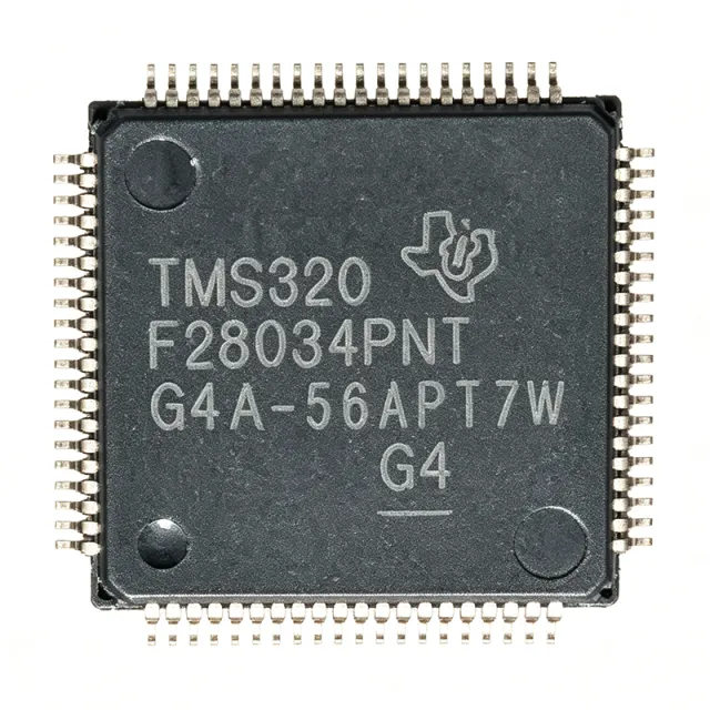
TMS320F28034PNT - 60MHz C2000 Piccolo MCU | Texas Instruments
MPN: TMS320F28034PNT ✓ Active| Qty | Unit Price | Extended |
|---|---|---|
| 1 | $8.5 | $8.50 |
| 10 | $7.8 | $78.00 |
| 100 | $6.9 | $690.00 |
| 500 | $6.2 | $3,100.00 |
| 1,000 | $5.6 | $5,600.00 |
TMS320F28034PNT Overview
A microcontroller (MCU) is a compact integrated circuit that combines a processor core, memory, and programmable input/output peripherals on a single chip. The C28x core is a 32-bit fixed-point DSP optimized for real-time control, offering high-speed math capabilities essential for closed-loop systems. The TMS320F28034PNT belongs to the C2000 family, which is specifically designed for applications requiring precise, deterministic control.
Key features include a 60 MHz C28x CPU, 128 KB flash, 20 KB RAM, a 12-bit ADC with up to 16 channels, and multiple communication interfaces such as SPI, SCI (UART), I2C, and CAN. The device also includes ePWM modules, eQEP, eCAP, and a watchdog timer. The Control Law Accelerator (CLA) is a co-processor that can execute control algorithms independently, freeing the main CPU for other tasks.
The TMS320F28034PNT operates from a 3.3V I/O supply with an internal 1.8V core, and supports a temperature range of -40°C to 105°C. It is code-compatible with other C28x devices, allowing software reuse across the family. The device is available in a lead-free, RoHS-compliant LQFP-80 package.
Typical applications include field-oriented control (FOC) of AC induction and BLDC motors, digital power supplies (e.g., LLC converters), solar inverters, and industrial drives. The high-performance ADC and PWM modules make it ideal for precise current and voltage sensing and control.
When designing with this MCU, ensure proper decoupling of the 3.3V and 1.8V supplies, and consider using the internal voltage regulator with external capacitors as specified in the datasheet. The JTAG interface is essential for debugging and programming, and should be routed with appropriate signal integrity.
Drop-in alternatives for TMS320F28034PNT — same package, pin-to-pin compatible. Different-package parts requiring PCB rework are excluded.
Variants in this series
Same-series models that are drop-in compatible with TMS320F28034PNT (same form factor and footprint) — differing in Package, Core, Flash Memory, Communication Interfaces, Supply Voltage.
Quick Comparison Tool — Select alternative parts for side-by-side comparison:
TMS320F28035PNT
✓ In Stock
Contact for price
View Datasheet →TMS320F28069UPNT
✓ In Stock
$8.1 / Unit
View Datasheet →TMS320F2808PZS
✓ In Stock
$8.32 / Unit
View Datasheet →TMS320F28032PNT
📋 Reference alternative (not in catalog)
TMS320F28033PNT
📋 Reference alternative (not in catalog)
TMS320F28034PNT Maximum Ratings & Electrical Characteristics
| Core | C28x 32-bit fixed-point DSP |
| Frequency | 60 MHz |
| Flash Memory | 128 KB (64K x 16) |
| RAM | 20 KB |
| ADC Resolution | 12-bit |
| ADC Channels | 16 |
| Supply Voltage | 3.3V I/O, 1.8V core |
| Operating Temperature | -40°C to 105°C |
| Package | 80-LQFP (12x12 mm) |
| Mounting Type | Surface Mount |
| Data Bus Width | 32-bit |
| Communication Interfaces | SPI, SCI (UART), I2C, CAN |
| PWM Modules | ePWM, eQEP, eCAP |
| Control Law Accelerator | Yes |
| RoHS Status | Compliant |
TMS320F28034PNT Pin Configuration
| Pin 1 | VDDIO — I/O supply voltage (3.3V) |
| Pin 2 | VSS — Ground |
| Pin 3 | X1 — Crystal oscillator input |
| Pin 4 | X2 — Crystal oscillator output |
| Pin 5 | VDD — Core supply voltage (1.8V) |
| Pin 6 | VSS — Ground |
| Pin 7 | GPIO0 — General purpose I/O |
| Pin 8 | GPIO1 — General purpose I/O |
| Pin 9 | GPIO2 — General purpose I/O |
| Pin 10 | GPIO3 — General purpose I/O |
| Pin 11 | GPIO4 — General purpose I/O |
| Pin 12 | GPIO5 — General purpose I/O |
| Pin 13 | GPIO6 — General purpose I/O |
| Pin 14 | GPIO7 — General purpose I/O |
| Pin 15 | GPIO8 — General purpose I/O |
| Pin 16 | GPIO9 — General purpose I/O |
| Pin 17 | GPIO10 — General purpose I/O |
| Pin 18 | GPIO11 — General purpose I/O |
| Pin 19 | GPIO12 — General purpose I/O |
| Pin 20 | GPIO13 — General purpose I/O |
| Pin 21 | GPIO14 — General purpose I/O |
| Pin 22 | GPIO15 — General purpose I/O |
| Pin 23 | GPIO16 — General purpose I/O |
| Pin 24 | GPIO17 — General purpose I/O |
| Pin 25 | GPIO18 — General purpose I/O |
| Pin 26 | GPIO19 — General purpose I/O |
| Pin 27 | GPIO20 — General purpose I/O |
| Pin 28 | GPIO21 — General purpose I/O |
| Pin 29 | GPIO22 — General purpose I/O |
| Pin 30 | GPIO23 — General purpose I/O |
| Pin 31 | GPIO24 — General purpose I/O |
| Pin 32 | GPIO25 — General purpose I/O |
| Pin 33 | GPIO26 — General purpose I/O |
| Pin 34 | GPIO27 — General purpose I/O |
| Pin 35 | GPIO28 — General purpose I/O |
| Pin 36 | GPIO29 — General purpose I/O |
| Pin 37 | GPIO30 — General purpose I/O |
| Pin 38 | GPIO31 — General purpose I/O |
| Pin 39 | VDDIO — I/O supply voltage (3.3V) |
| Pin 40 | VSS — Ground |
| Pin 41 | ADCINA0 — ADC input channel A0 |
| Pin 42 | ADCINA1 — ADC input channel A1 |
| Pin 43 | ADCINA2 — ADC input channel A2 |
| Pin 44 | ADCINA3 — ADC input channel A3 |
| Pin 45 | ADCINA4 — ADC input channel A4 |
| Pin 46 | ADCINA5 — ADC input channel A5 |
| Pin 47 | ADCINA6 — ADC input channel A6 |
| Pin 48 | ADCINA7 — ADC input channel A7 |
| Pin 49 | ADCINB0 — ADC input channel B0 |
| Pin 50 | ADCINB1 — ADC input channel B1 |
| Pin 51 | ADCINB2 — ADC input channel B2 |
| Pin 52 | ADCINB3 — ADC input channel B3 |
| Pin 53 | ADCINB4 — ADC input channel B4 |
| Pin 54 | ADCINB5 — ADC input channel B5 |
| Pin 55 | ADCINB6 — ADC input channel B6 |
| Pin 56 | ADCINB7 — ADC input channel B7 |
| Pin 57 | VREFLO — ADC low reference |
| Pin 58 | VREFHI — ADC high reference |
| Pin 59 | VDD — Core supply voltage (1.8V) |
| Pin 60 | VSS — Ground |
| Pin 61 | JTAG_TMS — JTAG test mode select |
| Pin 62 | JTAG_TDI — JTAG test data input |
| Pin 63 | JTAG_TDO — JTAG test data output |
| Pin 64 | JTAG_TCK — JTAG test clock |
| Pin 65 | JTAG_TRST — JTAG test reset |
| Pin 66 | GPIO32 — General purpose I/O |
| Pin 67 | GPIO33 — General purpose I/O |
| Pin 68 | GPIO34 — General purpose I/O |
| Pin 69 | GPIO35 — General purpose I/O |
| Pin 70 | GPIO36 — General purpose I/O |
| Pin 71 | GPIO37 — General purpose I/O |
| Pin 72 | GPIO38 — General purpose I/O |
| Pin 73 | GPIO39 — General purpose I/O |
| Pin 74 | GPIO40 — General purpose I/O |
| Pin 75 | GPIO41 — General purpose I/O |
| Pin 76 | GPIO42 — General purpose I/O |
| Pin 77 | GPIO43 — General purpose I/O |
| Pin 78 | GPIO44 — General purpose I/O |
| Pin 79 | VDDIO — I/O supply voltage (3.3V) |
| Pin 80 | VSS — Ground |
Typical Applications
TMS320F28034PNT is suitable for 6 applications: Motor Control, Digital Power Conversion, Solar Inverters, Industrial Drives, Automotive, Renewable Energy.
Motor Control
The TMS320F28034PNT is ideal for field-oriented control (FOC) of BLDC and AC induction motors. Its 60 MHz C28x core and high-resolution PWM modules enable precise current and voltage control. The 12-bit ADC with 16 channels provides accurate feedback for closed-loop control. The Control Law Accelerator offloads complex algorithms, ensuring deterministic performance. This MCU supports sensorless and sensored control, making it versatile for industrial drives, robotics, and automotive applications.
Recommended
Digital Power Conversion
The TMS320F28034PNT excels in digital power supplies, including LLC converters and power factor correction. Its high-speed ADC and PWM modules enable precise voltage and current regulation. The Control Law Accelerator can execute control loops independently, reducing CPU load. The device supports frequency modulation and phase-shifted PWM, making it suitable for efficient power conversion. Its wide temperature range and robust peripherals ensure reliable operation in power systems.
Recommended
Solar Inverters
The TMS320F28034PNT is well-suited for solar inverters, where it manages maximum power point tracking (MPPT) and grid synchronization. Its 12-bit ADC accurately measures voltage and current from solar panels. The PWM modules generate clean sine waves for grid-tied inverters. The Control Law Accelerator handles complex MPPT algorithms, improving efficiency. The device's robust communication interfaces (CAN, SPI) enable monitoring and control in solar power systems.
Recommended
Industrial Drives
The TMS320F28034PNT is designed for industrial drives, offering precise control of speed and torque. Its high-resolution PWM and ADC enable accurate motor control. The device supports various communication protocols (CAN, SCI) for integration with industrial networks. The Control Law Accelerator ensures real-time performance, critical for safety and efficiency. Its wide operating temperature range (-40°C to 105°C) makes it suitable for harsh industrial environments.
Recommended
Automotive
The TMS320F28034PNT is used in automotive applications such as electric power steering and engine control. Its 60 MHz C28x core provides fast processing for real-time control. The device's robust peripherals and wide temperature range meet automotive requirements. It supports CAN communication for vehicle networks. The Control Law Accelerator enhances performance for complex control algorithms, ensuring safety and reliability in automotive systems.
Recommended
Renewable Energy
The TMS320F28034PNT is used in renewable energy systems like wind turbines and energy storage. Its high-performance ADC and PWM enable efficient power conversion. The Control Law Accelerator handles complex algorithms for grid integration. The device's communication interfaces allow monitoring and control. Its reliability and wide temperature range make it suitable for outdoor installations. The MCU's low power consumption contributes to overall system efficiency.
Recommended
Recommended Products Summary
Engineering reference data for TMS320F28034PNT — comparison, design guidance, and compliance information.
Selection Guide
Comparison with Alternatives
| Parameter | This Product | TMS320F28035PNT | TMS320F28032PNT | TMS320F28033PNT | TMS320F28069UPNT | TMS320F2808PZS |
|---|---|---|---|---|---|---|
| Package | 80-LQFP (12x12 mm) | 80-LQFP (12x12 mm) - same | 80-LQFP (12x12 mm) - same | 80-LQFP (12x12 mm) - same | 80-LQFP (12x12 mm) - same | 100-LQFP (14x14 mm) - different |
| Brand | Texas Instruments | Texas Instruments | Texas Instruments | Texas Instruments | Texas Instruments | Texas Instruments |
| Core Frequency | 60 MHz | 60 MHz | 60 MHz | 60 MHz | 80 MHz | 100 MHz |
| Flash Memory | 128 KB | 128 KB | 64 KB | 64 KB | 256 KB | 128 KB |
| RAM | 20 KB | 20 KB | 12 KB | 12 KB | 50 KB | 36 KB |
| ADC Resolution | 12-bit | 12-bit | 12-bit | 12-bit | 12-bit | 12-bit |
| Control Law Accelerator | Yes | Yes | Yes | Yes | Yes | No |
| Operating Temperature | -40°C to 105°C | -40°C to 105°C | -40°C to 105°C | -40°C to 105°C | -40°C to 105°C | -40°C to 125°C |
Key Differentiators
- Integrated Control Law Accelerator (CLA) (vs TMS320F2808PZS)
- Lower power consumption (vs TMS320F2808PZS)
- Pin-compatible with higher-performance variants (vs TMS320F28035PNT)
Design Notes
The TMS320F28034PNT requires a 3.3V I/O supply and a 1.8V core supply. The core supply can be generated internally using the on-chip voltage regulator, but external capacitors are required as specified in the datasheet. Ensure proper decoupling with 100nF and 10uF capacitors close to the VDD and VDDIO pins to minimize noise and voltage transients.
For the LQFP-80 package, ensure adequate thermal relief and grounding. The exposed pad (if present) should be soldered to a large copper area for heat dissipation. Route JTAG signals with controlled impedance and keep them short to avoid signal integrity issues. Place the crystal oscillator close to the X1/X2 pins with proper load capacitors.
A common mistake is neglecting the internal voltage regulator's capacitor requirements, leading to unstable core voltage. Also, ensure the ADC reference pins (VREFHI/VREFLO) are properly bypassed with capacitors to achieve accurate conversions. Avoid exceeding the absolute maximum ratings on any pin, especially during programming.
Compliance Information
RoHS compliant per TI product page. Not AEC-Q100 qualified; automotive-grade variant TMS320F28035-Q1 is available.
