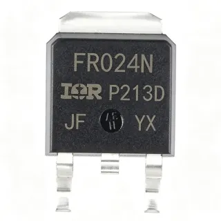
IRLR3110ZTRLPBF - 100V 63A N-Channel HEXFET MOSFET | Infineon
N.º da peça: IRLR3110ZTRLPBF ✓ Ativo| Qtd. | Preço unitário | Total |
|---|---|---|
| 1 | $1.42 | $1,42 |
| 10 | $1.18 | $11,80 |
| 100 | $0.94 | $94,00 |
| 500 | $0.78 | $390,00 |
| 1.000 | $0.65 | $650,00 |
IRLR3110ZTRLPBF Visão geral
An N-channel power MOSFET is a voltage-controlled semiconductor switch whose drain current is modulated by a gate-source voltage. The HEXFET family refers to Infineon/IInternational Rectifier's vertically-diffused trench MOSFET architecture, which sits in the broader power MOSFET category within discrete semiconductors. These devices are used as switching elements or low-resistance pass elements in power conversion systems, where their low RDS(on) minimizes conduction loss and their high-speed switching capability reduces switching loss.
Key specifications include VDS max of 100 V, RDS(on) max of 14 mΩ (or 11 mΩ per third-party listings), continuous drain current up to 42 A at TC and pulsed drain current rating supporting the 63 A ID max figure at lower temperature conditions, with gate charge of 34 nC. The logic-level gate drive simplifies interfacing directly to microcontrollers, gate drivers, and PWM controllers without requiring a separate charge-pump or bootstrap supply.
The TO-252AA (DPAK) package offers a low thermal-resistance path through the tab, with the part rated at 140 W power dissipation at TC. The exposed tab functions as the drain connection, while gate, drain, and source are arranged in the standard DPAK pinout. Repetitive-avalanche-rated cells and 175°C junction operation make this part suitable for rugged industrial environments with high inrush or unclamped inductive switching.
Typical applications include DC-DC converters in industrial 48 V bus systems, motor drive H-bridges for 24-72 V brushless DC motors, solenoid and relay drivers, power OR-ing, battery protection circuits, and primary-side switching for telecom bricks. Its logic-level gate and low RDS(on) also make it appropriate for hot-swap controllers and electronic fuse implementations.
When designing with this part, place the gate driver as close as possible to the gate pin and use a 10 kΩ pull-down on the gate to prevent false turn-on during power-up. Ensure the tab thermal pad carries at least 1 square inch of copper pour, and verify SOA against worst-case VDS and ID combinations before finalizing the design.
This page synthesizes distributor pricing, parametrically validated drop-in alternatives, and practical design notes not found in a single manufacturer datasheet or distributor listing.
Alternativas drop-in para IRLR3110ZTRLPBF — mesmo encapsulamento, compatível pino a pino. Peças de encapsulamento diferente que exigem retrabalho na PCB são excluídas.
Variantes desta série
Modelos da mesma série compatíveis como drop-in com IRLR3110ZTRLPBF (mesmo formato e footprint) — diferindo em RoHS Status, Technology.
Ferramenta de comparação rápida — selecione peças alternativas para comparação lado a lado:
IRLR3110ZTRPBF
✅ Drop-In✓ Em estoque
$0.66 / unidade
Ver ficha técnica →IRLR3110ZPBF
✅ Drop-In📋 Alternativa de referência (fora do catálogo)
AUIRLR3110ZTRL
✅ Drop-In📋 Alternativa de referência (fora do catálogo)
IRLR3110ZTRLPBF Classificações máximas e características elétricas
| Transistor Polarity | N-Channel |
| Drain-Source Voltage (VDS) | 100 V |
| Continuous Drain Current (ID) at TC | 42 A |
| Maximum Drain Current (ID max) | 63 A |
| On-Resistance (RDS(on) max) | 14 mOhm |
| Gate Charge (Qg) | 34 nC |
| Technology | IR HEXFET / Trench MOSFET |
| Gate Drive Level | Logic-Level |
| Power Dissipation (PD) at TC | 140 W |
| Temperatura de junção de operação | -55C to +175C |
| Encapsulamento | TO-252AA (DPAK) |
| Tipo de montagem | Surface Mount |
| Contagem de pinos | 3 (Drain, Gate, Source + Tab) |
| Repetitive Avalanche Rated | Yes |
| Status RoHS | Compliant (PBF suffix) |
Configuração de pinos do IRLR3110ZTRLPBF
| Pino 1 | Gate — Logic-level gate input for MOSFET control |
| Pino 2 | Drain — Power drain connection (also connected to tab) |
| Pino 3 | Source — Power source / return path |
| Pino Tab | Drain (Tab) — Exposed drain tab for electrical contact and thermal dissipation |
Área de Operação Segura (DC) - DPAK on 1 sq inch copper pour
Aplicações típicas
IRLR3110ZTRLPBF é adequado para 6 aplicaçãos: Industrial 48V DC-DC Converters, Brushless DC Motor Drive H-Bridges, Solenoid and Relay Driver Circuits, Battery Protection and Power OR-ing, Telecom Brick Primary-Side Switching, Hot-Swap and Electronic Fuse Circuits.
Industrial 48V DC-DC Converters
The IRLR3110ZTRLPBF is well-suited for primary-side switching in 48 V nominal industrial DC-DC converters stepping down to 12 V, 5 V, or 3.3 V logic rails. With VDS max of 100 V, the part provides comfortable headroom above the 48 V bus plus transients, while its 14 mΩ RDS(on) minimizes conduction loss at the high currents encountered in such converters. Placed on the low-side of a synchronous buck topology, the device's logic-level gate drive allows direct control from a 5 V or 3.3 V PWM controller without an additional gate-driver supply. The 175°C junction rating and repetitive-avalanche capability handle the high di/dt and unclamped energy events typical during output short or inductor saturation faults. Pair with companion gate drivers and controller ICs listed below.
Recomendado
Brushless DC Motor Drive H-Bridges
In 24-72 V brushless DC motor drives, the IRLR3110ZTRLPBF can be used as the low-side or high-side switching element in a three-phase H-bridge. The 42 A continuous drain current (63 A pulsed) easily drives mid-power industrial motors in the 1-3 kW range, while the logic-level gate input simplifies interfacing to 3.3 V MCUs. The repetitive-avalanche rating protects the device during regenerative braking events when back-EMF drives the drain above VDS max momentarily. Thermal management via the DPAK tab allows sustained high current without additional heatsinking in well-designed copper pours. Combine with companion gate drivers and position-sensing ICs for a complete motor-control solution.
Recomendado
Solenoid and Relay Driver Circuits
The IRLR3110ZTRLPBF is ideal for driving inductive loads such as 24 V or 48 V solenoids, relays, and contactors in industrial automation systems. The low RDS(on) of 14 mΩ means low-side switching dissipation is minimal even at the high inrush currents encountered when energizing large coils. Built-in repetitive avalanche rating protects the device during flyback events when the solenoid is de-energized without an external freewheeling diode. Logic-level gate drive allows direct switching from PLC outputs or microcontroller GPIOs without additional driver stages. The DPAK package's small footprint simplifies integration into multi-channel driver boards.
Recomendado
Battery Protection and Power OR-ing
The IRLR3110ZTRLPBF serves as a reverse-battery protection or power OR-ing MOSFET in 24-48 V battery-backed systems. Used as a low-side disconnect switch, its low RDS(on) keeps voltage drop minimal during normal operation, preserving efficiency. The 100 V VDS rating easily exceeds the typical 36-60 V battery voltages plus inductive transients when cables are hot-plugged. Logic-level gate drive simplifies control from battery-management ICs operating from 3.3 V or 5 V rails. The repetitive-avalanche rating protects against load-dump events in automotive or industrial 24 V truck systems. Pair with battery monitor ICs for complete protection.
Recomendado
Telecom Brick Primary-Side Switching
In isolated telecom DC-DC converters operating from 36-72 V input bus, the IRLR3110ZTRLPBF can be used on the primary side of a full-bridge or push-pull topology. The 100 V VDS rating provides adequate margin above 72 V input plus reflected secondary voltage and leakage spikes. Low RDS(on) reduces conduction loss during the high-current primary cycles typical of 1-3 kW brick converters. Logic-level gate drive simplifies interfacing to digital controllers that operate from 3.3 V. Repetitive-avalanche rating handles the energy stored in the transformer leakage inductance at turn-off. The DPAK footprint eases high-density PCB layout.
Recomendado
Hot-Swap and Electronic Fuse Circuits
The IRLR3110ZTRLPBF functions as the series pass element in 24-48 V hot-swap controllers and electronic fuse circuits, where its low RDS(on) minimizes voltage drop across the protection path. The logic-level gate enables closed-loop control with a hot-swap controller IC, allowing inrush current limiting and circuit-breaker behavior. The 100 V VDS rating supports 48 V nominal systems with margin for transients. The repetitive-avalanche rating protects the device during sudden load-dump events when the load is disconnected abruptly. The DPAK package's exposed tab provides efficient heat removal for sustained high current.
Recomendado
Resumo dos produtos recomendados
Dados de referência de engenharia para IRLR3110ZTRLPBF — comparação, orientação de projeto e informações de conformidade.
Guia de seleção
Comparação com alternativas
| Parâmetro | Este produto | IRLR3110ZTRPBF | IRLR3110ZPBF | AUIRLR3110ZTRL |
|---|---|---|---|---|
| Brand | Infineon | Infineon | Infineon | Infineon |
| Package | TO-252AA (DPAK) | TO-252AA (DPAK) | TO-252AA (DPAK) | TO-252AA (DPAK) |
| Drain-Source Voltage (VDS) | 100 V | 100 V | 100 V | 100 V |
| Continuous Drain Current at TC | 42 A | 42 A | 42 A | 42 A |
| Maximum Drain Current | 63 A | 63 A | 63 A | 63 A |
| On-Resistance RDS(on) max | 14 mOhm | 14 mOhm | 14 mOhm | 14 mOhm |
| Gate Charge Qg | 34 nC | 34 nC | 34 nC | 34 nC |
| Automotive Qualified | No | No | No | Yes (AEC-Q101) |
| Tape and Reel Orientation | Left | Standard | N/A (Tube) | Standard |
Principais diferenciais
- Logic-level gate drive for direct microcontroller interfacing (vs IRFB4110PBF (10V gate drive required))
- Lower on-resistance per silicon area via IR HEXFET trench technology (vs Standard planar MOSFETs in same package)
- Repetitive avalanche rated for unclamped inductive switching (vs Standard MOSFETs without avalanche rating)
- 175°C maximum junction temperature for industrial thermal margin (vs Standard 150°C rated MOSFETs)
Notas de projeto
Estimated: With TC held at 25C and 1 square inch of copper pour, the DPAK package theta_JA is approximately 50 C/W. At full 42 A continuous current with VIN = 50 V and VOUT = 0 V (worst case), dissipation approaches the 140 W limit. For sustained high-current operation, derate the part to keep junction below 150C. Use multiple thermal vias under the tab to a bottom-side copper plane for improved heat transfer. At a more realistic 5W dissipation (typical switching application), the part operates safely at 25C ambient.
Place the gate drive trace as short and direct as possible, with a 10 kΩ pull-down resistor from gate to source to prevent unintended turn-on during power-up or transient events. Keep the high-current drain and source loops minimal to reduce parasitic inductance that can cause voltage overshoot exceeding VDS max during switching. The exposed tab must be soldered to a copper pad of at least 80 mm² for proper thermal dissipation and electrical connection.
Do not exceed VDS max of 100 V - inductive load switching without proper snubbing can easily exceed this rating during turn-off. Verify SOA against worst-case continuous and pulsed conditions before deployment. The logic-level gate requires VGS of at least 4.5 V for full enhancement; lower gate voltages result in partial turn-on and dramatically higher RDS(on). Always check avalanche energy (EAS) rating when switching inductive loads without freewheeling diodes.
For double-sided PCBs, place thermal vias in a 3x3 grid pattern under the DPAK tab, each via approximately 0.3 mm diameter with 0.05 mm plating. Connect the via farm to a bottom-side copper pour that extends at least 100 mm². Avoid routing high-current traces directly under the package to prevent solder joint stress during thermal cycling. Use a land pattern compliant with IPC-7351 nominal DPAK dimensions for manufacturability.
Informações de conformidade
RoHS and REACH compliant per PBF suffix in MPN. Standard part is not AEC-Q100 qualified; choose AUIRLR3110ZTRL for AEC-Q101 automotive qualification. Lead-free reflow compatible per JESD22-A111.