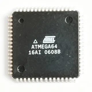
ATMEGA16-16AJ - 8-bit AVR MCU 16MHz 16KB TQFP-44 | Microchip
MPN: ATMEGA16-16AJ ✓ Hoạt độngATMEGA16-16AJ Tóm tắt
An 8-bit AVR microcontroller is a Harvard-architecture RISC processor that executes most of its 131 powerful instructions in a single clock cycle. Within the power-management and embedded-control hierarchy, the ATmega family sits in the mid-range tier between the tiny ATtiny series and the high-memory ATmega128 series, making it a classic general-purpose embedded controller for both new designs and legacy maintenance.
Key features include up to 16 MIPS throughput at 16 MHz, 16 KB of self-programmable Flash supporting boot-loader operation, and a 10-bit ADC with 8 multiplexed single-ended channels. Two 8-bit timers, one 16-bit timer, four PWM channels, UART, SPI, and two-wire (I2C-compatible) serial interfaces provide broad peripheral connectivity without external components.
Technically, the ATMEGA16-16AJ combines an advanced RISC core with 32 general-purpose working registers, all directly connected to the ALU, allowing two independent registers to be accessed in one instruction executed in a single clock cycle. The JTAG boundary-scan and on-chip-debug capability simplifies board-level test and firmware development. The 44-TQFP (10 x 10 mm) surface-mount package offers 32 programmable I/O lines.
Typical applications include industrial control and automation nodes, sensor acquisition systems leveraging the 8-channel 10-bit ADC, motor control and PWM actuation, and legacy design sustenance where the ATmega16 footprint is already qualified.
A key design consideration is clock sourcing: the -16AJ speed grade runs to 16 MHz, and the crystal or oscillator must stay within this limit; JTAG fuses should be disabled if port C pins PC2-PC5 are needed as general I/O.
This page synthesizes distributor pricing, drop-in same-family alternatives, pinout detail, and practical design notes not found in a single manufacturer datasheet.
Bộ thay thế dễ dàng lắp đặt cho ATMEGA16-16AJ — cùng gói, chân-to-chân tương thích. Các bộ phận yêu cầu hàn PCB bị loại trừ.
Các biến thể trong loạt này
Các mẫu cùng loạt có thể lắp đặt dễ dàng tương thích với ATMEGA16-16AJ (cùng hình factor và footprint) — khác nhau ở Package, Operating Temperature, Core Architecture, RoHS Status, SRAM.
ATMEGA16A-AU
✅ Drop-In ⚠️ Thông số chưa được xác minhLiên hệ để biết giá
Xem tài liệu →ATMEGA16-16AU
✅ Drop-InLiên hệ để biết giá
Xem tài liệu →ATMEGA16-16AUR
✅ Drop-InLiên hệ để biết giá
Xem tài liệu →ATMEGA32A-AU
✅ Drop-In ⚠️ Thông số chưa được xác minhLiên hệ để biết giá
Xem tài liệu →ATMEGA8535-16AU
✅ Drop-In ⚠️ Thông số chưa được xác minhLiên hệ để biết giá
Xem tài liệu →ATMEGA1609-AUR
✅ Drop-InLiên hệ để biết giá
Xem tài liệu →ATMEGA1608-AFR
✅ Drop-InLiên hệ để biết giá
Xem tài liệu →ATMEGA16-16AJ Tỷ lệ tối đa & tính chất điện
| Core | AVR 8-bit |
| Core Size | 8-Bit |
| Speed | 16 MHz |
| Flash Program Memory | 16 KB (8K x 16) |
| SRAM | 1 KB |
| EEPROM | 512 Bytes |
| ADC Resolution | 10-bit |
| ADC Channels | 8 |
| Number of I/O | 32 |
| Interfaces | UART, SPI, TWI (I2C), JTAG |
| Timers | Two 8-bit, one 16-bit |
| PWM Channels | 4 |
| Instructions | 131 (most single-cycle) |
| Throughput | Up to 16 MIPS at 16 MHz |
| On-Chip Debug | JTAG interface |
| Hộp | 44-TQFP (10 x 10 mm) |
| Kiểu lắp đặt | Surface Mount |
| Trạng thái RoHS | ROHS3 Compliant |
Cấu hình chân ATMEGA16-16AJ
| Chân 1 | PB0 — Port B bit 0 (T0/XCK) |
| Chân 2 | PB1 — Port B bit 1 (T1) |
| Chân 3 | PB2 — Port B bit 2 (AIN0/INT2) |
| Chân 4 | PB3 — Port B bit 3 (AIN1/OC0) |
| Chân 5 | PB4 — Port B bit 4 (SS) |
| Chân 6 | PB5 — Port B bit 5 (MOSI) |
| Chân 7 | PB6 — Port B bit 6 (MISO) |
| Chân 8 | PB7 — Port B bit 7 (SCK/OC2) |
| Chân 9 | RESET — Reset input (active low) |
| Chân 10 | VCC — Digital supply voltage |
| Chân 11 | GND — Ground |
| Chân 12 | XTAL2 — Oscillator output |
| Chân 13 | XTAL1 — Oscillator input |
| Chân 14 | PD0 — Port D bit 0 (RXD) |
| Chân 15 | PD1 — Port D bit 1 (TXD) |
| Chân 16 | PD2 — Port D bit 2 (INT0) |
| Chân 17 | PD3 — Port D bit 3 (INT1) |
| Chân 18 | PD4 — Port D bit 4 (OC1B) |
| Chân 19 | PD5 — Port D bit 5 (OC1A) |
| Chân 20 | PD6 — Port D bit 6 (ICP1) |
| Chân 21 | PD7 — Port D bit 7 (OC2 alt) |
| Chân 22 | PC0 — Port C bit 0 (SCL) |
| Chân 23 | PC1 — Port C bit 1 (SDA) |
| Chân 24 | PC2 — Port C bit 2 (TCK - shared with JTAG) |
| Chân 25 | PC3 — Port C bit 3 (TMS - shared with JTAG) |
| Chân 26 | PC4 — Port C bit 4 (TDO - shared with JTAG) |
| Chân 27 | PC5 — Port C bit 5 (TDI - shared with JTAG) |
| Chân 28 | PC6 — Port C bit 6 (TOSC1) |
| Chân 29 | PC7 — Port C bit 7 (TOSC2) |
| Chân 30 | AVCC — ADC supply voltage |
| Chân 31 | GND — Ground |
| Chân 32 | AREF — ADC analog reference |
| Chân 33 | PA0 — Port A bit 0 (ADC0) |
| Chân 34 | PA1 — Port A bit 1 (ADC1) |
| Chân 35 | PA2 — Port A bit 2 (ADC2) |
| Chân 36 | PA3 — Port A bit 3 (ADC3) |
| Chân 37 | PA4 — Port A bit 4 (ADC4) |
| Chân 38 | PA5 — Port A bit 5 (ADC5) |
| Chân 39 | PA6 — Port A bit 6 (ADC6) |
| Chân 40 | PA7 — Port A bit 7 (ADC7) |
| Chân 41 | PE0 — Port E bit 0 (TQFP package only) |
| Chân 42 | PE1 — Port E bit 1 (TQFP package only) |
| Chân 43 | GND — Ground |
| Chân 44 | VCC — Digital supply voltage |
Ứng dụng tiêu biểu
ATMEGA16-16AJ phù hợp cho 6 Áp dụngs: Industrial Control and Automation Nodes, Sensor Data Acquisition Systems, Motor Control and PWM Actuation, Legacy Design Sustenance and Repair, Embedded Education and Prototyping, Instrumentation Front Panels and HMI.
Industrial Control and Automation Nodes
The ATMEGA16-16AJ fits factory automation I/O nodes because it combines 32 programmable I/O lines with four PWM channels and hardware UART, SPI, and TWI interfaces in a single 16 MHz 8-bit AVR core. In a typical relay-and-sensor control panel, the 8-channel 10-bit ADC samples analog setpoints while port B/D drive opto-isolated outputs, and the UART carries a Modbus RTU link at up to 115.2 kbaud. JTAG on-chip debugging lets engineers set breakpoints on the target board during commissioning, reducing bring-up time. The 16 KB self-programming Flash also supports field firmware updates via a boot-loader, an important benefit for deployed industrial equipment.
Được đề xuất
Sensor Data Acquisition Systems
With an 8-channel 10-bit ADC multiplexed to port A, the ATMEGA16-16AJ is a natural fit for multi-sensor acquisition boards such as temperature, pressure, and level monitoring units. The ADC supports single-ended and differential conversions, and the 1 KB SRAM buffers sample arrays before transmission over UART or TWI to a host controller. Running the ADC with a 16 MHz system clock yields usable conversion rates for slow industrial signals, while the 512-byte EEPROM stores calibration constants that survive power cycles. The 44-TQFP package keeps the full analog and digital pin set available for a dense mixed-signal layout on a two-layer board.
Được đề xuất
Motor Control and PWM Actuation
The ATMEGA16-16AJ provides four hardware PWM outputs (two 8-bit timers with compare channels and one 16-bit timer with OC1A/OC1B), enabling closed-loop DC motor and stepper control without software bit-banging overhead. At 16 MHz, 8-bit PWM resolution achieves roughly 62.5 kHz carrier frequency, high enough for quiet brushless fan and small motor drive, while the 16-bit timer delivers fine-grained servo control. The 10-bit ADC reads back current-sense resistors or potentiometer position for proportional feedback. Its 32 I/O lines leave ample capacity for limit switches, encoder inputs, and status LEDs in the same footprint.
Được đề xuất
Legacy Design Sustenance and Repair
A large installed base of products built around the ATmega16 continues to require maintenance parts. The ATMEGA16-16AJ in 44-TQFP is drop-in interchangeable with the ATMEGA16-16AU and ATMEGA16A-AU, making it the correct sustenance choice for PCBs whose land patterns cannot change. Because the AVR toolchain (AVR-GCC, MPLAB X, JTAG ICE) still supports the family, existing firmware recompiles and reflashes without rework. Keeping verified stock of this RoHS3-compliant order code avoids the counterfeit risk common on obsolete-marketed 8-bit MCUs, and the JTAG port allows verification of salvaged or refurbished boards.
Được đề xuất
Embedded Education and Prototyping
The ATmega16 remains a staple in university embedded-systems courses because its 131-instruction RISC set, straightforward register map, and JTAG debug make fundamental concepts visible without abstraction layers. The 44-TQFP package is hand-solderable with practice or with a hot-plate, and single-chip boards need only a crystal, decoupling caps, and an ISP header to run. Community support through the MightyCore Arduino hardware package allows ATmega16 boards to run Arduino-style sketches, bridging classroom exercises to the broader hobbyist ecosystem. Four PWM channels and the 8-channel ADC support introductory robotics, display, and sensor laboratory exercises.
Được đề xuất
Instrumentation Front Panels and HMI
Human-machine interface boards benefit from the ATMEGA16-16AJ's balance of I/O count and serial connectivity. Port C can directly drive multiplexed 7-segment or LED matrices through sink transistors, while the UART communicates with a host PLC or a TWI-connected OLED controller. Timer-based scanning runs autonomously, so key debouncing and display refresh cost little CPU time at 16 MIPS throughput. In response-critical equipment such as benchtop power supplies and test fixtures, the deterministic single-cycle execution of the AVR core gives predictable interrupt latency, and the 512-byte EEPROM retains user settings such as setpoints and calibration offsets between power cycles.
Được đề xuất
Tóm tắt các sản phẩm được đề xuất
Dữ liệu tham khảo kỹ thuật cho ATMEGA16-16AJ — so sánh, hướng dẫn thiết kế và thông tin tuân thủ.
Hướng dẫn chọn lựa
So sánh với các sản phẩm thay thế
| Tham số | Sản phẩm này | ATMEGA16A-AU | ATMEGA16-16AU | ATMEGA32A-AU | ATMEGA8535-16AU | ATMEGA1609-AUR |
|---|---|---|---|---|---|---|
| Package | 44-TQFP (10 x 10 mm) | 44-TQFP (10 x 10 mm) - same | 44-TQFP (10 x 10 mm) - same | 44-TQFP (10 x 10 mm) - same | 44-TQFP (10 x 10 mm) - same | 44-TQFP (10 x 10 mm) - same |
| Brand | Microchip Technology | Microchip Technology | Microchip Technology | Microchip Technology | Microchip Technology | Microchip Technology |
| Flash Program Memory | 16 KB | 16 KB | 16 KB | 32 KB | 8 KB | 16 KB |
| SRAM | 1 KB | 1 KB | 1 KB | 2 KB | 512 B | 2 KB |
| EEPROM | 512 Bytes | 512 Bytes | 512 Bytes | 1 KB | 512 Bytes | 256 Bytes |
| Max Speed | 16 MHz | 16 MHz | 16 MHz | 16 MHz | 16 MHz | 20 MHz |
| ADC | 8-ch 10-bit | 8-ch 10-bit | 8-ch 10-bit | 8-ch 10-bit | 8-ch 10-bit | 10-ch 12-bit |
| JTAG Debug | Yes | Yes | Yes | Yes | No | No (UPDI debug) |
| RoHS | ROHS3 Compliant | Compliant | Compliant | Compliant | Compliant | Compliant |
Bảo phân biệt quan trọng
- Hardware JTAG on-chip debugging at classic-AVR price point (vsATMEGA8535-16AU)
- Balanced memory configuration for mid-size firmware (vsATMEGA8535-16AU)
- 32 I/O plus TQFP-only port E pins (vsATMEGA32A-AU)
- Mature toolchain and ecosystem at cost of modern peripherals (vsATMEGA1609-AUR)
Ghi chú thiết kế
Decouple both VCC pins (10, 44) and AVCC (pin 30) with 100 nF ceramic capacitors placed within 5 mm of each pin, plus one 10 uF bulk capacitor per supply rail. Connect AVCC to VCC through a low-pass LC filter (10 uH + 100 nF) when ADC accuracy matters, and keep the analog ground region under port A star-connected to digital ground at a single point near pin 31. The 44-TQFP exposed-leadless geometry tolerates standard 0.5 mm pitch footprints per IPC-7351 conventions; verify paste aperture reduction for reflow assembly.
JTAG pins (PC2-PC5, TCK/TMS/TDO/TDI) are enabled by default via the JTAGEN fuse. If your application needs those port C pins as general I/O, disable JTAGEN in the fuse bits - a software-only disable via JTD bit requires writing it twice within four cycles, which is easy to get wrong. Also note the -16AJ speed grade tops out at 16 MHz: setting CKSEL fuses for a 20 MHz crystal violates the datasheet maximum and causes unreliable operation across temperature. Always verify fuse settings with a programmer read-back before mass programming.
Keep the XTAL1/XTAL2 crystal traces (pins 12-13) shorter than 10 mm and guard them with ground pour; long oscillator traces pick up digital switching noise from the UART and PWM outputs and cause missed clock edges. For ADC lines on port A, route away from PWM outputs (PD4/PD5) and series-terminate long lines into connectors with 22-33 ohm resistors to limit ringing. When using external interrupts INT0/INT1 (PD2/PD3) from mechanically noisy sources, enable the internal pull-up and add RC filtering in firmware rather than relying on hardware alone.
Estimated: at VCC = 5 V and 16 MHz active mode, the ATmega16 draws roughly 11-12 mA typical (active mode figure from the classic AVR family class), so a 5 V rail sized at 50 mA per MCU with margin covers the core plus LEDs. Add external current only for I/O loads: each pin sources/sinks up to 20 mA recommended (40 mA absolute max), and the total device current limit of the classic AVR 44-TQFP family must be observed - budget I/O current against your regulator, not the MCU pin rating alone.
Thông tin tuân thủ
ROHS3 compliant per Full-Electronic.com product data as of 2026-09-16. REACH, halogen-free, and conflict-minerals status not stated in the provided web data - request Microchip material declarations for full compliance documentation.