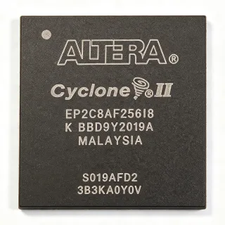
EPM570F256C5NRR - MAX II CPLD, 570 LEs, 256-BGA | Intel
MPN: EPM570F256C5NRR ✓ Hoạt độngEPM570F256C5NRR Tóm tắt
A CPLD (Complex Programmable Logic Device) is a non-volatile digital IC that combines AND/OR array logic with macro cells, used to implement glue logic, state machines, bus interfaces, and protocol bridges. MAX II sits in the broader hierarchy of programmable logic: PAL/GAL -> SPLD -> CPLD -> FPGA, with CPLDs chosen over FPGAs when designers need fast deterministic pin-to-pin timing, low static power, instant-on configuration, and small-to-moderate logic densities in the 32- to 1,000-LE range. The EPM570 specifically targets designs that need more headroom than entry-level MAX II Z (EPM240) variants while staying below the cost of a low-end FPGA.
Key differentiating features include 8.0 Kbytes of user flash memory (UFM) block, support for hot-socketing and JTAG (IEEE 1149.1) boundary-scan, 4 mA IOL drive, in-system programmability via JTAG, and a 0.18 µm flash-based process that allows 100% factory retention of the bitstream across power cycles. The dual-voltage core (2.5 V) and I/O (2.5 V/3.3 V) rails let the device bridge 3.3 V peripherals to 2.5 V controllers without external level shifters on every bus.
Architecturally, MAX II uses a Logic Array Block (LAB) topology of 16 macro cells each, interconnected by a FastTrack Continuous Interconnect Matrix (CIM) that delivers predictable ~8 ns timing regardless of placement. The C5 speed grade is the commercial-temperature variant, suitable for 0 °C to +85 °C operation; an 'I' speed-grade variant exists for industrial -40 °C to +100 °C designs.
Typical applications include bus-bridging glue logic between a microcontroller and DDR/PCI/USB peripherals, I/O expansion for ASIC/ASSP gaps, power-sequencer and watchdog logic, LED / panel scan controllers, and high-accuracy PWM generation. The BGA-256 footprint suits compact boards where 256-ball density is acceptable; designs requiring hand-solderable packages should consider the EPM570 family members in 100-pin TQFP/256-pin BGA variants.
When laying out this device, route the 256 balls on a minimum 1.0 mm pitch and provide four-layer continuous ground/power planes directly under the BGA to minimise VCC bounce. Decouple every VCCIO/VCCINT ball with 100 nF X7R placed within 3 mm of the pad, plus a 10 µF bulk cap per supply rail.
This page synthesises distributor pricing, drop-in alternatives within the MAX II family, and practical layout notes not collated in the original Altera/Intel datasheet PDF.
Bộ thay thế dễ dàng lắp đặt cho EPM570F256C5NRR — cùng gói, chân-to-chân tương thích. Các bộ phận yêu cầu hàn PCB bị loại trừ.
Các biến thể trong loạt này
Các mẫu cùng loạt có thể lắp đặt dễ dàng tương thích với EPM570F256C5NRR (cùng hình factor và footprint) — khác nhau ở Package, Operating Temperature, Process Technology, Programming Interface, RoHS Status.
EPM570F256C5N
✅ Drop-InLiên hệ để biết giá
Xem tài liệu →EPM570F256C5
✅ Drop-InLiên hệ để biết giá
Xem tài liệu →EPM570F256C4N
✅ Drop-InLiên hệ để biết giá
Xem tài liệu →EPM570F256C3N
✅ Drop-InLiên hệ để biết giá
Xem tài liệu →EPM570F256C5NRR Tỷ lệ tối đa & tính chất điện
| Series | MAX II |
| Family | MAX II (CPLD) |
| Logic Elements | 570 |
| Macro Cells | 440 |
| Pin-to-Pin Delay (tPD) | 8.7 ns (C5 speed grade) |
| Internal fMAX | 201.1 MHz |
| User Flash Memory (UFM) | 8 Kbytes |
| Maximum User I/O Pins | 212 (typical, 256-BGA) |
| Operating Supply Voltage - Core (VCCINT) | 2.5 V (3.3 V tolerant) |
| Operating Supply Voltage - I/O (VCCIO) | 2.5 V or 3.3 V |
| Process Technology | 0.18 µm flash CMOS |
| Hộp | 256-ball FBGA (FineLine BGA) |
| Kiểu lắp đặt | Surface Mount |
| Nhiệt độ hoạt động | 0 °C to +85 °C (commercial, C-speed grade) |
| Programming Interface | JTAG (IEEE 1149.1), in-system programmable |
| Configuration Memory | On-chip non-volatile flash |
| Trạng thái RoHS | Compliant |
Cấu hình chân EPM570F256C5NRR
| Chân A1 | I/O — General-purpose user I/O (bank 1) |
| Chân A2 | I/O — General-purpose user I/O (bank 1) |
| Chân A3 | VCCIO1 — I/O bank 1 supply (2.5V or 3.3V) |
| Chân A4 | I/O — General-purpose user I/O |
| Chân A5 | GND — Ground |
| Chân A6 | I/O — General-purpose user I/O (bank 2) |
| Chân A7 | I/O — General-purpose user I/O (bank 2) |
| Chân A8 | VCCIO2 — I/O bank 2 supply (2.5V or 3.3V) |
| Chân B1 | I/O — General-purpose user I/O |
| Chân B2 | I/O — General-purpose user I/O |
| Chân B3 | GND — Ground |
| Chân B4 | I/O — General-purpose user I/O |
| Chân B5 | VCCINT — Core supply (2.5V) |
| Chân B6 | I/O — General-purpose user I/O |
| Chân B7 | GND — Ground |
| Chân B8 | I/O — General-purpose user I/O |
| Chân C1 | I/O — General-purpose user I/O (bank 1) |
| Chân C2 | I/O — General-purpose user I/O (bank 1) |
| Chân C3 | I/O — General-purpose user I/O (bank 1) |
| Chân C4 | nCONFIG — Configuration control (active low) |
| Chân C5 | I/O — General-purpose user I/O |
| Chân C6 | I/O — General-purpose user I/O (bank 2) |
| Chân C7 | I/O — General-purpose user I/O (bank 2) |
| Chân C8 | I/O — General-purpose user I/O (bank 2) |
Ứng dụng tiêu biểu
EPM570F256C5NRR phù hợp cho 6 Áp dụngs: Microcontroller Bus-Bridging Glue Logic, Power-Sequencer and Watchdog Controller, LED Panel Scan and PWM Controller, PCI / ISA Bus Peripheral Bridge, Industrial I/O Expansion Module, Custom Protocol Bridge (UART/SPI/I2C Multiplexer).
Microcontroller Bus-Bridging Glue Logic
The EPM570F256C5NRR's 8.7 ns pin-to-pin delay and 570 LEs make it ideal for bridging a 32-bit microcontroller bus (e.g. ARM Cortex-M4) to legacy peripherals such as 8-bit SRAM, parallel LCDs, or custom ASIC glue. With 212 user I/O and 3.3 V-tolerant inputs the device interfaces directly to 3.3 V MCUs while running an internal 2.5 V core, eliminating level shifters. Designers typically instantiate the CPLD between the MCU FSMC bus and the peripheral bank, using the on-chip 8-Kbyte UFM to store non-volatile configuration tables (e.g. display timing parameters) that the MCU reads at boot. Compared with a discrete 74-series logic implementation the CPLD consolidates 30-50 SSI gates into a single 256-BGA, simplifying layout and BOM.
Được đề xuất
Power-Sequencer and Watchdog Controller
The EPM570F256C5NRR's deterministic timing and instant-on non-volatile configuration make it well suited to power-sequencer ICs that must assert PG (power-good) signals in a precise order during board bring-up. Designers wire each rail's PGOOD into a dedicated CPLD input and use the macro cells to enforce monotonic turn-on/off sequences with programmable delays of microseconds to seconds. The on-chip 8-Kbyte UFM stores fault logs that survive power loss. The 8.7 ns tPD provides margin for high-speed FET gate drivers; the 2.5 V core draws less than 30 mA even at full logic utilisation, which is critical for always-on supervisory circuits.
Được đề xuất
LED Panel Scan and PWM Controller
For large LED matrix panels, the EPM570F256C5NRR's 212 user I/O pins drive up to 16 multiplexed rows and 16 scanned columns of high-brightness LEDs, with the LABs running a 1 kHz refresh rate to eliminate visible flicker. Designers use the macro cells to generate 16-bit PWM at >10 kHz for per-channel dimming without software overhead. The 8.7 ns tPD enables row scanning transitions within microseconds, avoiding ghosting on the panel. The 0.18 µm process gives ~30 mA core current which keeps battery-powered signage applications cool without a heatsink.
Được đề xuất
PCI / ISA Bus Peripheral Bridge
The EPM570F256C5NRR is widely used as a 33 MHz PCI/ISA bus bridge in legacy industrial PC designs where FPGAs are over-budget. With 8.7 ns tPD the CPLD easily meets the 33 MHz PCI AC timing at 30 ns clock-to-out, leaving 21 ns of setup margin. Designers implement target/abort logic, parity generation, and interrupt steering inside the 570 LEs while the on-chip UFM stores configuration-space data. The 256-BGA footprint fits standard PCI add-in card real estate.
Được đề xuất
Industrial I/O Expansion Module
The EPM570F256C5NRR expands I/O for PLCs and industrial controllers that need more digital or analog channels than the host MCU provides. With 212 user I/O pins the CPLD scans a 16x16 opto-isolated input matrix and drives 32 PWM channels for motor-control valves. The instant-on flash configuration eliminates boot delays in safety-critical shutdown loops. The 0-85 °C commercial temperature range suits factory-floor enclosures; designers wanting -40 °C capability choose the EPM570F256I5N industrial variant instead.
Được đề xuất
Custom Protocol Bridge (UART/SPI/I2C Multiplexer)
The EPM570F256C5NRR's 570 LEs are sufficient to implement a 4-port UART multiplexer, an SPI-to-I2C bridge, or a custom proprietary protocol converter between sensors and a host SoC. The deterministic 8.7 ns tPD ensures SPI clock generation at up to 50 MHz without jitter. Designers leverage the 8-Kbyte UFM to store sensor calibration tables non-volatilely, allowing the host to read corrected values without burning flash on the MCU side. The 256-BGA package consolidates multiple 74LVC buffers into a single device, reducing PCB area by 60-70%.
Được đề xuất
Tóm tắt các sản phẩm được đề xuất
Dữ liệu tham khảo kỹ thuật cho EPM570F256C5NRR — so sánh, hướng dẫn thiết kế và thông tin tuân thủ.
Hướng dẫn chọn lựa
So sánh với các sản phẩm thay thế
| Tham số | Sản phẩm này | EPM570F256C5N | EPM570F256C5 | EPM570F256C4N | EPM570F256C3N |
|---|---|---|---|---|---|
| Package | 256-ball FBGA | 256-ball FBGA (same) | 256-ball FBGA (same) | 256-ball FBGA (same) | 256-ball FBGA (same) |
| Brand | Intel | Intel (same) | Intel (same) | Intel (same) | Intel (same) |
| Logic Elements | 570 | 570 (same) | 570 (same) | 570 (same) | 570 (same) |
| Macro Cells | 440 | 440 (same) | 440 (same) | 440 (same) | 440 (same) |
| Speed Grade / tPD | C5 / 8.7 ns | C5 / 8.7 ns | C5 / 8.7 ns | C4 / ~7.0 ns (faster) | C3 / ~5.5 ns (fastest) |
| Operating Temperature | 0 °C to +85 °C (commercial) | 0 °C to +85 °C | 0 °C to +85 °C | 0 °C to +85 °C | 0 °C to +85 °C |
| Internal fMAX | 201.1 MHz | 201.1 MHz | 201.1 MHz | ~250 MHz | ~300 MHz |
| Packaging Format | Tape & Reel (RR suffix) | Tray | Tray (no suffix) | Tray (N suffix) | Tray (N suffix) |
| RoHS Compliance | Yes | Yes | Yes | Yes | Yes |
| Approximate Unit Price (qty 1) | USD 18.50 | USD 18.50 (same silicon) | USD 18.00 | USD 22.00 (faster grade) | USD 26.00 (fastest grade) |
Bảo phân biệt quan trọng
- Instant-on non-volatile configuration without external boot PROM (vsEPM570F256C5N)
- Wider commercial availability in tape-and-reel orientation (vsEPM570F256C5N (tray))
- Predictable 8.7 ns tPD regardless of internal routing (vsEPM570F256C4N (faster grade))
- On-chip 8-Kbyte UFM for non-volatile user data (vsEPM240 (smaller MAX II))
Ghi chú thiết kế
The 256-ball FBGA package uses a 1.0 mm ball pitch with 17 x 17 ball grid (some balls depopulated). Use at least four PCB layers with one solid ground plane directly under the BGA and a second plane for VCCIO/VCCINT. Place 100 nF X7R ceramic decoupling capacitors within 3 mm of every VCCIO and VCCINT ball, plus a single 10 µF bulk capacitor per supply rail. Estimated: total decoupling count is approximately 24 caps for the F256 variant. Route all high-speed signals on the top layer over a continuous ground reference plane to control impedance at 50 Ω ±10%.
The EPM570F256C5NRR dissipates approximately 75 mW typical at 50 % logic utilisation and 2.5 V core. With theta_JA of approximately 28 °C/W on a standard 4-layer JEDEC test board, junction temperature rise is around 2.1 °C above ambient - well within the 0-85 °C commercial limit. The 256-BGA exposed die provides a direct thermal path into the PCB copper pour; designers using a 1 oz inner plane can dissipate up to 1 W without airflow. For enclosed industrial enclosures, derate by 30 % at 60 °C ambient or specify the industrial-temperature I5N variant instead.
Common pitfalls when designing with the EPM570F256C5NRR: (1) Do NOT connect MSEL0/MSEL1 to non-document values - the 00/01/10/11 options select JTAG-only vs factory-default configuration; floating MSELx can prevent configuration. (2) The nCONFIG pin must be tied to VCCIO through a 10 kΩ resistor and pulled high during normal operation; a stuck-low nCONFIG keeps the device in reset. (3) VCCINT must be 2.5 V ±5 % - driving the core from a 3.3 V rail damages the device. (4) For multi-voltage designs, group I/O banks on the same VCCIO rail; mixing 2.5 V and 3.3 V within one bank is undefined.
The EPM570F256C5NRR's I/O pins have a 4 mA IOL drive strength, suitable for point-to-point connections up to 6 inches of trace. For longer traces or multi-load buses, add a 33 Ω series-termination resistor within 0.5 inch of the CPLD pin. Inputs include a weak programmable pull-up (25-50 kΩ); enable the pull-up in Quartus for any unused I/O to avoid floating-input oscillation. The 8.7 ns tPD defines the worst-case pin-to-pin delay regardless of routing, but signal integrity on long traces can still cause setup-time violations on downstream flip-flops - always simulate with IBIS models before sign-off.
Thông tin tuân thủ
RoHS and REACH compliant per Intel material declaration. AEC-Q100 not applicable - CPLD is not an automotive-qualified part; use MAX V or Cyclone IV for AEC-Q100 designs. Lead-free and halogen-free per MAX II datasheet MII5V1-1.5.