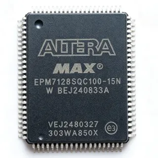
EPM7128SQC100-7 - 128-Macro 5V CPLD, 7.5ns, 100-Pin PQFP | Altera (Intel)
MPN: EPM7128SQC100-7 ✗ Cuối đờiEPM7128SQC100-7 Tóm tắt
A CPLD (Complex Programmable Logic Device) is a non-volatile, instantly-on programmable logic device that sits between discrete glue-logic ICs and larger FPGAs. Within the broader semiconductor taxonomy, the EPM7128SQC100-7 belongs to the CPLD category -> programmable logic -> digital IC -> semiconductor. MAX 7000S devices use a classic EEPROM-based architecture, providing deterministic timing, infinite reconfigurability (over 100 program/erase cycles), and 100% non-volatile storage so designs power up in a known state without external boot memory.
Key features include 2,500 usable gates, a maximum internal operating frequency of 125 MHz (with some sources citing up to 250 MHz internal), 5.0V VCCIO/VCCINT operation, in-system programmability through a standard 4-pin JTAG interface (IEEE Std 1149.1), and built-in support for the MAX+PLUS II and Quartus development flows. The device includes 128 macro cells, each composed of a programmable AND/OR array feeding a configurable flip-flop, and provides flexible I/O standards including TTL and CMOS.
Architecturally, the EPM7128SQC100-7 organizes its 128 macro cells into four Logic Array Blocks (LABs) interconnected through the Programmable Interconnect Array (PIA). This matrix-based interconnect delivers predictable, fixed-delay signal routing - a key advantage over SRAM-based FPGAs for deterministic glue-logic, bus-interface, address-decoding, and timing-critical applications where race conditions must be eliminated.
Typical applications include bus-interface bridging (e.g., 8-bit/16-bit microprocessor glue logic), address decoding and chip-select generation, state-machine controllers, peripheral interface expansion, and legacy 5V system designs that require non-volatile, instantly-on logic. The 84 available user I/Os accommodate wide parallel buses and multi-channel control logic.
When designing with this device, plan for a single 5V supply rail and verify that total output loading plus simultaneous switching I/O does not exceed the thermal envelope. For new designs, note that the MAX 7000 family is in legacy support - consider the MAX II or MAX V series for cost-sensitive modern designs, but the EPM7128 remains a proven solution for sustaining legacy 5V systems and as a pin-compatible firmware drop-in.
This page synthesizes distributor pricing (as of 2026-09-13), drop-in pin-compatible alternatives (including the Atmel/Microchip ATF1508AS family noted by the Intel/Altera community as a silicon drop-in), practical design notes, and a parameter comparison matrix not found in the original datasheet alone.
Bộ thay thế dễ dàng lắp đặt cho EPM7128SQC100-7 — cùng gói, chân-to-chân tương thích. Các bộ phận yêu cầu hàn PCB bị loại trừ.
Các biến thể trong loạt này
Các mẫu cùng loạt có thể lắp đặt dễ dàng tương thích với EPM7128SQC100-7 (cùng hình factor và footprint) — khác nhau ở Package, Logic Array Blocks (LABs), RoHS Status, Operating Temperature, Device Type.
EPM7128SQC100-6
✅ Drop-InLiên hệ để biết giá
Xem tài liệu →EPM7128SQC100-10
✅ Drop-InLiên hệ để biết giá
Xem tài liệu →EPM7128SQC100-10N
✅ Drop-InLiên hệ để biết giá
Xem tài liệu →EPM7128SQC100-15
✅ Drop-In✗ Hết hàng
$8.2 / Đơn vị
Xem tài liệu →EPM7128SQC100-10F
✅ Drop-InLiên hệ để biết giá
Xem tài liệu →ATF1508AS-7AX100
✅ Drop-In📋 Tham chiếu thay thế (không có trong danh mục)
EPM7128SQC100-7 Tỷ lệ tối đa & tính chất điện
| Product Type | CPLD - Complex Programmable Logic Device |
| Family | MAX 7000S |
| Macro Cells | 128 |
| Usable Gates | 2,500 |
| User I/Os | 84 |
| Logic Elements / LABs | 4 Logic Array Blocks (LABs) |
| Propagation Delay (tPD) | 7.5 ns |
| Maximum Internal Frequency | 125 MHz |
| Supply Voltage (VCCINT/VCCIO) | 5.0 V |
| Technology | CMOS, EEPROM-based, non-volatile |
| Hộp | 100-pin PQFP (Plastic Quad Flat Pack) |
| Programming Interface | JTAG (IEEE Std 1149.1), in-system programmable |
| Kiểu lắp đặt | Surface Mount |
| Trạng thái RoHS | Non-RoHS (legacy SnPb package) |
Cấu hình chân EPM7128SQC100-7
| Chân 1 | I/O — User I/O pin (bank 1) |
| Chân 2 | I/O — User I/O pin (bank 1) |
| Chân 3 | I/O — User I/O pin (bank 1) |
| Chân 4 | I/O — User I/O pin (bank 1) |
| Chân 5 | I/O — User I/O pin (bank 1) |
| Chân 6 | I/O — User I/O pin (bank 1) |
| Chân 7 | I/O — User I/O pin (bank 1) |
| Chân 8 | I/O — User I/O pin (bank 1) |
| Chân 9 | I/O — User I/O pin (bank 1) |
| Chân 10 | I/O — User I/O pin (bank 1) |
| Chân 11 | GND — Ground |
| Chân 12 | I/O — User I/O pin (bank 1) |
| Chân 13 | I/O — User I/O pin (bank 1) |
| Chân 14 | I/O — User I/O pin (bank 1) |
| Chân 15 | I/O — User I/O pin (bank 1) |
| Chân 16 | I/O — User I/O pin (bank 1) |
| Chân 17 | I/O — User I/O pin (bank 1) |
| Chân 18 | I/O — User I/O pin (bank 1) |
| Chân 19 | I/O — User I/O pin (bank 1) |
| Chân 20 | I/O — User I/O pin (bank 1) |
| Chân 21 | GND — Ground |
| Chân 22 | I/O — User I/O pin (bank 1) |
| Chân 23 | I/O — User I/O pin (bank 1) |
| Chân 24 | I/O — User I/O pin (bank 1) |
| Chân 25 | I/O — User I/O pin (bank 1) |
| Chân 26 | I/O — User I/O pin (bank 1) |
| Chân 27 | I/O — User I/O pin (bank 1) |
| Chân 28 | I/O — User I/O pin (bank 1) |
| Chân 29 | I/O — User I/O pin (bank 1) |
| Chân 30 | I/O — User I/O pin (bank 1) |
| Chân 31 | GND — Ground |
| Chân 32 | I/O — User I/O pin (bank 2) |
| Chân 33 | I/O — User I/O pin (bank 2) |
| Chân 34 | I/O — User I/O pin (bank 2) |
| Chân 35 | I/O — User I/O pin (bank 2) |
| Chân 36 | I/O — User I/O pin (bank 2) |
| Chân 37 | I/O — User I/O pin (bank 2) |
| Chân 38 | I/O — User I/O pin (bank 2) |
| Chân 39 | I/O — User I/O pin (bank 2) |
| Chân 40 | I/O — User I/O pin (bank 2) |
| Chân 41 | GND — Ground |
| Chân 42 | I/O — User I/O pin (bank 2) |
| Chân 43 | I/O — User I/O pin (bank 2) |
| Chân 44 | I/O — User I/O pin (bank 2) |
| Chân 45 | I/O — User I/O pin (bank 2) |
| Chân 46 | I/O — User I/O pin (bank 2) |
| Chân 47 | I/O — User I/O pin (bank 2) |
| Chân 48 | I/O — User I/O pin (bank 2) |
| Chân 49 | I/O — User I/O pin (bank 2) |
| Chân 50 | I/O — User I/O pin (bank 2) |
| Chân 51 | GND — Ground |
| Chân 52 | I/O — User I/O pin (bank 2) |
| Chân 53 | I/O — User I/O pin (bank 2) |
| Chân 54 | I/O — User I/O pin (bank 2) |
| Chân 55 | I/O — User I/O pin (bank 2) |
| Chân 56 | I/O — User I/O pin (bank 2) |
| Chân 57 | I/O — User I/O pin (bank 2) |
| Chân 58 | I/O — User I/O pin (bank 2) |
| Chân 59 | I/O — User I/O pin (bank 2) |
| Chân 60 | I/O — User I/O pin (bank 2) |
| Chân 61 | GND — Ground |
| Chân 62 | I/O — User I/O pin (bank 3) |
| Chân 63 | I/O — User I/O pin (bank 3) |
| Chân 64 | I/O — User I/O pin (bank 3) |
| Chân 65 | I/O — User I/O pin (bank 3) |
| Chân 66 | I/O — User I/O pin (bank 3) |
| Chân 67 | I/O — User I/O pin (bank 3) |
| Chân 68 | I/O — User I/O pin (bank 3) |
| Chân 69 | I/O — User I/O pin (bank 3) |
| Chân 70 | I/O — User I/O pin (bank 3) |
| Chân 71 | GND — Ground |
| Chân 72 | I/O — User I/O pin (bank 3) |
| Chân 73 | TDI — JTAG Test Data In |
| Chân 74 | TMS — JTAG Test Mode Select |
| Chân 75 | TCK — JTAG Test Clock |
| Chân 76 | GND — Ground |
| Chân 77 | VCC — 5V Supply |
| Chân 78 | I/O — User I/O pin (bank 3) |
| Chân 79 | I/O — User I/O pin (bank 3) |
| Chân 80 | I/O — User I/O pin (bank 3) |
| Chân 81 | I/O — User I/O pin (bank 3) |
| Chân 82 | I/O — User I/O pin (bank 3) |
| Chân 83 | GLOBAL_CLK — Global clock input 1 |
| Chân 84 | GLOBAL_CLK — Global clock input 2 |
| Chân 85 | I/O — User I/O pin (bank 4) |
| Chân 86 | I/O — User I/O pin (bank 4) |
| Chân 87 | I/O — User I/O pin (bank 4) |
| Chân 88 | I/O — User I/O pin (bank 4) |
| Chân 89 | I/O — User I/O pin (bank 4) |
| Chân 90 | I/O — User I/O pin (bank 4) |
| Chân 91 | GND — Ground |
| Chân 92 | I/O — User I/O pin (bank 4) |
| Chân 93 | I/O — User I/O pin (bank 4) |
| Chân 94 | I/O — User I/O pin (bank 4) |
| Chân 95 | I/O — User I/O pin (bank 4) |
| Chân 96 | I/O — User I/O pin (bank 4) |
| Chân 97 | I/O — User I/O pin (bank 4) |
| Chân 98 | I/O — User I/O pin (bank 4) |
| Chân 99 | I/O — User I/O pin (bank 4) |
| Chân 100 | TDO — JTAG Test Data Out |
Ứng dụng tiêu biểu
EPM7128SQC100-7 phù hợp cho 6 Áp dụngs: Microprocessor Glue Logic and Address Decoding, Bus Interface Bridging and Protocol Conversion, State Machine Controllers, Peripheral Interface Expansion, Legacy 5V System Sustainment, Industrial Control and Instrumentation Front-End.
Microprocessor Glue Logic and Address Decoding
The EPM7128SQC100-7 excels at replacing discrete 74-series glue logic with a single 5V CPLD, consolidating address decoding, chip-select generation, wait-state insertion, and bus steering for 8/16/32-bit microprocessors. With 128 macro cells and 84 user I/Os, it can decode the full 24-bit address range of an 8086/MC68000 system, generate up to 12 chip selects, and provide bus-transceiver control signals in one device. The 7.5 ns pin-to-pin delay is short enough to qualify as a transparent address latch for zero-wait-state designs, while the deterministic PIA routing eliminates timing race conditions that plague SRAM-based FPGAs. Pair with a legacy 80C186 or MC68302 for robust embedded control.
Được đề xuất
Bus Interface Bridging and Protocol Conversion
Use the EPM7128SQC100-7 to bridge between legacy 5V parallel buses (ISA, PC/104, Z80, 8051 expanded I/O) and modern peripheral interfaces. Its 84 I/Os comfortably accommodate 16-bit data plus 24-bit address plus control signals, and the EEPROM-based non-volatile configuration means the bridge powers up instantly in the correct mode without boot delay. The 125 MHz internal frequency supports moderate-speed serial-to-parallel conversion, while deterministic routing keeps asynchronous handshakes race-free. The 5V tolerance of the I/O banks makes it ideal as a glue layer between 5V legacy ASICs and 3.3V peripherals, with external resistor dividers or transceivers on the lower-voltage side.
Được đề xuất
State Machine Controllers
The EPM7128SQC100-7 is well-suited for implementing complex state machines controlling industrial machinery, motor drives, or test equipment, where deterministic timing and one-chip integration outweigh the need for high gate counts. Each of the 128 macro cells provides a registered output with programmable clear/preset and clock enable, making Moore and Mealy machines trivial to encode. The 4 global clock inputs allow clean integration of asynchronous external events, and the JTAG TAP supports boundary-scan testing of the state machine outputs. Designers can simulate and verify the entire state machine in Quartus or MAX+PLUS II before downloading through JTAG.
Được đề xuất
Peripheral Interface Expansion
Expand I/O capabilities of microcontrollers or microprocessors with the EPM7128SQC100-7, adding PWM generators, quadrature decoders, 7-segment display multiplexers, or keypad scanners in a single 5V CPLD. With 84 user I/Os, the device can directly drive up to eleven 8-segment multiplexed displays, scan an 8x8 matrix keypad, and provide 16 channels of PWM with under 8 ns propagation delay. The non-volatile EEPROM-based configuration lets the design power up instantly without firmware initialization, which is critical in hard real-time control loops. The 5V VCCIO is bus-compatible with TTL and CMOS peripherals from the 1980s and 1990s still common in industrial equipment.
Được đề xuất
Legacy 5V System Sustainment
The EPM7128SQC100-7 is an ideal sustainment solution for sustaining legacy 5V boards where a redesign is impractical - aerospace, medical, and industrial equipment with multi-decade service lives often need spare-part replacements for obsolete logic. Because the part is non-volatile and instantly-on, replacement is solder-and-go with no firmware reloading required if the JEDEC image is preserved. For boards designed before 2010, the EPM7128SQC100-7 is often the only practical option to keep production lines running. Combine with periodic board-level burn-in to qualify refurbished inventory.
Được đề xuất
Industrial Control and Instrumentation Front-End
Implement custom front-end signal conditioning, multiplexing, and timing for industrial instrumentation with the EPM7128SQC100-7. Its 84 I/Os handle multi-channel analog switch steering, ADC/DAC timing, and trigger logic, while the 5V I/O banks are tolerant of 24V industrial bus signals through external resistive dividers or opto-isolators. The 7.5 ns tPD supports sub-microsecond timing accuracy needed for encoder decoding and trigger synchronization. Combined with the IEEE 1149.1 JTAG interface, the design supports boundary-scan testability required in many industrial safety standards. Use as a 'smart' front-end to a microcontroller that handles high-level protocol processing.
Được đề xuất
Tóm tắt các sản phẩm được đề xuất
Dữ liệu tham khảo kỹ thuật cho EPM7128SQC100-7 — so sánh, hướng dẫn thiết kế và thông tin tuân thủ.
Hướng dẫn chọn lựa
So sánh với các sản phẩm thay thế
| Tham số | Sản phẩm này | EPM7128SQC100-6 | EPM7128SQC100-10 | EPM7128SQC100-10N | EPM7128SQC100-15 | EPM7128SQC100-10F | ATF1508AS-7AX100 |
|---|---|---|---|---|---|---|---|
| Brand | Intel (Altera) | Intel (Altera) | Intel (Altera) | Intel (Altera) | Intel (Altera) | Intel (Altera) | Microchip Technology |
| Package | PQFP-100 | PQFP-100 - same | PQFP-100 - same | PQFP-100 - same | PQFP-100 - same | PQFP-100 - same | PQFP-100 - same |
| Speed Grade (tPD) | 7.5 ns (-7) | 6 ns (-6) | 10 ns (-10) | 10 ns (-10) | 15 ns (-15) | 10 ns (-10) | 7.5 ns (-7) equivalent |
| Macro Cells | 128 | 128 | 128 | 128 | 128 | 128 | 128 (compatible) |
| User I/Os | 84 | 84 | 84 | 84 | 84 | 84 | 84 |
| Supply Voltage | 5.0 V | 5.0 V | 5.0 V | 5.0 V | 5.0 V | 5.0 V | 5.0 V |
| Lifecycle Status | Obsolete | Obsolete | Obsolete | Obsolete | Obsolete | Obsolete | Active (recommended replacement) |
| Lead-Free / RoHS | No (legacy SnPb) | No (legacy SnPb) | No (legacy SnPb) | Yes (Pb-free, RoHS-compliant) | No (legacy SnPb) | Yes (Pb-free) | Yes (Pb-free, RoHS-compliant) |
| Pin-to-Pin Compatible | Reference | Yes (same die, different speed bin) | Yes (same die, different speed bin) | Yes (same die, different speed bin, Pb-free) | Yes (same die, different speed bin) | Yes (same die, Pb-free) | Silicon drop-in (POF2JED translation tool required) |
Bảo phân biệt quan trọng
- Speed grade -7 (7.5 ns) is the mid-range option in the MAX 7000S family (vsEPM7128SQC100-6)
- Lead-free / RoHS variants available within same family (vsEPM7128SQC100-10N)
- Atmel/Microchip ATF1508AS is the only modern active replacement (vsATF1508AS-7AX100)
Ghi chú thiết kế
The EPM7128SQC100-7 requires a single 5.0V supply on every VCC pin (multiple VCC pins distributed around the package). Place a 0.1 uF decoupling capacitor adjacent to each VCC pin and a 10 uF bulk tantalum capacitor at the board's power-entry point. Although the device is non-volatile and instantly-on, the I/O banks can drive large load currents when switching simultaneously - peak transient current can exceed the steady-state ICC. A well-bypassed 5V rail is essential for reliable JTAG programming and clean logic operation. Source: MAX 7000 family datasheet Power-Supply section.
The 100-pin PQFP package has 0.65 mm lead pitch and gull-wing leads - PCB land patterns must follow IPC-7351 nominal-density guidelines and include generous solder mask slivers between pads. Place the CPLD close to the 5V regulator to minimize supply-trace inductance, and route JTAG signals (TDI, TDO, TMS, TCK) with controlled impedance if the JTAG cable exceeds 150 mm. Add a JTAG header (2x5 2.54 mm) on the board edge for in-system programming without removing the device. Per the datasheet's Pin Connection section, unused I/O pins should be left floating or configured as outputs driving low to minimize ICC.
Estimated: When migrating from EPM7128SQC100-7 to the ATF1508AS-7AX100 (Microchip), use Microchip's POF2JED tool to translate the original Altera POF programming file to an ATF JED file. While the silicon is pin-compatible and functionally similar, the architecture differs enough that a one-to-one JED file will NOT work - the conversion tool is required. Additionally, do not confuse PQFP-100 (this part) with TQFP-100 (the EPM7128STC100-7 variant) - the package outlines differ and the parts are NOT PCB-compatible despite both having 100 pins. Verify the exact package code 'QC' (PQFP) vs 'TC' (TQFP) before board layout.
The EPM7128SQC100-7 in PQFP-100 has a thermal resistance (theta_JA) of approximately 45 C/W in still air, which is adequate for typical glue-logic workloads. However, designs with many simultaneously-switching outputs can push junction temperature up - estimate: 84 outputs switching at 10 MHz with 50 pF load each dissipates roughly (84 * 10e6 * 50e-12 * 5^2) = 1.05 W additional dynamic power. Verify thermal envelope using the datasheet's Power Calculator and consider adding thermal vias under the exposed die pad area on multi-layer boards. Source: MAX 7000 family datasheet Thermal Management section.
Thông tin tuân thủ
Standard EPM7128SQC100-7 is non-RoHS (SnPb finish). The 'N' suffix variants (e.g., EPM7128SQC100-10N) are RoHS-compliant. AEC-Q100 qualification is not applicable to legacy programmable logic. REACH and conflict-mineral status not disclosed in available data.