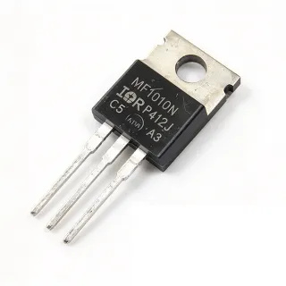
IRFB7534PBF - 60V 195A StrongIRFET N-Channel MOSFET | Infineon
MPN: IRFB7534PBF ✓ Hoạt độngIRFB7534PBF Tóm tắt
A power MOSFET is a voltage-controlled three-terminal switch that conducts current between drain and source when a sufficient gate-to-source voltage is applied. Within the broader taxonomy, the IRFB7534PBF sits at: N-channel MOSFET → power MOSFET → discrete semiconductor → power management building block. The TO-220AB package places it in the through-hole, single-die, three-pin family (TO-220 family → THT discrete semiconductor → JEDEC-recognized outline). The "PbF" suffix indicates lead-free (Pb-free) terminal finish compliant with RoHS.
Key features include an ultra-low on-state resistance of 2.4 mΩ max, low gate charge for fast switching, an avalanche-rated body diode for unclamped inductive switching, and a logic-level-friendly threshold that drives cleanly from standard 10 V gate drive. The TO-220AB's metal tab doubles as a heatsink mount, and the device is qualified to MSL1 (unlimited floor life) for simplified handling.
Built on Infineon's StrongIRFET™ planar process, the IRFB7534PBF balances low conduction loss with robust short-circuit-withstand capability. The 195 A continuous rating (case-referenced) is de-rated by PCB layout and heatsinking; designers must use the thermal resistance curve to size the heatsink for their specific load profile.
Typical applications include brushed and BLDC motor drives, battery protection and switching, low-voltage DC-DC converter high-side switches, e-bike and power-tool controllers, and high-current load switches in 24 V/48 V industrial rails.
When designing with this MOSFET, ensure the gate driver delivers at least 10 V VGS for full enhancement and consider a gate-source pull-down resistor (10 kΩ) to prevent inadvertent turn-on from Miller capacitance during high dV/dt events.
This page synthesizes distributor pricing, drop-in alternatives, and practical design notes not found in the manufacturer datasheet, giving engineers a one-stop reference for part selection, sourcing, and PCB implementation.
Bộ thay thế dễ dàng lắp đặt cho IRFB7534PBF — cùng gói, chân-to-chân tương thích. Các bộ phận yêu cầu hàn PCB bị loại trừ.
Các biến thể trong loạt này
Các mẫu cùng loạt có thể lắp đặt dễ dàng tương thích với IRFB7534PBF (cùng hình factor và footprint) — khác nhau ở Technology, Package, RoHS Status, FET Type.
IRFB7530PBF
✅ Drop-In📋 Tham chiếu thay thế (không có trong danh mục)
IRFB3006PBF
✅ Drop-In📋 Tham chiếu thay thế (không có trong danh mục)
IRFB52N15DPBF
✅ Drop-In ⚠️ Thông số chưa được xác minhLiên hệ để biết giá
Xem tài liệu →STP75NF75
✅ Drop-In📋 Tham chiếu thay thế (không có trong danh mục)
FDB047N10
✅ Drop-In📋 Tham chiếu thay thế (không có trong danh mục)
IRFB7534PBF Tỷ lệ tối đa & tính chất điện
| Manufacturer | Infineon Technologies |
| Part Number | IRFB7534PBF |
| Technology | StrongIRFET™ (planar N-channel) |
| Kiểu transitor | N-Channel MOSFET |
| Drain-Source Voltage (VDS) max | 60 V |
| Continuous Drain Current (ID) at Tc=25C | 195 A |
| Power Dissipation (PD) at Tc=25C | 294 W |
| On-Resistance RDS(on) max at VGS=10V | 2.4 mOhm |
| Gate Threshold Voltage VGS(th) | 3.7 V (typ) |
| Avalanche Energy Rated | Yes |
| Hộp | TO-220AB |
| Kiểu lắp đặt | Through Hole |
| Khoảng nhiệt độ hoạt động | -55C to +175C |
| Trạng thái RoHS | Compliant (PbF suffix) |
| Cấp MSL | MSL1 (unlimited floor life) |
Cấu hình chân IRFB7534PBF
| Chân 1 | Gate — Gate control input; drive to 10V for full enhancement |
| Chân 2 | Drain — Drain terminal; connected to load high side |
| Chân 3 | Source — Source terminal; reference for gate drive and load return |
Khu vực hoạt động an toàn (SOA) - DC
Ứng dụng tiêu biểu
IRFB7534PBF phù hợp cho 6 Áp dụngs: Brushed DC Motor Drive, BLDC Motor Drive (3-Phase Inverter), Battery Protection and Switching, Synchronous Rectifier in DC-DC Converters, E-Bike and Power Tool Controllers, Industrial 24V Load Switch.
Brushed DC Motor Drive
The IRFB7534PBF's 2.4 mΩ RDS(on) and 195 A continuous drain current make it an excellent low-side switch in brushed DC motor H-bridge drives. With VDS rated to 60 V it covers 12 V and 24 V battery rails with substantial avalanche headroom for inductive kickback at PWM turn-off. The TO-220AB package bolts directly to a chassis or aluminum heatsink, dissipating the P = I²R conduction loss (e.g., 24 W at 100 A) without requiring forced-air cooling. Place the MOSFET in the low-side position with a gate driver delivering 10-12 V VGS, and add a 10 kΩ gate-source pull-down to prevent Miller-effect turn-on during the high-side FET's switching transitions. Typical use cases include power tools, e-bike controllers, and automotive accessory motors.
Được đề xuất
BLDC Motor Drive (3-Phase Inverter)
In a 3-phase brushless DC motor inverter, the IRFB7534PBF serves as both the high-side and low-side switch in each half-bridge leg, forming a six-MOSFET topology driven by a 3-phase gate-driver IC. Its 2.4 mΩ RDS(on) minimizes conduction loss during the 120-degree commutation intervals, while the 195 A rating handles the high inrush during motor startup and direction reversal. The StrongIRFET™ technology provides robust short-circuit withstand, critical when a winding fault momentarily pulls the MOSFET into its saturation region. Pair with an IRS2302STRPBF or IR2114SSTRPBF gate driver for bootstrap high-side drive, and use a current-sense resistor or shunt in the DC-link return to feed the FOC algorithm.
Được đề xuất
Battery Protection and Switching
The IRFB7534PBF functions as a low-side disconnect switch in 12 V, 24 V, and 48 V battery management systems, where its low 2.4 mΩ RDS(on) keeps steady-state voltage drop under 50 mV even at 20 A continuous load - critical for accurate fuel-gauging. Its 195 A peak rating handles the inrush of capacitive loads such as inverters and motor controllers. The avalanche-rated body diode absorbs the back-EMF when switching off inductive battery loads. Place it in series with the battery negative terminal, gate-pulled-up through a 100 kΩ resistor to the battery, and driven low by an NPN transistor or gate driver controlled by the BMS microcontroller. The TO-220AB package simplifies hand-soldered assembly for prototype battery packs.
Được đề xuất
Synchronous Rectifier in DC-DC Converters
As the synchronous rectifier (low-side) MOSFET in a buck converter, the IRFB7534PBF replaces a Schottky diode and reduces rectifier loss from ~0.5 V to ~0.01 V (I x RDS(on)). At 50 A load and 12 V to 3.3 V conversion, this saves roughly 25 W of dissipation and improves overall converter efficiency by 3-5%. The 60 V VDS comfortably handles 24 V industrial bus voltages after derating. Drive the gate from the controller's synchronous-rectifier output through a gate-driver IC, and ensure the dead-time is short (30-50 ns) to minimize body-diode conduction loss. The StrongIRFET™ avalanche rating absorbs ringing on the switch node at turn-off.
Được đề xuất
E-Bike and Power Tool Controllers
E-bike traction controllers and cordless power-tool motor drivers benefit from the IRFB7534PBF's combination of low RDS(on) and high peak-current capability. A typical 36 V / 250 W e-bike controller running at 15 A continuous sees only ~0.5 W of conduction loss per MOSFET, allowing the controller to fit in a small sealed aluminum housing without active cooling. The 60 V VDS rating provides 24 V of margin above the 36 V nominal battery, tolerating regen braking transients. In power-tool applications, the 195 A rating supports the 5-10x inrush spike when the motor starts under load. TO-220AB's tab mounts directly to the controller housing for effective passive cooling.
Được đề xuất
Industrial 24V Load Switch
In 24 V industrial control systems, the IRFB7534PBF acts as a high-current load switch for solenoids, relays, heaters, and motor loads. Its 60 V VDS rating covers the 24 V nominal rail with full margin for transients on long inductive cables (per IEC 61131-2 industrial automation standards). The 195 A continuous rating allows it to switch multi-kW loads directly without pre-driver stages. Drive the gate from a PLC output or isolated gate driver through a 100 Ω gate resistor to control dV/dt and limit ringing. The TO-220AB package is the de-facto industrial standard for panel-mount and DIN-rail power modules, simplifying mechanical integration.
Được đề xuất
Tóm tắt các sản phẩm được đề xuất
Dữ liệu tham khảo kỹ thuật cho IRFB7534PBF — so sánh, hướng dẫn thiết kế và thông tin tuân thủ.
Hướng dẫn chọn lựa
So sánh với các sản phẩm thay thế
| Tham số | Sản phẩm này | IRFB7530PBF | IRFB3006PBF | IRFB52N15DPBF | STP75NF75 | FDB047N10 |
|---|---|---|---|---|---|---|
| Package | TO-220AB | TO-220AB (same) | TO-220AB (same) | TO-220AB (same) | TO-220AB (same) | TO-220AB (same) |
| Brand | Infineon Technologies | Infineon Technologies | Infineon Technologies | Infineon Technologies | STMicroelectronics | onsemi |
| VDS max | 60 V | 60 V | 60 V | 150 V | 75 V | 100 V |
| Continuous Drain Current (Tc=25C) | 195 A | 195 A | 195 A | 51 A | 75 A | 120 A |
| RDS(on) max @ VGS=10V | 2.4 mOhm | 3.3 mOhm | 2.5 mOhm | 32 mOhm | 11 mOhm | 4.7 mOhm |
| Power Dissipation (Tc=25C) | 294 W | 294 W | 294 W | 330 W | 300 W | 260 W |
| Technology | StrongIRFET planar | StrongIRFET planar | StrongIRFET planar | StrongIRFET planar | STripFET | PowerTrench |
| RoHS Compliant | Yes (PbF) | Yes (PbF) | Yes (PbF) | Yes (PbF) | Yes | Yes |
Bảo phân biệt quan trọng
- Lowest RDS(on) in the 60V TO-220AB StrongIRFET family (vsIRFB7530PBF)
- Higher voltage rating than 60V-class competitors (vsIRFB3006PBF)
- Higher peak current handling vs higher-voltage Infineon parts (vsIRFB52N15DPBF)
- Stronger current rating vs cross-brand equivalents (vsSTP75NF75)
Ghi chú thiết kế
The IRFB7534PBF is rated 294 W at Tc=25C, but this assumes infinite heatsink on the case. In practice, with a typical TO-220AB junction-to-ambient thermal resistance of 62 C/W (no heatsink) or 30 C/W (small clip-on heatsink), continuous dissipation is limited to roughly 2-4 W before the junction approaches 150C. For high-current switching applications, use a TO-220-specific extruded aluminum heatsink with thermal grease and a clip; aim for case-to-ambient resistance below 5 C/W to handle 100+ A continuous loads.
Minimize the drain-source loop inductance by placing the MOSFET directly on the bus capacitor with the shortest possible lead/trace length. Use a 1-10 Ω gate resistor to dampen ringing, and add a 10 kΩ gate-source pull-down resistor to prevent Miller-effect turn-on during high dV/dt switching events. The TO-220 leads should be trimmed to ~5 mm above the PCB to reduce lead inductance and radiated EMI.
Do not exceed 60 V on the drain even transiently - inductive kickback from motor or relay loads can exceed VDS within microseconds. Add a flyback diode or TVS across inductive loads, and ensure VGS never exceeds ±20 V (use a Zener clamp on the gate if driving from a higher-voltage source). The body diode is avalanche-rated but not designed for sustained rectification above a few amps; use an external Schottky or synchronous-rectifier MOSFET for high-frequency switching applications.
Thông tin tuân thủ
PbF suffix confirms lead-free (Pb-free) plating per Infineon datasheet. RoHS compliant. Not AEC-Q100 qualified - use IPP/IBS-series parts for automotive. MSL1 rated.