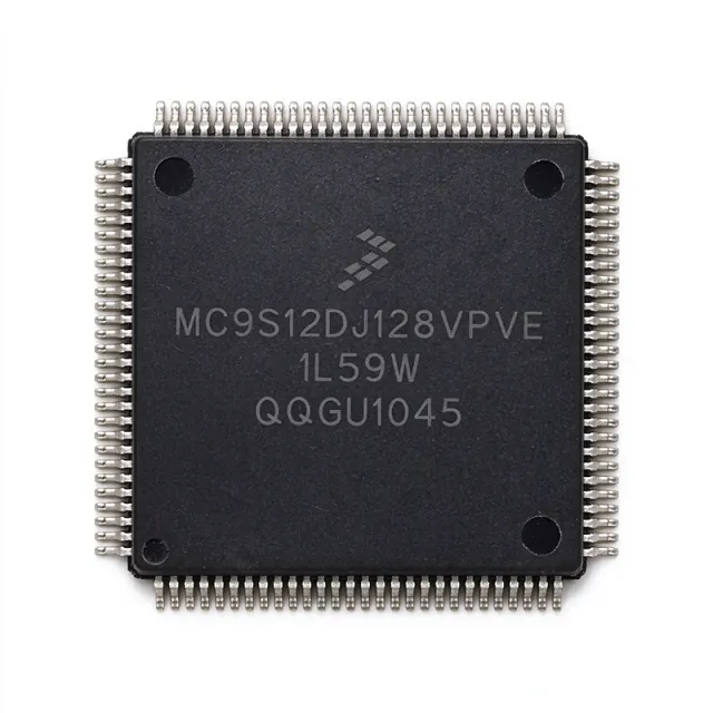
MC9S12DJ128CPVE - HCS12 16-bit MCU, 128KB Flash, 112-LQFP | NXP
MPN: MC9S12DJ128CPVE ✗ Cuối đờiMC9S12DJ128CPVE Tóm tắt
A 16-bit microcontroller (MCU) is a programmable processor with an internal data path of 16 bits, providing a balance between the simplicity of 8-bit devices and the computational throughput of 32-bit cores. Within the broader taxonomy, the MC9S12DJ128CPVE sits under HCS12 -> 16-bit MCU -> microcontroller -> embedded processor -> semiconductor. It is widely used in automotive body electronics, industrial control, and consumer appliances where deterministic real-time response, on-chip analog peripherals, and CAN connectivity are valued.
Key features include two asynchronous serial communications interfaces (SCI), two synchronous serial peripheral interfaces (SPI), one Inter-IC (I2C) bus interface, an 8-channel IC/OC enhanced capture timer, two 8-channel 10-bit analog-to-digital converters (ADC), an 8-channel pulse-width modulator (PWM), and 20 discrete digital I/O lines. The HCS12 core integrates the standard S12 instruction set with background debug mode (BDM) and on-chip interrupt control.
The architecture combines a 16-bit RISC-like programming model with a rich set of mixed-signal peripherals. The dual 10-bit ADC, 8-channel PWM, and CAN-compatible timers enable the part to replace multiple external components in motor-control and sensor-interface designs. System resource mapping, clock generation, interrupt control, and bus interfacing are all handled on-chip, simplifying board layout.
Typical applications include automotive body controllers, HVAC control modules, instrument clusters, industrial CAN nodes, and battery management peripherals. Its wide operating voltage range and automotive temperature grade make it suitable for under-hood and chassis deployments, while the LQFP-112 footprint allows conventional SMT assembly.
When designing with the MC9S12DJ128CPVE, engineers should review the NRND notice on the NXP product page and plan a migration path. The S12X and S12 MagniV families offer pin-compatible successors with additional memory and CAN FD support. Verify supply-chain availability before committing to new designs.
Bộ thay thế dễ dàng lắp đặt cho MC9S12DJ128CPVE — cùng gói, chân-to-chân tương thích. Các bộ phận yêu cầu hàn PCB bị loại trừ.
Các biến thể trong loạt này
Các mẫu cùng loạt có thể lắp đặt dễ dàng tương thích với MC9S12DJ128CPVE (cùng hình factor và footprint) — khác nhau ở Package, Flash Memory, Product Type, ADC, Architecture.
MC9S12DJ128MPVE
Liên hệ để biết giá
Xem tài liệu →MC9S12DT256CPVE
Liên hệ để biết giá
Xem tài liệu →MC9S12DP512CPVE
Liên hệ để biết giá
Xem tài liệu →MC9S12DT256VPVE
Liên hệ để biết giá
Xem tài liệu →MC9S12H256VFVE
Liên hệ để biết giá
Xem tài liệu →MC9S12DJ128CPVE Tỷ lệ tối đa & tính chất điện
| Core | HCS12 |
| Bề rộng đường dữ liệu | 16 bit |
| Tần số xung maksimum | 25 MHz |
| Program Memory Size | 128 KB (128K x 8) Flash |
| Hộp | 112-LQFP (20 x 20 mm) |
| Kiểu lắp đặt | Surface Mount |
| SCI (UART) Interfaces | 2 |
| SPI Interfaces | 2 |
| I2C (Inter-IC Bus) Interfaces | 1 |
| ADC Channels | 2 x 8-channel, 10-bit |
| PWM Channels | 8 |
| Enhanced Capture Timer Channels | 8 (IC/OC) |
| Digital I/O Pins | 20 |
| Trạng thái vòng đời | NRND (Not Recommended for New Designs) |
Cấu hình chân MC9S12DJ128CPVE
| Chân 1 | TCLK — Timer clock input |
| Chân 2 | TDDR — Test / reserved signal |
| Chân 3 | BKGD — Background Debug Mode pin |
| Chân 4 | RESET — External reset input |
| Chân 5 | VDDR — Voltage regulator supply |
| Chân 6 | VDD — Digital supply voltage |
| Chân 7 | VSS — Digital ground |
| Chân 8 | VSS — Digital ground |
| Chân 9 | VDDPLL — PLL supply voltage |
| Chân 10 | VSSPLL — PLL ground |
| Chân 11 | PAD0 — Port AD bit 0 (digital I/O) |
| Chân 12 | PAD1 — Port AD bit 1 (digital I/O) |
| Chân 13 | PAD2 — Port AD bit 2 (digital I/O) |
| Chân 14 | PAD3 — Port AD bit 3 (digital I/O) |
| Chân 15 | PAD4 — Port AD bit 4 (digital I/O) |
| Chân 16 | PAD5 — Port AD bit 5 (digital I/O) |
| Chân 17 | PAD6 — Port AD bit 6 (digital I/O) |
| Chân 18 | PAD7 — Port AD bit 7 (digital I/O) |
| Chân 19 | PAD8 — Port AD bit 8 (digital I/O) |
| Chân 20 | PAD9 — Port AD bit 9 (digital I/O) |
| Chân 21 | PAD10 — Port AD bit 10 (digital I/O) |
| Chân 22 | PAD11 — Port AD bit 11 (digital I/O) |
| Chân 23 | PAD12 — Port AD bit 12 (digital I/O) |
| Chân 24 | PAD13 — Port AD bit 13 (digital I/O) |
| Chân 25 | PAD14 — Port AD bit 14 (digital I/O) |
| Chân 26 | PAD15 — Port AD bit 15 (digital I/O) |
| Chân 27 | PA0 — Port A bit 0 |
| Chân 28 | PA1 — Port A bit 1 |
| Chân 29 | PA2 — Port A bit 2 |
| Chân 30 | PA3 — Port A bit 3 |
| Chân 31 | PA4 — Port A bit 4 |
| Chân 32 | PA5 — Port A bit 5 |
| Chân 33 | PA6 — Port A bit 6 |
| Chân 34 | PA7 — Port A bit 7 |
| Chân 35 | PB0 — Port B bit 0 |
| Chân 36 | PB1 — Port B bit 1 |
| Chân 37 | PB2 — Port B bit 2 |
| Chân 38 | PB3 — Port B bit 3 |
| Chân 39 | PB4 — Port B bit 4 |
| Chân 40 | PB5 — Port B bit 5 |
| Chân 41 | PB6 — Port B bit 6 |
| Chân 42 | PB7 — Port B bit 7 |
| Chân 43 | PE0 — Port E bit 0 / IRQ |
| Chân 44 | PE1 — Port E bit 1 / IRQ |
| Chân 45 | PE2 — Port E bit 2 |
| Chân 46 | PE3 — Port E bit 3 |
| Chân 47 | PE4 — Port E bit 4 |
| Chân 48 | PE5 — Port E bit 5 |
| Chân 49 | PE6 — Port E bit 6 |
| Chân 50 | PE7 — Port E bit 7 |
| Chân 51 | PH0 — Port H bit 0 |
| Chân 52 | PH1 — Port H bit 1 |
| Chân 53 | PH2 — Port H bit 2 |
| Chân 54 | PH3 — Port H bit 3 |
| Chân 55 | PH4 — Port H bit 4 |
| Chân 56 | PH5 — Port H bit 5 |
| Chân 57 | PH6 — Port H bit 6 |
| Chân 58 | PH7 — Port H bit 7 |
| Chân 59 | PJ0 — Port J bit 0 |
| Chân 60 | PJ1 — Port J bit 1 |
| Chân 61 | PJ2 — Port J bit 2 |
| Chân 62 | PJ3 — Port J bit 3 |
| Chân 63 | PJ4 — Port J bit 4 |
| Chân 64 | PJ5 — Port J bit 5 |
| Chân 65 | PJ6 — Port J bit 6 |
| Chân 66 | PJ7 — Port J bit 7 |
| Chân 67 | PK0 — Port K bit 0 |
| Chân 68 | PK1 — Port K bit 1 |
| Chân 69 | PK2 — Port K bit 2 |
| Chân 70 | PK3 — Port K bit 3 |
| Chân 71 | PK4 — Port K bit 4 |
| Chân 72 | PK5 — Port K bit 5 |
| Chân 73 | PK6 — Port K bit 6 |
| Chân 74 | PK7 — Port K bit 7 |
| Chân 75 | PM0 — Port M bit 0 |
| Chân 76 | PM1 — Port M bit 1 |
| Chân 77 | PM2 — Port M bit 2 |
| Chân 78 | PM3 — Port M bit 3 |
| Chân 79 | PM4 — Port M bit 4 |
| Chân 80 | PM5 — Port M bit 5 |
| Chân 81 | PM6 — Port M bit 6 |
| Chân 82 | PM7 — Port M bit 7 |
| Chân 83 | PS0 — Port S bit 0 (SPI1) |
| Chân 84 | PS1 — Port S bit 1 (SPI1) |
| Chân 85 | PS2 — Port S bit 2 (SPI1) |
| Chân 86 | PS3 — Port S bit 3 (SPI1) |
| Chân 87 | PS4 — Port S bit 4 (SPI0) |
| Chân 88 | PS5 — Port S bit 5 (SPI0) |
| Chân 89 | PS6 — Port S bit 6 (SPI0) |
| Chân 90 | PS7 — Port S bit 7 (SPI0) |
| Chân 91 | PT0 — Port T bit 0 (TIM channel) |
| Chân 92 | PT1 — Port T bit 1 (TIM channel) |
| Chân 93 | PT2 — Port T bit 2 (TIM channel) |
| Chân 94 | PT3 — Port T bit 3 (TIM channel) |
| Chân 95 | PT4 — Port T bit 4 (TIM channel) |
| Chân 96 | PT5 — Port T bit 5 (TIM channel) |
| Chân 97 | PT6 — Port T bit 6 (TIM channel) |
| Chân 98 | PT7 — Port T bit 7 (TIM channel) |
| Chân 99 | VDDX — I/O supply voltage |
| Chân 100 | VSSX — I/O ground |
| Chân 101 | CAN_TXCAN — CAN transmit output (msCAN module) |
| Chân 102 | CAN_RXCAN — CAN receive input (msCAN module) |
| Chân 103 | TXD0 — SCI0 transmit |
| Chân 104 | RXD0 — SCI0 receive |
| Chân 105 | TXD1 — SCI1 transmit |
| Chân 106 | RXD1 — SCI1 receive |
| Chân 107 | SDA — I2C serial data |
| Chân 108 | SCL — I2C serial clock |
| Chân 109 | XCLKS — Crystal oscillator select |
| Chân 110 | EXTAL — External crystal/clock input |
| Chân 111 | XTAL — Crystal oscillator output |
| Chân 112 | TEST — Test mode pin (pull low for normal operation) |
Ứng dụng tiêu biểu
MC9S12DJ128CPVE phù hợp cho 7 Áp dụngs: Automotive Body Control Module, HVAC Control Module, Instrument Cluster Controller, Industrial CAN Node, Battery Management Peripheral, Motor Control / Pump Driver, Appliance Control Board.
Automotive Body Control Module
The NXP MC9S12DJ128CPVE fits automotive body-control applications because it integrates dual 8-channel 10-bit ADCs, an 8-channel PWM, and CAN-compatible timers in a single 16-bit HCS12 core running at 25 MHz. Body modules typically read multiple sensor inputs (door switches, lighting sensors, temperature), drive PWM-controlled loads (motors, lamps, mirrors), and communicate over CAN, all of which the MC9S12DJ128CPVE handles without external glue logic. With 128 KB Flash it accommodates typical BCM firmware including diagnostic routines per UDS/KWP2000, while the 112-LQFP footprint supports SMT assembly on production PCBs. Engineers designing BCMs should plan migration paths to S12X or S12 MagniV successors because this part is now NRND, but existing programs can continue using it as long as inventory holds.
Được đề xuất
HVAC Control Module
Automotive HVAC modules demand precise PWM control of blower motors and mix doors plus reliable analog sensing of cabin temperature. The MC9S12DJ128CPVE's 8-channel PWM block drives servo and brushed-motor actuators while its dual 10-bit ADC samples thermistor, humidity, and pressure sensors concurrently. The HCS12 core at 25 MHz delivers deterministic interrupt response needed for closed-loop temperature control, and 128 KB Flash holds look-up tables, PID control loops, and CAN stack for HVAC network communication. Because HVAC units operate across -40C to +85C ambient, the part's automotive temperature grade is suitable. The 112-LQFP package allows efficient PCB layout with thermal vias under the exposed pad to dissipate quiescent heat.
Được đề xuất
Instrument Cluster Controller
Instrument clusters require real-time stepper or DC motor control for analog gauges, plus CAN/LIN communication with the vehicle network. The MC9S12DJ128CPVE offers the 16-bit HCS12 core at 25 MHz with 8-channel PWM for gauge drive and dual 10-bit ADCs for fuel-level and temperature sensing. Its 20 digital I/O lines handle keypad inputs, indicator LEDs, and backlight dimming via PWM. 128 KB Flash accommodates gauge calibration tables, odometer storage in EEPROM, and the CAN/LIN stack. The 112-LQFP package provides sufficient pin count for stepper motor phases, display driver interfaces, and diagnostic LEDs.
Được đề xuất
Industrial CAN Node
The MC9S12DJ128CPVE serves as a CAN node in industrial automation networks where deterministic real-time response and on-chip analog peripherals are valued. Its HCS12 core at 25 MHz handles CANopen or DeviceNet protocol stacks, while the dual 10-bit ADC samples 4-20 mA industrial sensors through current-sense resistors. The 8-channel PWM can drive proportional valves or solid-state relays, and 128 KB Flash holds stack libraries plus application logic. SPI and I2C peripherals connect to external ADCs, DACs, or EEPROM for data logging. The 112-LQFP is industrial-standard surface-mount footprint compatible with pick-and-place assembly.
Được đề xuất
Battery Management Peripheral
Battery management systems (BMS) require multiple ADC channels for cell voltage and current sensing, plus CAN communication with the vehicle or pack controller. The MC9S12DJ128CPVE's dual 8-channel 10-bit ADC can sample up to 16 cell voltages with external muxing, while the 8-channel PWM drives cell-balancing FETs. The HCS12 core at 25 MHz handles SOC/SOH algorithms and CAN diagnostics within 128 KB Flash. Its automotive temperature grade supports under-hood deployment. The 112-LQFP package accommodates all analog, PWM, and CAN signals with proper grounding.
Được đề xuất
Motor Control / Pump Driver
DC and BLDC pump motors in automotive and industrial settings benefit from the MC9S12DJ128CPVE's 8-channel PWM block with complementary outputs and dead-time insertion, plus dual 10-bit ADC channels for current sensing via shunt resistors. The HCS12 core at 25 MHz runs field-oriented control (FOC) algorithms at adequate update rates for small motors. The 128 KB Flash holds motor-control firmware, fault handling, and CAN diagnostics. Integrated SCI, SPI, and I2C simplify communication with external gate drivers and position sensors. The 112-LQFP provides enough pins for three-phase signals plus encoder inputs.
Được đề xuất
Appliance Control Board
White goods and small appliances use the MC9S12DJ128CPVE as a single-chip controller combining user-interface key scanning, sensor acquisition, motor/valve actuation, and display driving. The 16-bit HCS12 core at 25 MHz handles UI state machines, while the dual 10-bit ADC reads temperature, humidity, or weight sensors. The 8-channel PWM drives pumps, valves, and buzzer tones. The two SCI (UART) channels can interface with wireless modules or external displays. The 112-LQFP package supports SMT assembly in cost-sensitive consumer designs.
Được đề xuất
Tóm tắt các sản phẩm được đề xuất
Dữ liệu tham khảo kỹ thuật cho MC9S12DJ128CPVE — so sánh, hướng dẫn thiết kế và thông tin tuân thủ.
Hướng dẫn chọn lựa
So sánh với các sản phẩm thay thế
| Tham số | Sản phẩm này | MC9S12DJ128MPVE | MC9S12DT256CPVE | MC9S12DP512CPVE | MC9S12DT256VPVE | MC9S12H256VFVE |
|---|---|---|---|---|---|---|
| Brand | NXP Semiconductors | NXP Semiconductors | NXP Semiconductors | NXP Semiconductors | NXP Semiconductors | NXP Semiconductors |
| Package | 112-LQFP (20x20) | 112-LQFP (20x20) - same | 112-LQFP (20x20) - same | 112-LQFP (20x20) - same | 112-LQFP (20x20) - same | 112-LQFP (20x20) - same |
| Core | HCS12, 16-bit | HCS12, 16-bit | HCS12, 16-bit | HCS12, 16-bit | HCS12, 16-bit | HCS12, 16-bit |
| Flash Memory | 128 KB | 128 KB | 256 KB | 512 KB | 256 KB | 256 KB |
| Max Clock Frequency | 25 MHz | 25 MHz | 25 MHz | 25 MHz | 25 MHz | 25 MHz |
| PWM Channels | 8 | 8 | 8 | 8 | 8 | 8 |
| ADC | 2 x 8-channel 10-bit | 2 x 8-channel 10-bit | 2 x 8-channel 10-bit | 2 x 8-channel 10-bit | 2 x 8-channel 10-bit | 2 x 8-channel 10-bit |
| Lifecycle Status | NRND | NRND | Active | Active | NRND | Active |
Bảo phân biệt quan trọng
- HCS12 16-bit core with dual 10-bit ADC and 8-channel PWM (vsMC9S12H256VFVE)
- Lower Flash footprint reduces cost and silicon area (vsMC9S12DP512CPVE)
- Dual SCI plus SPI/I2C for multi-bus connectivity (vsMC9S12DT256VPVE)
Ghi chú thiết kế
The MC9S12DJ128CPVE integrates an on-chip voltage regulator with VDDR/VDDX pins. Decouple VDD with a 100 nF ceramic plus a 4.7 uF bulk capacitor placed within 5 mm of the supply pins; add separate 100 nF decoupling on each AVDD/VDDPLL pair. If using the internal regulator, drive VDDR from a clean 5 V source; for low-noise analog applications, consider external LDO for ADC supply rails.
Although the 112-LQFP package has moderate thermal resistance (theta_JA approximately 50 C/W on a 4-layer JEDEC board), sustained 25 MHz operation plus active ADC and PWM can push junction temperature close to the 125 C limit in enclosed automotive modules. Add thermal vias under the central thermal pad and route ground pour on the top layer to spread heat. Derate clock frequency if the enclosure ambient exceeds 85 C.
Place the external crystal within 10 mm of EXTAL/XTAL with symmetric traces and a ground guard ring; keep ADC traces away from PWM and digital switching signals to minimize coupling. Route the BKGD pin to a dedicated debug header with a 4.7 kohm pull-up to VDDX. The CAN TXCAN/RXCAN pair should be routed as a 100-ohm differential pair with ground shielding for reliable bus operation.
Because the part is NRND, do not start new automotive production designs without an explicit last-time-buy plan and a verified successor on the S12X or S12 MagniV families. When migrating to the MC9S12DT256CPVE or MC9S12DP512CPVE, re-validate linker scripts and interrupt vector tables because the larger Flash maps are slightly different. Verify BDM probe compatibility - some older P&E Micro cables require firmware updates for newer mask sets.
Thông tin tuân thủ
Compliance status not explicitly stated in distributor listings retrieved 2026-10-20; verify against the NXP product declaration before RoHS/REACH-bound design.


