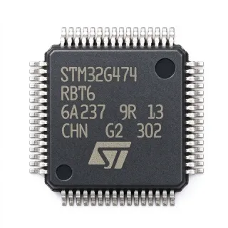
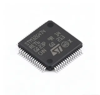
SPC560P34L1CEFAY - 32-bit Auto Chassis MCU, 64MHz, 192KB Flash LQFP-64
MPN: SPC560P34L1CEFAY ✓ Hoạt độngSPC560P34L1CEFAY Tóm tắt
Background: A 32-bit automotive microcontroller is an MCU whose instruction set, peripherals, and qualification pedigree target body and chassis domains rather than infotainment or ADAS. Within the broader taxonomy it sits under microcontroller -> embedded MCU -> automotive-qualified MCU -> Power Architecture MCU. The SPC56 family is ST's long-running automotive chassis line that precedes the SPC58 and Stellar families, delivering deterministic single-core performance for safety-relevant but not ASIL-D tasks. Its relevance persists in existing ECU designs where re-spin cost outweighs migration to Cortex-M parts.
Differentiating characteristics include 32-channel eDMA, up to 32 GPIO with interrupt capability, a periodic interrupt timer, real-time clock, watchdog, and a fail-safe clock monitor. The integrated FlexCAN supports up to 6 mailboxes with CAN 2.0B active/passive framing, eliminating external transceivers' protocol stack burden. Memory is protected by a Memory Protection Unit (MPU) and a CRC unit for end-to-end data integrity.
Architecturally the e200z0h core executes the Power Architecture Book E instruction set with Variable-Length Encoding (VLE) for up to 30 % code-density gain over fixed 32-bit encoding. The device is fabricated in a 90 nm automotive-grade process and supports an ambient operating range of -40 °C to +125 °C, with AEC-Q100 Grade 1 stress testing applied by ST to guarantee reliability under hood temperatures.
Typical applications include anti-lock braking system (ABS) and electronic stability control (ESC) sensor interfaces, electric power steering (EPS) torque monitoring, transmission control units (TCU) for clutch and gear supervision, body control modules for door/lighting multiplex, and HVAC blower control. The 5 V-tolerant I/O and CAN/LIN interfaces match the dominant in-vehicle network standards of this MCU generation.
Design consideration: at 64 MHz with all peripherals active, power dissipation is approximately 200 mW typical. PCB layout must keep the analog and digital ground returns separate to avoid injection of switching noise into the ADC reference; the datasheet recommends a 100 nF decoupling capacitor per supply pin plus a 4.7 µF bulk on each main rail.
Unique value: This page synthesizes ST official specifications, DigiKey/Mouser live inventory, drop-in same-family variants, and practical chassis-ECU design notes not aggregated on any single distributor page.
Bộ thay thế dễ dàng lắp đặt cho SPC560P34L1CEFAY — cùng gói, chân-to-chân tương thích. Các bộ phận yêu cầu hàn PCB bị loại trừ.
Các biến thể trong loạt này
Các mẫu cùng loạt có thể lắp đặt dễ dàng tương thích với SPC560P34L1CEFAY (cùng hình factor và footprint) — khác nhau ở Package, Communication Interfaces, Core, Core Architecture, Operating Temperature Range.
SPC560P34L1CEFAR
✅ Drop-InLiên hệ để biết giá
Xem tài liệu →SPC560P34L1CEFAX
✅ Drop-In📋 Tham chiếu thay thế (không có trong danh mục)
SPC560P34L1BEAAY
✅ Drop-In ⚠️ Thông số chưa được xác minh📋 Tham chiếu thay thế (không có trong danh mục)
SPC560P40L1CEFAR
✅ Drop-InLiên hệ để biết giá
Xem tài liệu →SPC560P50L1CEFAR
✅ Drop-In ⚠️ Thông số chưa được xác minh📋 Tham chiếu thay thế (không có trong danh mục)
SPC560P34L1CEFAY Tỷ lệ tối đa & tính chất điện
| Core | e200z0h (Power Architecture, VLE) |
| Architecture | 32-bit RISC |
| Maximum CPU Frequency | 64 MHz |
| Program Flash Memory | 192 KB (192K x 8) |
| SRAM | 14 KB |
| Điện áp cung cấp | 3.0 V to 5.5 V (5 V typical) |
| I/O Voltage Tolerance | 5 V |
| ADC | 2 x 12-bit SAR, up to 32 channels |
| CAN | 1 x FlexCAN (CAN 2.0B) |
| LIN/SPI/UART | LINFlex, DSPI, UART/USART |
| DMA | 32 channels (eDMA) |
| GPIO | Up to 32 (interrupt-capable) |
| Timers | eMIOS, PIT, RTC, SWT watchdog |
| Khoảng nhiệt độ hoạt động | -40 C to +125 C |
| Hộp | 64-pin LQFP (10x10 mm) |
| Kiểu lắp đặt | Surface Mount |
| AEC-Q100 | Qualified (Grade 1 family) |
| Trạng thái RoHS | Compliant |
Cấu hình chân SPC560P34L1CEFAY
| Chân 1 | VDD_HV — High-voltage supply (3.0-5.5 V) |
| Chân 2 | VDD_HV — High-voltage supply |
| Chân 3 | VSS_HV — High-voltage ground |
| Chân 4 | VDD_LV — Low-voltage core supply (1.2 V from internal regulator) |
| Chân 5 | VSS_LV — Low-voltage core ground |
| Chân 6 | VREF_H — ADC high reference |
| Chân 7 | VREF_L — ADC low reference |
| Chân 8 | AN0 — Analog input 0 / ANP0 / ANP8 alternate |
| Chân 9 | AN1 — Analog input 1 / ANP1 / ANP9 alternate |
| Chân 10 | AN2 — Analog input 2 / ANP2 / ANP10 alternate |
| Chân 11 | AN3 — Analog input 3 / ANP3 / ANP11 alternate |
| Chân 12 | AN4 — Analog input 4 / ANP4 / ANP12 alternate |
| Chân 13 | AN5 — Analog input 5 / ANP5 / ANP13 alternate |
| Chân 14 | AN6 — Analog input 6 / ANP6 / ANP14 alternate |
| Chân 15 | AN7 — Analog input 7 / ANP7 / ANP15 alternate |
| Chân 16 | VSS_HV — High-voltage ground |
| Chân 17 | VDD_HV — High-voltage supply |
| Chân 18 | CAN_TX — FlexCAN transmit output |
| Chân 19 | CAN_RX — FlexCAN receive input |
| Chân 20 | GPIO0 — General-purpose I/O / SIU.PCR controlled |
| Chân 21 | GPIO1 — General-purpose I/O |
| Chân 22 | GPIO2 — General-purpose I/O |
| Chân 23 | GPIO3 — General-purpose I/O |
| Chân 24 | GPIO4 — General-purpose I/O |
| Chân 25 | GPIO5 — General-purpose I/O |
| Chân 26 | GPIO6 — General-purpose I/O |
| Chân 27 | GPIO7 — General-purpose I/O |
| Chân 28 | GPIO8 — General-purpose I/O |
| Chân 29 | GPIO9 — General-purpose I/O |
| Chân 30 | GPIO10 — General-purpose I/O |
| Chân 31 | GPIO11 — General-purpose I/O |
| Chân 32 | GPIO12 — General-purpose I/O |
| Chân 33 | GPIO13 — General-purpose I/O |
| Chân 34 | GPIO14 — General-purpose I/O |
| Chân 35 | GPIO15 — General-purpose I/O |
| Chân 36 | VSS_HV — High-voltage ground |
| Chân 37 | VDD_HV — High-voltage supply |
| Chân 38 | LIN_TX — LINFlex transmit output |
| Chân 39 | LIN_RX — LINFlex receive input |
| Chân 40 | SPI_MOSI — DSPI master-out slave-in |
| Chân 41 | SPI_MISO — DSPI master-in slave-out |
| Chân 42 | SPI_SCK — DSPI serial clock |
| Chân 43 | SPI_CS0 — DSPI chip select 0 |
| Chân 44 | UART_TX — LINFlex / UART transmit |
| Chân 45 | UART_RX — LINFlex / UART receive |
| Chân 46 | JTAG_TMS — Boundary-scan mode select |
| Chân 47 | JTAG_TCK — Boundary-scan clock |
| Chân 48 | JTAG_TDO — Boundary-scan data out |
| Chân 49 | JTAG_TDI — Boundary-scan data in |
| Chân 50 | RESET — External reset, active-low |
| Chân 51 | EXTAL — External crystal / oscillator input |
| Chân 52 | XTAL — Crystal drive output |
| Chân 53 | CLKOUT — System clock output |
| Chân 54 | EIRQ0 — External interrupt request 0 |
| Chân 55 | EIRQ1 — External interrupt request 1 |
| Chân 56 | VSS_HV — High-voltage ground |
| Chân 57 | VDD_HV — High-voltage supply |
| Chân 58 | AN8 — Analog input 8 |
| Chân 59 | AN9 — Analog input 9 |
| Chân 60 | AN10 — Analog input 10 |
| Chân 61 | AN11 — Analog input 11 |
| Chân 62 | AN12 — Analog input 12 |
| Chân 63 | AN13 — Analog input 13 |
| Chân 64 | AN14 — Analog input 14 / VREF input alternate |
Ứng dụng tiêu biểu
SPC560P34L1CEFAY phù hợp cho 6 Áp dụngs: Anti-lock Braking System (ABS) ECU, Electronic Power Steering (EPS) Torque Sensor Interface, Transmission Control Unit (TCU) Clutch Actuator, Body Control Module (BCM) Lighting Multiplexing, HVAC Blower and Actuator Control, Industrial CAN-Based Sensor Hub.
Anti-lock Braking System (ABS) ECU
The SPC560P34L1CEFAY's 64 MHz deterministic single-core plus FlexCAN and 12-bit SAR ADC deliver closed-loop wheel-speed control under hard real-time constraints. With <10 µs interrupt latency and DMA-driven ADC sampling, the device reads 4 wheel-speed sensors and dispatches pressure-modulator commands within a <1 ms ABS cycle. Its AEC-Q100 Grade 1 qualification and -40 °C to +125 °C ambient rating match underhood ECU placement, while 192 KB Flash holds application firmware plus diagnostics stack with room for parameter refresh.
Được đề xuất
Electronic Power Steering (EPS) Torque Sensor Interface
EPS torque sensors require low-latency ADC sampling of redundant analog channels; the SPC560P34L1CEFAY provides dual 12-bit SAR ADCs (up to 32 channels) plus eDMA for non-blocking double-buffered acquisition. The FlexCAN interface connects to the vehicle CAN-FD backbone (CAN 2.0B fallback). The e200z0h core executes VLE-encoded safety logic with deterministic <5 µs response, fitting ASIL-A functional-safety targets when paired with a watchdog coprocessor. 64-pin LQFP fits column-mounted ECU geometry, and the 5 V I/O tolerance interfaces directly to legacy analog torque-sensor ICs without level shifters.
Được đề xuất
Transmission Control Unit (TCU) Clutch Actuator
TCU clutches need synchronized solenoid drivers linked to engine RPM, gear, and driver-demand inputs. The SPC560P34L1CEFAY's UART/USART interfaces to engine ECM while its LINFlex controls per-clutch LIN actuators. The 32-channel eDMA offloads sensor-fusion maths from the CPU, freeing CPU cycles for the solenoid-PWM generation. AEC-Q100 Grade 1 plus 14 KB SRAM provides deterministic queue depth for clutch-slip control (typical <100 µs loops), with 192 KB Flash storing calibration tables and base software.
Được đề xuất
Body Control Module (BCM) Lighting Multiplexing
BCM lighting domains typically aggregate up to 8 LED clusters and 4 LIN sub-nodes controlled from one MCU. The SPC560P34L1CEFAY's LINFlex master transceivers address each sub-node, while its GPIO banks drive PWM dimming under 1 kHz. The 192 KB Flash supports Zonal-OTA-ready bootloaders with ECC-protected signature verify; the 14 KB SRAM holds 4 LIN message buffers plus a 64-entry event log. AEC-Q100 Grade 1, 5 V I/O, and 64-pin LQFP allow drop-in reuse across distributed-node BCM layouts.
Được đề xuất
HVAC Blower and Actuator Control
HVAC modules typically combine a brushless DC blower driver, blend/flap actuators, and CAN-LIN gateway functionality. The SPC560P34L1CEFAY runs the blower commutation loop while its DSPI drives external DACs for actuator position. The temperature range of -40 °C to +125 °C supports cabin-to-engine-bay mounting variations, while the 5 V-tolerant I/O interfaces directly to cabin-mounted thermistor dividers. 192 KB Flash and 14 KB SRAM cover the calibration map of a 4-zone climate system with margin.
Được đề xuất
Industrial CAN-Based Sensor Hub
Outside automotive, the SPC560P34L1CEFAY serves industrial sensor hubs needing AEC-Q100 Grade 1 robustness with deterministic CAN dispatch. Up to 32 ADC channels digitize strain, pressure, or current sensors through 4-20 mA loops; the FlexCAN port (CAN 2.0B) participates in factory automation backbones. The 64-pin LQFP offers through-hole-style exposure for industrial test fixtures, while 192 KB Flash supports redundant pair-and-compare software for IEC 61508 SIL-1 deployments.
Được đề xuất
Tóm tắt các sản phẩm được đề xuất
Dữ liệu tham khảo kỹ thuật cho SPC560P34L1CEFAY — so sánh, hướng dẫn thiết kế và thông tin tuân thủ.
Hướng dẫn chọn lựa
So sánh với các sản phẩm thay thế
| Tham số | Sản phẩm này | SPC560P34L1CEFAR | SPC560P34L1CEFAX | SPC560P34L1BEAAY | SPC560P40L1CEFAR | SPC560P50L1CEFAR |
|---|---|---|---|---|---|---|
| Package | LQFP-64 (10x10 mm) | LQFP-64 (10x10 mm) - same | LQFP-64 (10x10 mm) - same | LQFP-64 (10x10 mm) - same | LQFP-64 (10x10 mm) - same | LQFP-64 (10x10 mm) - same |
| Brand | STMicroelectronics | STMicroelectronics | STMicroelectronics | STMicroelectronics | STMicroelectronics | STMicroelectronics |
| Flash Memory | 192 KB | 192 KB | 192 KB | 192 KB | 256 KB | 512 KB |
| SRAM | 14 KB | 14 KB | 14 KB | 14 KB | 20 KB | 32 KB |
| Maximum CPU Frequency | 64 MHz | 64 MHz | 64 MHz | 64 MHz | 64 MHz | 64 MHz |
| Core | e200z0h (32-bit Power Architecture) | e200z0h | e200z0h | e200z0h | e200z0h | e200z0h |
| CAN | 1 x FlexCAN (CAN 2.0B) | 1 x FlexCAN | 1 x FlexCAN | 1 x FlexCAN | 1 x FlexCAN | 1 x FlexCAN |
| ADC | 2 x 12-bit SAR | 2 x 12-bit SAR | 2 x 12-bit SAR | 2 x 12-bit SAR | 2 x 12-bit SAR | 2 x 12-bit SAR |
| AEC-Q100 | Qualified (Grade 1) | Qualified (Grade 1) | Qualified (Grade 1) | Qualified (Grade 1) | Qualified (Grade 1) | Qualified (Grade 1) |
| Operating Temperature | -40 C to +125 C | -40 C to +125 C | -40 C to +125 C | -40 C to +125 C | -40 C to +125 C | -40 C to +125 C |
Bảo phân biệt quan trọng
- Optimised for automotive chassis with strict determinism (vsSPC560P40L1CEFAR)
- AEC-Q100 Grade 1 with 5 V I/O tolerance (vsCortex-M0+ based automotive MCUs)
- Long product lifecycle for in-production automotive programs (vsGeneric Cortex-M0+ MCUs)
Ghi chú thiết kế
Estimated: at 64 MHz with full peripheral activity the SPC560P34L1CEFAY core draws approximately 80 mA from the internal 1.2 V regulator. ST recommends a 4.7 µF bulk plus 100 nF decoupling per VDD_HV pin and a 100 nF plus 1 µF combination on VDD_LV. Total 5 V supply current reaches approximately 60 mA typical. PCB designers should place the 4.7 µF tantalum or X7R ceramic within 10 mm of the VDD_HV pins and route the analog/digital grounds as a star under the LQFP exposed pad.
Estimated: in a 64-pin LQFP without an exposed thermal pad the thermal resistance junction-to-ambient (theta_JA) is approximately 60 C/W on a 2 oz 4-layer PCB. Continuous 60 mA * 5 V = 300 mW dissipation on a 25 C ambient lifts the junction to about 25 + (0.3 x 60) = 43 C, well below the 150 C junction limit. In sealed underhood ECUs the 125 C ambient derating gives only 1.04 W of margin; adding 2 cm² of copper pour reduces theta_JA to about 45 C/W and adds 0.7 W of margin.
Common pitfalls include: forgetting to configure VLE mode in the BAM (Boot Assist Module) before boot; mis-locating CAN_TX/RX on the wrong pins (the SPC56 P-line has only one FlexCAN routed to a single pair, not multiple); ignoring the 5 V-tolerance flag mismatch when migrating from a 3.3 V SPC58 design. The datasheet's 'Pinout' and 'Signal Multiplexing' sections are mandatory reading before PCB finalisation. Always reset the JTAG password register (JDPID) during firmware validation to avoid bricking the security lockout.
Layout recommendation: place a continuous ground plane on layer 2 with stitched vias around the LQFP perimeter (4 vias per side minimum) to provide a low-impedance return for high-speed SPI/DSPI edges. Keep the EXTAL/XTAL crystal traces under 5 mm; surround them with a guard ground ring tied to the analog ground. Route ADC analog inputs on a separate inner layer against the analog-ground reference, with no digital crossings. The 64-pin LQFP allows ample room to fan out power traces to a 4-layer stack-up while keeping the exposed-pad footprint compatible with the family's 10x10 mm common land pattern.
Thông tin tuân thủ
AEC-Q100 Grade 1 qualified per ST product page. RoHS and REACH compliant. Lead-free and halogen-free per ST packaging materials statement. Order code 'Y' suffix designates automotive grade packaging.