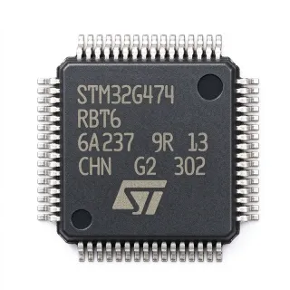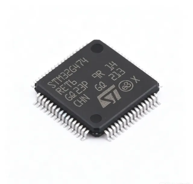
STM32G474RET6 - 170MHz Cortex-M4 MCU 512KB Flash | ST
MPN: STM32G474RET6 ✓ Hoạt độngSTM32G474RET6 Tóm tắt
A microcontroller (MCU) is a compact integrated circuit that governs a specific operation in an embedded system, integrating a processor core, memory, and programmable peripherals on a single chip. The STM32G474RET6 belongs to the STM32G4 mainstream MCU family, which sits between general-purpose MCUs and digital signal processors within the embedded-processor hierarchy, and is purpose-built for mixed-signal real-time control.
Key features include five 12-bit ADC channels with hardware oversampling (4 MSPS), four 12-bit DAC outputs, six operational amplifiers, four high-speed comparators, and the high-resolution timer (HRTIM) capable of 184 ps PWM resolution. Communication interfaces cover SPI, I2C, USART/UART, CAN FD, and USB 2.0 full-speed. CORDIC and FMAC hardware accelerators offload trigonometric and filter computations, enabling deterministic control loops with reduced CPU overhead.
Architecturally, the device pairs the Cortex-M4F core with an ART accelerator that delivers 0-wait-state flash execution, achieving maximum throughput at the rated 170 MHz clock. The embedded voltage regulator and low-power modes down to a few microamps support energy-conscious designs operating from a 1.71V to 3.6V supply.
Typical applications include field-oriented control (FOC) of brushless DC and permanent-magnet motors, digital power conversion (buck, boost, flyback), solar micro-inverters, and industrial automation. The combination of 5 MSPS-class ADC sampling, on-chip comparators, and HRTIM precision timing is decisive in these high-performance control loops.
Design consideration: keep HRTIM output traces short and routed away from analog signals, and decouple each VDD/VDDA pin with 100 nF ceramics placed as close to the IC as possible to preserve ADC accuracy.
This page synthesizes distributor pricing, drop-in alternatives, and practical design notes not found in the STMicroelectronics datasheet.
Bộ thay thế dễ dàng lắp đặt cho STM32G474RET6 — cùng gói, chân-to-chân tương thích. Các bộ phận yêu cầu hàn PCB bị loại trừ.
Các biến thể trong loạt này
Các mẫu cùng loạt có thể lắp đặt dễ dàng tương thích với STM32G474RET6 (cùng hình factor và footprint) — khác nhau ở Package, Comparators, SRAM, Flash Memory, Core.
STM32G474RET3
✅ Drop-In📋 Tham chiếu thay thế (không có trong danh mục)
STM32G474RBT6
✅ Drop-InLiên hệ để biết giá
Xem tài liệu →STM32G474CET6
✅ Drop-In ⚠️ Thông số chưa được xác minhLiên hệ để biết giá
Xem tài liệu →STM32G4A1RET6
✅ Drop-In ⚠️ Thông số chưa được xác minhLiên hệ để biết giá
Xem tài liệu →STM32G473RCT6
✅ Drop-InLiên hệ để biết giá
Xem tài liệu →GD32G474RET6
✅ Drop-In📋 Tham chiếu thay thế (không có trong danh mục)
GD32G5xx LQFP-64
✅ Drop-In📋 Tham chiếu thay thế (không có trong danh mục)
STM32G474RET6 Tỷ lệ tối đa & tính chất điện
| Core | Arm Cortex-M4F with FPU and DSP instructions |
| Tần số xung maksimum | 170 MHz |
| Performance | 213 DMIPS |
| Flash Memory | 512 KB |
| SRAM | 128 KB |
| Supply Voltage Range | 1.71 V to 3.6 V |
| Hộp | 64-pin LQFP (10x10 mm) |
| ADC | 12-bit, 5 MSPS, multiple channels |
| DAC | 12-bit, multiple channels |
| Operational Amplifiers | 6 on-chip |
| Comparators | 4 high-speed |
| High-Resolution Timer (HRTIM) | Yes, 184 ps PWM resolution |
| Hardware Accelerators | CORDIC and FMAC |
| Communication Interfaces | SPI, I2C, USART/UART, CAN FD, USB 2.0 FS |
| Khoảng nhiệt độ hoạt động | -40C to +85C (industrial) |
| Kiểu lắp đặt | Surface Mount |
| Trạng thái RoHS | Compliant |
Cấu hình chân STM32G474RET6
| Chân 1 | PB10 — GPIO B10 / HRTIM_CHC1 |
| Chân 2 | PB11 — GPIO B11 / HRTIM_CHC2 |
| Chân 3 | VSS — Digital ground |
| Chân 4 | VDD — Digital supply voltage |
| Chân 5 | PA13 — SWDIO (debug data) |
| Chân 6 | PA14 — SWCLK (debug clock) |
| Chân 7 | PA15 — GPIO A15 / HRTIM_CHB1 |
| Chân 8 | PB0 — GPIO B0 / ADC1_IN5 |
| Chân 9 | PB1 — GPIO B1 / ADC1_IN6 |
| Chân 10 | PB2 — GPIO B2 / BOOT1 |
| Chân 11 | VSS — Digital ground |
| Chân 12 | VDD — Digital supply voltage |
| Chân 13 | PA8 — GPIO A8 / HRTIM_CHA1 |
| Chân 14 | PA9 — GPIO A9 / USART1_TX |
| Chân 15 | PA10 — GPIO A10 / USART1_RX |
| Chân 16 | PA11 — GPIO A11 / USB_DM |
| Chân 17 | PA12 — GPIO A12 / USB_DP |
| Chân 18 | VSS — Digital ground |
| Chân 19 | VDD — Digital supply voltage |
| Chân 20 | VREF+ — ADC reference voltage positive |
| Chân 21 | VDDA — Analog supply voltage |
| Chân 22 | VSSA — Analog ground |
| Chân 23 | PA0 — GPIO A0 / ADC1_IN1 |
| Chân 24 | PA1 — GPIO A1 / ADC1_IN2 |
| Chân 25 | PA2 — GPIO A2 / USART2_TX |
| Chân 26 | PA3 — GPIO A3 / USART2_RX |
| Chân 27 | PA4 — GPIO A4 / DAC1_OUT1 |
| Chân 28 | PA5 — GPIO A5 / DAC1_OUT2 |
| Chân 29 | PA6 — GPIO A6 / SPI1_MISO |
| Chân 30 | PA7 — GPIO A7 / SPI1_MOSI |
| Chân 31 | PB6 — GPIO B6 / I2C1_SCL |
| Chân 32 | PB7 — GPIO B7 / I2C1_SDA |
| Chân 33 | VSS — Digital ground |
| Chân 34 | VDD — Digital supply voltage |
| Chân 35 | PB8 — GPIO B8 / CAN1_RX |
| Chân 36 | PB9 — GPIO B9 / CAN1_TX |
| Chân 37 | PB12 — GPIO B12 / SPI2_NSS |
| Chân 38 | PB13 — GPIO B13 / SPI2_SCK |
| Chân 39 | PB14 — GPIO B14 / SPI2_MISO |
| Chân 40 | PB15 — GPIO B15 / SPI2_MOSI |
| Chân 41 | PC13 — GPIO C13 (tamper) |
| Chân 42 | PC14 — GPIO C14 / OSC32_IN |
| Chân 43 | PC15 — GPIO C15 / OSC32_OUT |
| Chân 44 | VSS — Digital ground |
| Chân 45 | VDD — Digital supply voltage |
| Chân 46 | OSC_IN — HSE oscillator input |
| Chân 47 | OSC_OUT — HSE oscillator output |
| Chân 48 | NRST — Reset input (active low) |
| Chân 49 | VSSA — Analog ground |
| Chân 50 | VDDA — Analog supply voltage |
| Chân 51 | VREF- — ADC reference voltage negative |
| Chân 52 | PB3 — GPIO B3 / SWO |
| Chân 53 | PB4 — GPIO B4 / SPI1_NSS |
| Chân 54 | PB5 — GPIO B5 / SPI1_SCK |
| Chân 55 | PC0 — GPIO C0 / ADC1_IN7 |
| Chân 56 | PC1 — GPIO C1 / ADC1_IN8 |
| Chân 57 | PC2 — GPIO C2 / ADC1_IN9 |
| Chân 58 | PC3 — GPIO C3 / ADC1_IN10 |
| Chân 59 | VSS — Digital ground |
| Chân 60 | VDD — Digital supply voltage |
| Chân 61 | PA13 — SWDIO (alternate) |
| Chân 62 | PA14 — SWCLK (alternate) |
| Chân 63 | VSS — Digital ground |
| Chân 64 | VDD — Digital supply voltage |
Ứng dụng tiêu biểu
STM32G474RET6 phù hợp cho 7 Áp dụngs: Field-Oriented Control (FOC) Motor Drives, Digital Power Conversion (SMPS), Solar Micro-Inverters and String Inverters, Industrial Servo and Robotics, Wireless Power Charging and EV Chargers, Industrial PLC and Process Control, Audio Amplifiers and Class-D SMPS.
Field-Oriented Control (FOC) Motor Drives
The STM32G474RET6 is purpose-engineered for FOC of PMSM and BLDC motors. Its high-resolution timer delivers 184 ps PWM resolution for low-ripple torque output, while the CORDIC accelerator computes sin/cos/atan2 in hardware for Park and Clarke transforms. The FMAC unit accelerates digital filter routines used in the current loop, freeing CPU bandwidth for higher-level control. With 5 MSPS 12-bit ADC sampling on dedicated channels, current sensing is achieved with sub-microsecond latency, enabling deterministic torque loops even at 50 kHz PWM switching frequency.
Được đề xuất
Digital Power Conversion (SMPS)
In buck, boost, and flyback converters the STM32G474RET6 excels by combining the HRTIM with multiple high-speed comparators for cycle-by-cycle current limiting. Four on-chip 12-bit DACs provide slope compensation and reference generation without external components, while six integrated operational amplifiers condition current-shunt and voltage-sense signals. The 170 MHz Cortex-M4F executes digital control loops at multi-hundred kHz rates, and the ART Accelerator ensures deterministic interrupt response - critical for keeping the converter stable under transient load conditions.
Được đề xuất
Solar Micro-Inverters and String Inverters
Photovoltaic inverter designs leverage the STM32G474RET6's combination of high-resolution PWM, fast ADC, and CAN FD communication for MPPT and grid-tie synchronization. The CORDIC accelerator computes the angle and magnitude of the grid voltage vector in real time, supporting phase-locked loop control with sub-degree accuracy. The 512 KB flash stores grid-code lookup tables for multiple regional standards (VDE-AR-N 4105, IEEE 1547), while the 128 KB SRAM buffers instantaneous power calculations during 50/60 Hz line cycles.
Được đề xuất
Industrial Servo and Robotics
Multi-axis servo controllers benefit from the STM32G474RET6's HRTIM generating precisely synchronized PWM outputs across multiple motor channels. The on-chip comparators provide hardware over-current protection that bypasses software latency, while the CORDIC unit accelerates forward and inverse kinematics computations. CAN FD connectivity links the controller to a centralized motion network at multi-megabit rates, and the rich UART/USART set supports RS-485 servo amplifier interfaces for legacy industrial systems.
Được đề xuất
Wireless Power Charging and EV Chargers
Wireless charging transmitters and on-board EV chargers rely on the STM32G474RET6 for precise frequency tracking and resonant tank control. The HRTIM's 184 ps resolution adjusts switching frequency to maintain zero-voltage switching across varying coupling conditions, while six on-chip op-amps condition voltage and current sense signals without external analog ICs. The 512 KB flash holds Qi or proprietary charging protocol stacks plus calibration data, and CAN FD serves as the vehicle communication backbone.
Được đề xuất
Industrial PLC and Process Control
Programmable logic controllers and process automation systems benefit from the STM32G474RET6's rich analog integration and deterministic interrupt response. The 12-bit ADC with hardware oversampling reads multiple 4-20 mA loops simultaneously, while the on-chip op-amps buffer thermocouple and RTD signals before digitization. CAN FD interfaces to distributed I/O modules, USB FS serves the programming port, and the 512 KB flash stores IEC 61131-3 runtime plus application logic, eliminating the need for an external memory IC.
Được đề xuất
Audio Amplifiers and Class-D SMPS
Class-D audio amplifiers and their integrated switch-mode power supplies leverage the STM32G474RET6's HRTIM for output PWM generation and supply regulation in a single device. The high-resolution timer minimizes output filter distortion while four DAC channels generate analog reference levels for protection circuitry. On-chip comparators provide cycle-by-cycle over-current protection, and the CORDIC accelerator handles real-time audio processing such as parametric EQ and dynamic range compression without external DSP chips.
Được đề xuất
Tóm tắt các sản phẩm được đề xuất
Dữ liệu tham khảo kỹ thuật cho STM32G474RET6 — so sánh, hướng dẫn thiết kế và thông tin tuân thủ.
Hướng dẫn chọn lựa
So sánh với các sản phẩm thay thế
| Tham số | Sản phẩm này | STM32G474RET3 | STM32G474RBT6 | STM32G474CET6 | STM32G4A1RET6 | STM32G473RCT6 | GD32G474RET6 |
|---|---|---|---|---|---|---|---|
| Package | LQFP-64 (10x10 mm) | LQFP-64 (10x10 mm) - same | LQFP-64 (10x10 mm) - same | LQFP-48 - smaller | LQFP-64 (10x10 mm) - same | LQFP-64 (10x10 mm) - same | LQFP-64 (10x10 mm) - same |
| Brand | STMicroelectronics | STMicroelectronics | STMicroelectronics | STMicroelectronics | STMicroelectronics | STMicroelectronics | GigaDevice |
| Core | Arm Cortex-M4F | Arm Cortex-M4F | Arm Cortex-M4F | Arm Cortex-M4F | Arm Cortex-M4F | Arm Cortex-M4F | Arm Cortex-M4F class |
| Flash | 512 KB | 512 KB | 128 KB | 512 KB | 512 KB | 256 KB | 512 KB |
| SRAM | 128 KB | 128 KB | 128 KB | 128 KB | 128 KB | 128 KB | 128 KB |
| Max Clock Frequency | 170 MHz | 170 MHz | 170 MHz | 170 MHz | 170 MHz | 170 MHz | 170 MHz |
| High-Resolution Timer (HRTIM) | Yes | Yes | Yes | Yes | Yes | No | Yes |
| CORDIC/FMAC Accelerators | Yes | Yes | Yes | Yes | Yes | Yes | Yes |
| CAN FD | Yes | Yes | Yes | Yes | Yes | Yes | Yes |
Bảo phân biệt quan trọng
- Highest-density LQFP-64 part with full HRTIM and 512 KB flash (vsSTM32G474RBT6)
- Includes high-resolution timer (HRTIM) with 184 ps PWM resolution (vsSTM32G473RCT6)
- CORDIC and FMAC hardware accelerators for deterministic DSP (vsGD32G474RET6)
Ghi chú thiết kế
Decouple each VDD/VDDA pin with a 100 nF ceramic capacitor placed within 2-3 mm of the pin. Add a bulk 4.7 uF capacitor near the package to handle ADC sampling transients. Separate analog (VDDA/VREF+) and digital (VDD) supplies if the application requires the cleanest ADC performance; otherwise tie them together with a ferrite bead filter to isolate digital switching noise from the analog domain.
Route HRTIM output traces short and direct, keeping them away from analog signal paths and sensitive oscillator traces. Use a ground plane under the device to minimize EMI. The HSE crystal or external clock must be placed close to OSC_IN/OSC_OUT pins with short symmetric traces to maintain signal integrity at 8-16 MHz and minimize jitter at the PLL output.
Estimated: at 170 MHz core clock with all peripherals active, the device draws approximately 80-100 mA from VDD. Ensure your regulator can supply this peak current with adequate headroom. The NRST pin requires a 10 kOhm pull-up and a 100 nF capacitor to ground for proper reset behavior. Do not leave unused GPIO pins floating - configure them as analog inputs to minimize current consumption.
Thông tin tuân thủ
RoHS and REACH compliant per ST product page. Industrial-grade temperature range (-40C to +85C). AEC-Q100 qualification not available for this industrial variant - consider STM32G474RET3 (different temperature grade) for automotive-adjacent applications, or dedicated automotive-grade STM32 parts.