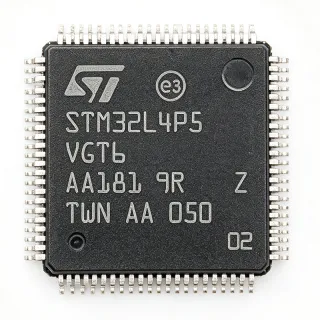
STM32F411VET6TR - 100MHz Cortex-M4 MCU 512KB Flash | STMicroelectronics
MPN: STM32F411VET6TR ✓ Hoạt độngSTM32F411VET6TR Tóm tắt
A microcontroller (MCU) is a single-chip computer that integrates a CPU core, program memory (Flash), working memory (SRAM), and a rich set of peripherals such as timers, ADCs, communication controllers, and GPIOs. The STM32F411 sits in the Cortex-M4 -> ARM Cortex-M family -> 32-bit RISC microcontroller hierarchy, designed for deterministic real-time control with hardware floating-point acceleration and DSP extensions, which makes it well suited to motor control, audio processing, and signal-chain conditioning where 8/16-bit MCUs lack the headroom.
Key features of the STM32F411VET6TR include 125 DMIPS / 273 CoreMark performance, an ART Accelerator with 8 KB instruction cache that delivers near-zero-wait-state execution from Flash, a USB 2.0 OTG Full-Speed controller with on-chip PHY, and an SDMMC interface. The analog subsystem integrates three 12-bit 2.4 MSPS ADCs, two 12-bit DACs, and a buffered reference. Communication peripherals cover up to three USART, two UART, three SPI, two I2C, one CAN 2.0B, plus an external memory bus for SRAM/NOR/NAND. The 100-LQFP package exposes 81 GPIO for flexible system integration.
Architecturally, the STM32F411 uses a multi-AHB bus matrix (DCODE, SYSTEM, DMA1, DMA2) with two seven-channel DMAs to keep peripheral and CPU traffic parallelized, and a Cortex-M4 core with single-precision FPU, MPU, and NVIC for hardware-prioritized interrupts. Power gating through the integrated PVD, low-power Run, Sleep, Stop, and Standby modes is coordinated by the RCC and PWR blocks to support battery-powered end products.
Typical applications include USB HID/CDC devices, sensor fusion nodes, audio front ends (USB microphone, USB headphone), digital power conversion, drones, gaming controllers, and human-machine interface (HMI) modules. The 100 MHz Cortex-M4 with hardware FPU also makes it a frequent choice for CNC pre-processors and industrial gateways requiring deterministic wired connectivity.
When designing with this device, route the VDD/VDDA pins through a star topology with separate 100 nF + 4.7 uF decoupling at each pin, and tie BOOT0 to ground via 10 kOhm for normal boot from Flash. The 100-LQFP requires thermal relief and proper copper pour for the 81 GPIO to keep switching noise out of the analog domain.
This page synthesizes distributor pricing, drop-in alternatives in the same 100-LQFP footprint, and practical design notes not found in the manufacturer datasheet.
Bộ thay thế dễ dàng lắp đặt cho STM32F411VET6TR — cùng gói, chân-to-chân tương thích. Các bộ phận yêu cầu hàn PCB bị loại trừ.
Các biến thể trong loạt này
Các mẫu cùng loạt có thể lắp đặt dễ dàng tương thích với STM32F411VET6TR (cùng hình factor và footprint) — khác nhau ở Package, Communication Interfaces, Operating Temperature, ADC, Core.
STM32F411VET6
✅ Drop-InLiên hệ để biết giá
Xem tài liệu →STM32F411RET6TR
✅ Drop-InLiên hệ để biết giá
Xem tài liệu →STM32F405VGT6TR
✅ Drop-InLiên hệ để biết giá
Xem tài liệu →STM32F407VET6TR
✅ Drop-In✓ Còn hàng
$3.4498 / Đơn vị
Xem tài liệu →GD32F303VET6
✅ Drop-In📋 Tham chiếu thay thế (không có trong danh mục)
STM32F411VET6TR Tỷ lệ tối đa & tính chất điện
| Core Architecture | ARM Cortex-M4 with FPU and DSP |
| Tần số xung maksimum | 100 MHz |
| Performance | 125 DMIPS / 273 CoreMark |
| Program Memory (Flash) | 512 KB |
| SRAM | 128 KB |
| Supply Voltage (VDD) | 1.7 V to 3.6 V |
| Nhiệt độ hoạt động | -40 C to +85 C (grade 6) |
| Hộp | 100-LQFP (14x14 mm) |
| GPIO Count | 81 |
| ADC | 3x 12-bit, 2.4 MSPS |
| DAC | 2x 12-bit |
| USB | USB 2.0 OTG Full-Speed with on-chip PHY |
| CAN | 1x CAN 2.0B |
| SDMMC | Yes |
| External Memory Bus | Yes (SRAM/NOR/NAND) |
| DMA | 2x 7-channel controllers |
| ART Accelerator | 8 KB instruction cache |
| Kiểu lắp đặt | Surface Mount |
| Trạng thái RoHS | Compliant |
Cấu hình chân STM32F411VET6TR
| Chân 1 | PE2 — GPIO PE2 / TRACECLK / FSMC_A23 |
| Chân 2 | PE3 — GPIO PE3 / TRACED0 / FSMC_A19 |
| Chân 3 | PE4 — GPIO PE4 / TRACED1 / FSMC_A20 |
| Chân 4 | PE5 — GPIO PE5 / TRACED2 / FSMC_A21 |
| Chân 5 | PE6 — GPIO PE6 / TRACED3 / FSMC_A22 |
| Chân 6 | VBAT — Backup battery supply input |
| Chân 7 | PC13 — GPIO PC13 / RTC_TAMP1 / WKUP2 |
| Chân 8 | PC14 — GPIO PC14 / OSC32_IN |
| Chân 9 | PC15 — GPIO PC15 / OSC32_OUT |
| Chân 10 | VSS — Ground |
| Chân 11 | VDD — Digital supply 1.7-3.6 V |
| Chân 12 | OSC_IN — HSE oscillator input |
| Chân 13 | OSC_OUT — HSE oscillator output |
| Chân 14 | NRST — Active-low reset input |
| Chân 15 | PC0 — GPIO PC0 / ADC1_IN10 |
| Chân 16 | PC1 — GPIO PC1 / ADC1_IN11 |
| Chân 17 | PC2 — GPIO PC2 / ADC1_IN12 |
| Chân 18 | PC3 — GPIO PC3 / ADC1_IN13 |
| Chân 19 | VSSA — Analog ground |
| Chân 20 | VDDA — Analog supply 1.7-3.6 V |
| Chân 21 | PA0 — GPIO PA0 / WKUP / ADC1_IN0 / TIM2_CH1 |
| Chân 22 | PA1 — GPIO PA1 / ADC1_IN1 / TIM2_CH2 |
| Chân 23 | PA2 — GPIO PA2 / USART2_TX / ADC1_IN2 / TIM2_CH3 |
| Chân 24 | PA3 — GPIO PA3 / USART2_RX / ADC1_IN3 / TIM2_CH4 |
| Chân 25 | VSS — Ground |
| Chân 26 | VDD — Digital supply 1.7-3.6 V |
| Chân 27 | PA4 — GPIO PA4 / SPI1_NSS / ADC1_IN4 / DAC1_OUT |
| Chân 28 | PA5 — GPIO PA5 / SPI1_SCK / ADC1_IN5 / DAC2_OUT |
| Chân 29 | PA6 — GPIO PA6 / SPI1_MISO / ADC1_IN6 / TIM3_CH1 |
| Chân 30 | PA7 — GPIO PA7 / SPI1_MOSI / ADC1_IN7 / TIM3_CH2 |
| Chân 31 | PC4 — GPIO PC4 / ADC1_IN14 |
| Chân 32 | PC5 — GPIO PC5 / ADC1_IN15 |
| Chân 33 | PB0 — GPIO PB0 / ADC1_IN8 / TIM3_CH3 |
| Chân 34 | PB1 — GPIO PB1 / ADC1_IN9 / TIM3_CH4 |
| Chân 35 | PB2 — GPIO PB2 / BOOT1 |
| Chân 36 | PE7 — GPIO PE7 / FSMC_D4 |
| Chân 37 | PE8 — GPIO PE8 / FSMC_D5 |
| Chân 38 | PE9 — GPIO PE9 / FSMC_D6 |
| Chân 39 | PE10 — GPIO PE10 / FSMC_D7 |
| Chân 40 | PE11 — GPIO PE11 / FSMC_D8 |
| Chân 41 | PE12 — GPIO PE12 / FSMC_D9 |
| Chân 42 | PE13 — GPIO PE13 / FSMC_D10 |
| Chân 43 | PE14 — GPIO PE14 / FSMC_D11 |
| Chân 44 | PE15 — GPIO PE15 / FSMC_D12 |
| Chân 45 | PB10 — GPIO PB10 / I2C2_SCL / USART3_TX |
| Chân 46 | PB11 — GPIO PB11 / I2C2_SDA / USART3_RX |
| Chân 47 | VCAP_1 — Core voltage decoupling (1.2 V LDO output) |
| Chân 48 | VDD — Digital supply 1.7-3.6 V |
| Chân 49 | PB12 — GPIO PB12 / SPI2_NSS / I2S2_WS |
| Chân 50 | PB13 — GPIO PB13 / SPI2_SCK / I2S2_CK |
| Chân 51 | PB14 — GPIO PB14 / SPI2_MISO / TIM12_CH1 |
| Chân 52 | PB15 — GPIO PB15 / SPI2_MOSI / TIM12_CH2 |
| Chân 53 | PD8 — GPIO PD8 / FSMC_D13 / USART3_TX |
| Chân 54 | PD9 — GPIO PD9 / FSMC_D14 / USART3_RX |
| Chân 55 | PD10 — GPIO PD10 / FSMC_D15 |
| Chân 56 | PD11 — GPIO PD11 / FSMC_A16 |
| Chân 57 | PD12 — GPIO PD12 / FSMC_A17 / TIM4_CH1 |
| Chân 58 | PD13 — GPIO PD13 / FSMC_A18 / TIM4_CH2 |
| Chân 59 | PD14 — GPIO PD14 / FSMC_D0 / TIM4_CH3 |
| Chân 60 | PD15 — GPIO PD15 / FSMC_D1 / TIM4_CH4 |
| Chân 61 | PC6 — GPIO PC6 / USART6_TX / TIM3_CH1 |
| Chân 62 | PC7 — GPIO PC7 / USART6_RX / TIM3_CH2 |
| Chân 63 | PC8 — GPIO PC8 / SDMMC_D0 / TIM3_CH3 |
| Chân 64 | PC9 — GPIO PC9 / SDMMC_D1 / TIM3_CH4 |
| Chân 65 | PA8 — GPIO PA8 / USART1_CK / TIM1_CH1 / MCO1 |
| Chân 66 | PA9 — GPIO PA9 / USART1_TX / TIM1_CH2 |
| Chân 67 | PA10 — GPIO PA10 / USART1_RX / TIM1_CH3 |
| Chân 68 | PA11 — GPIO PA11 / USB_DM / CAN1_RX |
| Chân 69 | PA12 — GPIO PA12 / USB_DP / CAN1_TX |
| Chân 70 | PA13 — GPIO PA13 / JTMS / SWDIO |
| Chân 71 | VCAP_2 — Core voltage decoupling (1.2 V LDO output) |
| Chân 72 | VDD — Digital supply 1.7-3.6 V |
| Chân 73 | PA14 — GPIO PA14 / JTCK / SWDCLK |
| Chân 74 | PA15 — GPIO PA15 / JTDI / SPI1_NSS / TIM2_CH1 |
| Chân 75 | PC10 — GPIO PC10 / SDMMC_D2 / USART3_TX |
| Chân 76 | PC11 — GPIO PC11 / SDMMC_D3 / USART3_RX |
| Chân 77 | PC12 — GPIO PC12 / SDMMC_CK / USART3_CK |
| Chân 78 | PD0 — GPIO PD0 / FSMC_D2 / CAN1_RX |
| Chân 79 | PD1 — GPIO PD1 / FSMC_D3 / CAN1_TX |
| Chân 80 | PD2 — GPIO PD2 / SDMMC_CMD / TIM3_ETR |
| Chân 81 | PD3 — GPIO PD3 / FSMC_CLK / USART2_CTS |
| Chân 82 | PD4 — GPIO PD4 / FSMC_NOE / USART2_RTS |
| Chân 83 | PD5 — GPIO PD5 / FSMC_NWE / USART2_TX |
| Chân 84 | PD6 — GPIO PD6 / FSMC_NWAIT / USART2_RX |
| Chân 85 | PD7 — GPIO PD7 / FSMC_NE1 / USART2_CK |
| Chân 86 | PB3 — GPIO PB3 / JTDO / TRACESWO / SPI1_SCK / TIM2_CH2 |
| Chân 87 | PB4 — GPIO PB4 / NJTRST / SPI1_MISO / TIM3_CH1 |
| Chân 88 | PB5 — GPIO PB5 / SPI1_MOSI / I2C1_SMBA / TIM3_CH2 |
| Chân 89 | PB6 — GPIO PB6 / I2C1_SCL / USART1_TX / TIM4_CH1 |
| Chân 90 | PB7 — GPIO PB7 / I2C1_SDA / USART1_RX / TIM4_CH2 |
| Chân 91 | BOOT0 — Boot mode select (0 = main Flash, 1 = system bootloader) |
| Chân 92 | PB8 — GPIO PB8 / I2C1_SCL / CAN1_RX / TIM4_CH3 |
| Chân 93 | PB9 — GPIO PB9 / I2C1_SDA / CAN1_TX / TIM4_CH4 |
| Chân 94 | PE0 — GPIO PE0 / TIM4_ETR |
| Chân 95 | PE1 — GPIO PE1 / FSMC_NBL0 |
| Chân 96 | VSS — Ground |
| Chân 97 | VSS — Ground |
| Chân 98 | PE2_ALT — Alias region for PE2 / FSMC_A23 (per datasheet) |
| Chân 99 | VREF+ — ADC/DAC positive reference voltage |
| Chân 100 | VREF- — ADC/DAC negative reference voltage |
Ứng dụng tiêu biểu
STM32F411VET6TR phù hợp cho 6 Áp dụngs: USB HID / CDC Device, Sensor Fusion / IMU Node, Audio Front End (USB Microphone / Headset), Industrial Gateway / HMI Controller, Drone Flight Controller Companion Board, Gaming Controller / HMI Bridge.
USB HID / CDC Device
The STM32F411VET6TR is a strong fit for USB Human Interface Devices and CDC virtual COM ports because of its integrated USB 2.0 OTG Full-Speed controller with on-chip PHY, removing the need for an external transceiver. The 100 MHz Cortex-M4 with hardware FPU handles USB stack processing, HID report packing, and CDC line coding within budget, while 512 KB Flash fits full USB class stacks (HID + CDC composite) plus a small RTOS. Use it for configuration tools, lab instruments, and custom peripherals where a 12 Mbps USB link and PC driverless enumeration are required. Power dissipation is modest at 100 MHz full load, so no external heatsinking is needed on the 100-LQFP.
Được đề xuất
Sensor Fusion / IMU Node
The STM32F411VET6TR suits 9-axis IMU sensor fusion nodes because its 100 MHz Cortex-M4 with FPU and DSP can run a real-time Madgwick or Mahony filter with 1 kHz update rates. The 3x 12-bit 2.4 MSPS ADCs sample analog sensor outputs while the SPI and I2C controllers drive the accelerometer, gyro, and magnetometer, and the DMA offloads conversion to memory without CPU intervention. The 128 KB SRAM accommodates FIFO buffers and the filter state, while 512 KB Flash holds the bootloader, RTOS, and sensor drivers. 1.7-3.6 V operation is friendly to Li-ion battery rails commonly used in wearables and drones.
Được đề xuất
Audio Front End (USB Microphone / Headset)
The STM32F411VET6TR is a common choice for USB audio peripherals because the USB OTG Full-Speed link can stream 48 kHz / 16-bit stereo audio over isochronous endpoints while the Cortex-M4 performs basic DSP, gain control, and sidetone. The 2x 12-bit DAC and I2S interface support headphone or line-out stages, and the SDMMC controller enables optional WAV file playback from a microSD card. With 128 KB SRAM the MCU can buffer several milliseconds of audio while leaving headroom for the USB stack, and 512 KB Flash holds a full USB audio class 1.0 implementation. Power is held low enough for bus-powered designs drawing 100 mA or less from USB.
Được đề xuất
Industrial Gateway / HMI Controller
The STM32F411VET6TR fits industrial gateway and HMI controller roles where deterministic RS-485, Modbus, or CAN 2.0B communication and a TFT display are required. The 100-LQFP exposes 81 GPIO, three USART, two UART, three SPI, two I2C, and a CAN 2.0B interface, supporting multi-drop industrial networks and parallel LCD/SDRAM through the external memory bus. The Cortex-M4 with FPU handles protocol stacks plus a small LVGL or emWin HMI, and 512 KB Flash comfortably stores bootloader, application, OTA staging, and fonts. -40 to +85 C operation and 3.6 V tolerant I/O are aligned with industrial cabinet environments.
Được đề xuất
Drone Flight Controller Companion Board
The STM32F411VET6TR works well as a companion processor or payload controller in drone systems, offloading navigation, camera control, or telemetry from the main flight controller. The 100 MHz Cortex-M4 with FPU executes CMSIS-DSP and CMSIS-NN inferences for on-board computer vision, while the SDMMC interface logs mission data to microSD. CAN and USART provide robust links to ESCs and the flight controller, and the 81 GPIO drive auxiliary actuators. Battery-friendly 1.7-3.6 V operation supports direct Li-Po input through a small LDO, and the small 100-LQFP footprint fits tight companion boards.
Được đề xuất
Gaming Controller / HMI Bridge
The STM32F411VET6TR can serve as the bridge MCU in wired and wireless gaming controllers, scanning button matrices, driving RGB LED chains, and presenting a USB HID or Bluetooth-HID endpoint. The 100 MHz Cortex-M4 with FPU runs USB-HID class driver plus anti-aliasing filtering on analog sticks, and the timers drive PWM for rumble motors with hardware dead-time insertion. 128 KB SRAM holds debounced input FIFOs and a USB report buffer, while 512 KB Flash carries bootloader, application, and device profiles. 1.7-3.6 V operation supports direct Li-ion battery power with simple boost regulation.
Được đề xuất
Tóm tắt các sản phẩm được đề xuất
Dữ liệu tham khảo kỹ thuật cho STM32F411VET6TR — so sánh, hướng dẫn thiết kế và thông tin tuân thủ.
Hướng dẫn chọn lựa
So sánh với các sản phẩm thay thế
| Tham số | Sản phẩm này | STM32F411VET6 | STM32F411RET6TR | STM32F405VGT6TR | STM32F407VET6TR | GD32F303VET6 |
|---|---|---|---|---|---|---|
| Brand | STMicroelectronics | STMicroelectronics | STMicroelectronics | STMicroelectronics | STMicroelectronics | GigaDevice |
| Package | 100-LQFP (14x14) | 100-LQFP (14x14) - same | 100-LQFP (14x14) - same | 100-LQFP (14x14) - same | 100-LQFP (14x14) - same | 100-LQFP (14x14) - same |
| Core | Cortex-M4F @ 100 MHz | Cortex-M4F @ 100 MHz | Cortex-M4F @ 100 MHz | Cortex-M4F @ 168 MHz | Cortex-M4F @ 168 MHz | Cortex-M4 (no FPU) @ 120 MHz |
| Flash | 512 KB | 512 KB | 256 KB | 1 MB | 512 KB | 512 KB |
| SRAM | 128 KB | 128 KB | 128 KB | 192 KB | 128 KB | 64 KB |
| USB | USB OTG FS, on-chip PHY | USB OTG FS, on-chip PHY | USB OTG FS, on-chip PHY | USB OTG FS + HS (ext PHY) | USB OTG FS + HS (ext PHY) | USB OTG FS |
| Ethernet MAC | No | No | No | Yes (MII/RMII) | Yes (MII/RMII) | No |
| FPU | Yes (single-precision) | Yes | Yes | Yes | Yes | No |
Bảo phân biệt quan trọng
- Higher performance than STM32F411RET6 with same 100-LQFP footprint (vsSTM32F411RET6TR)
- USB OTG Full-Speed with on-chip PHY, no external transceiver required (vsSTM32F405VGT6TR)
- GigaDevice cross-source option for cost reduction (vsGD32F303VET6)
Ghi chú thiết kế
Estimated: at 100 MHz full CPU load and 3.3 V VDD, the typical core current of an STM32F411 is around 12-15 mA. Add at least 100 nF + 4.7 uF ceramic on every VDD pin (48, 72, 11, 25, 26) plus 100 nF + 1 uF on VDDA pin 20, routed with star topology. Place a ferrite bead on the analog supply if the ADC is used at better than 10-bit effective resolution. Tie BOOT0 low through 10 kOhm to ground for normal Flash boot.
Estimated: at maximum 100 MHz and 3.6 V with all peripherals active, the package dissipation is well under 200 mW and the 100-LQFP with 1 oz 4-layer copper does not require a heatsink. Keep the exposed center pad in mind when migrating to a different STM32F4 with exposed pad (LQFP64/100 has no center pad; LQFP176/176BGA do). For industrial -40 to +85 C operation, derate clock speed above 70 C ambient if the application drives many GPIOs at high slew.
Do not leave NRST floating - it must have an external 10 kOhm pull-up and a 100 nF cap to ground for clean reset. The OSC_IN/OSC_OUT pins require a load-capacitor pair sized to the crystal (typically 5-20 pF). PC13 through PC15 on the 100-LQFP are shared with the RTC domain - do not use them as outputs if the RTC tamper or wake-up function is needed. BOOT0 must be sampled at NRST deassertion; if you reconfigure BOOT0 in firmware, it has no effect until the next reset.
Thông tin tuân thủ
Industrial grade-6 -40 to +85 C; not AEC-Q100 qualified - use STM32F4 automotive grades (e.g. STM32F412RG) for automotive designs