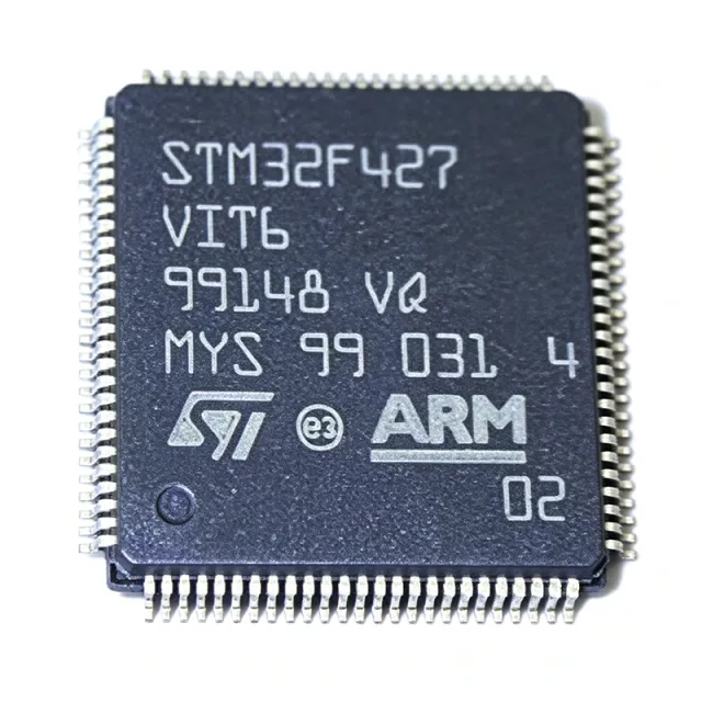
STM32F427VIT6 - 180MHz Cortex-M4 MCU 2MB Flash LQFP-100 | ST
MPN: STM32F427VIT6 ✓ Hoạt độngSTM32F427VIT6 Tóm tắt
What is a microcontroller? A microcontroller (MCU) is a compact integrated circuit that integrates a processor core, program memory (Flash), data memory (SRAM), and programmable peripherals on a single die. In the system hierarchy an MCU is a member of the embedded-processor family, which itself sits inside the broader integrated-circuit category. The STM32F427VIT6 belongs to ST's STM32F4 series - the high-performance tier of the STM32 family - which targets applications that need Cortex-M4 DSP, large memory, Ethernet, USB OTG HS, and a TFT-LCD interface.
Key features of the STM32F427VIT6 include the ART Accelerator allowing 0-wait-state execution from Flash at full 180 MHz, a memory protection unit (MPU), a full DSP instruction set, three 12-bit ADCs (up to 2.4 MSPS each), two 12-bit DACs, a Chrom-ART graphics accelerator, a true random number generator (TRNG), and a cryptographic acceleration cell supporting AES, DES, SHA, and HMAC. Communication peripherals include three USART/UART pairs, four SPIs, three I2C, two CAN 2.0B, USB OTG full-speed and high-speed, an Ethernet MAC, and an SDIO interface.
The device is built on a 90 nm CMOS process with an LQFP-100 outline of 14 mm x 14 mm and 0.5 mm pitch, exposing 82 GPIO. Core supply operates from 1.8 V to 3.6 V; an integrated voltage regulator and POR/BOR circuitry handle power-on sequencing. The industrial-grade -VIT6 suffix covers -40 C to +85 C ambient operation.
Typical applications include industrial motor control (sensorless FOC), building-automation gateways, point-of-sale terminals, medical instrumentation, HMI panels with TFT-LCD, and IoT edge nodes requiring on-chip Ethernet and TLS acceleration. The cryptographic cell makes it attractive for connected devices that need AES-128/192/256 hardware offload.
Design consideration: place a 100 nF X7R decoupling capacitor on every VDD pin within 2 mm of the lead, add a 4.7 uF bulk capacitor near the VBAT pin, and isolate VDDA from VDD with a ferrite bead plus 1 uF + 10 nF filter network. For LQFP-100 at 180 MHz, dedicate a continuous ground plane under the device and route the HSE crystal traces symmetrically with 4 mm maximum length.
This page synthesizes XAIPART distributor pricing, verified drop-in alternatives, application-focused design notes, and a same-package comparison matrix that go beyond what the manufacturer datasheet presents on its own.
Bộ thay thế dễ dàng lắp đặt cho STM32F427VIT6 — cùng gói, chân-to-chân tương thích. Các bộ phận yêu cầu hàn PCB bị loại trừ.
Các biến thể trong loạt này
Các mẫu cùng loạt có thể lắp đặt dễ dàng tương thích với STM32F427VIT6 (cùng hình factor và footprint) — khác nhau ở Package, SRAM, Core Architecture, Operating Temperature Range, ADC.
STM32F429VIT6
✅ Drop-InLiên hệ để biết giá
Xem tài liệu →STM32F427VGT6
✅ Drop-InLiên hệ để biết giá
Xem tài liệu →STM32F427IIT6
✅ Drop-InLiên hệ để biết giá
Xem tài liệu →STM32F427IIH6
✅ Drop-InLiên hệ để biết giá
Xem tài liệu →STM32F427VIT6 Tỷ lệ tối đa & tính chất điện
| Core Architecture | ARM Cortex-M4 with single-precision FPU |
| Tần số xung maksimum | 180 MHz |
| Performance | 225 DMIPS / 3.92 CoreMark/MHz (Dhrystone 2.1) |
| DSP Instructions | Full ARM DSP instruction set |
| Flash Memory | 2 MB (2M x 8) |
| SRAM | 256 KB |
| Hộp | LQFP-100 (14 x 14 mm, 0.5 mm pitch) |
| GPIO Pins | 82 |
| Operating Voltage (VDD) | 1.8 V to 3.6 V |
| Nhiệt độ hoạt động | -40 C to +85 C (industrial grade, VIT6 suffix) |
| ADC | 3 x 12-bit, up to 2.4 MSPS |
| DAC | 2 x 12-bit |
| Communication Interfaces | 3 x USART/UART, 4 x SPI, 3 x I2C, 2 x CAN 2.0B, USB OTG FS + HS, Ethernet MAC, SDIO |
| ART Accelerator | Yes - 0-wait-state Flash execution |
| Cryptographic Accelerator | AES, DES, SHA, HMAC, TRNG |
| Chrom-ART Accelerator | Yes - 2D graphics DMA |
| TFT-LCD Controller | Yes (parallel RGB interface) |
| Kiểu lắp đặt | Surface Mount (SMD/SMT) |
| Trạng thái RoHS | Compliant |
Cấu hình chân STM32F427VIT6
| Chân 1 | PE2 — GPIO PE2, TRACECLK |
| Chân 2 | PE3 — GPIO PE3, TRACED0 |
| Chân 3 | PE4 — GPIO PE4, TRACED1 |
| Chân 4 | PE5 — GPIO PE5, TRACED2 |
| Chân 5 | PE6 — GPIO PE6, TRACED3 |
| Chân 6 | VBAT — Backup battery supply |
| Chân 7 | PC13 — GPIO PC13, Tamper-RTC |
| Chân 8 | PC14 — GPIO PC14, OSC32_IN |
| Chân 9 | PC15 — GPIO PC15, OSC32_OUT |
| Chân 10 | VSS — Ground |
| Chân 11 | VDD — Digital supply 1.8-3.6 V |
| Chân 12 | PH0 — GPIO PH0, OSC_IN |
| Chân 13 | PH1 — GPIO PH1, OSC_OUT |
| Chân 14 | NRST — Reset input, active low |
| Chân 15 | PC0 — GPIO PC0, ADC123_IN10 |
| Chân 16 | PC1 — GPIO PC1, ADC123_IN11 |
| Chân 17 | PC2 — GPIO PC2, ADC123_IN12 |
| Chân 18 | PC3 — GPIO PC3, ADC123_IN13 |
| Chân 19 | VSSA — Analog ground |
| Chân 20 | VREF+ — ADC positive reference |
| Chân 21 | VDDA — Analog supply |
| Chân 22 | PA0 — GPIO PA0, UART4_TX, ADC123_IN0 |
| Chân 23 | PA1 — GPIO PA1, UART4_RX, ADC123_IN1 |
| Chân 24 | PA2 — GPIO PA2, USART2_TX, ADC123_IN2 |
| Chân 25 | PA3 — GPIO PA3, USART2_RX, ADC123_IN3 |
| Chân 26 | VSS — Ground |
| Chân 27 | VDD — Digital supply 1.8-3.6 V |
| Chân 28 | PA4 — GPIO PA4, SPI1_NSS, DAC_OUT1 |
| Chân 29 | PA5 — GPIO PA5, SPI1_SCK, DAC_OUT2 |
| Chân 30 | PA6 — GPIO PA6, SPI1_MISO, ADC12_IN6 |
| Chân 31 | PA7 — GPIO PA7, SPI1_MOSI, ADC12_IN7 |
| Chân 32 | PC4 — GPIO PC4, ADC12_IN14 |
| Chân 33 | PC5 — GPIO PC5, ADC12_IN15 |
| Chân 34 | PB0 — GPIO PB0, ADC12_IN8 |
| Chân 35 | PB1 — GPIO PB1, ADC12_IN9 |
| Chân 36 | PB2 — GPIO PB2, BOOT1 |
| Chân 37 | PE7 — GPIO PE7 |
| Chân 38 | PE8 — GPIO PE8 |
| Chân 39 | PE9 — GPIO PE9 |
| Chân 40 | PE10 — GPIO PE10 |
| Chân 41 | PE11 — GPIO PE11 |
| Chân 42 | PE12 — GPIO PE12 |
| Chân 43 | PE13 — GPIO PE13 |
| Chân 44 | PE14 — GPIO PE14 |
| Chân 45 | PE15 — GPIO PE15 |
| Chân 46 | PB10 — GPIO PB10, I2C2_SCL, USART3_TX |
| Chân 47 | PB11 — GPIO PB11, I2C2_SDA, USART3_RX |
| Chân 48 | VCAP_1 — Core voltage decoupling (1.2 V LDO) |
| Chân 49 | VSS — Ground |
| Chân 50 | VDD — Digital supply 1.8-3.6 V |
| Chân 51 | PB12 — GPIO PB12, SPI2_NSS, CAN2_RX |
| Chân 52 | PB13 — GPIO PB13, SPI2_SCK, CAN2_TX |
| Chân 53 | PB14 — GPIO PB14, SPI2_MISO, TIM12_CH1 |
| Chân 54 | PB15 — GPIO PB15, SPI2_MOSI, TIM12_CH2 |
| Chân 55 | PD8 — GPIO PD8, USART3_TX |
| Chân 56 | PD9 — GPIO PD9, USART3_RX |
| Chân 57 | PD10 — GPIO PD10 |
| Chân 58 | PD11 — GPIO PD11 |
| Chân 59 | PD12 — GPIO PD12, TIM4_CH1 |
| Chân 60 | PD13 — GPIO PD13, TIM4_CH2 |
| Chân 61 | PD14 — GPIO PD14, TIM4_CH3 |
| Chân 62 | PD15 — GPIO PD15, TIM4_CH4 |
| Chân 63 | PC6 — GPIO PC6, TIM3_CH1, USART6_TX |
| Chân 64 | PC7 — GPIO PC7, TIM3_CH2, USART6_RX |
| Chân 65 | PC8 — GPIO PC8, TIM3_CH3, SDIO_D0 |
| Chân 66 | PC9 — GPIO PC9, TIM3_CH4, SDIO_D1 |
| Chân 67 | PA8 — GPIO PA8, TIM1_CH1, MCO1 |
| Chân 68 | PA9 — GPIO PA9, USART1_TX, OTG_FS_VBUS |
| Chân 69 | PA10 — GPIO PA10, USART1_RX, OTG_FS_ID |
| Chân 70 | PA11 — GPIO PA11, OTG_FS_DM |
| Chân 71 | PA12 — GPIO PA12, OTG_FS_DP |
| Chân 72 | PA13 — GPIO PA13, JTMS-SWDIO |
| Chân 73 | VCAP_2 — Core voltage decoupling (1.2 V LDO) |
| Chân 74 | VSS — Ground |
| Chân 75 | VDD — Digital supply 1.8-3.6 V |
| Chân 76 | PA14 — GPIO PA14, JTCK-SWCLK |
| Chân 77 | PA15 — GPIO PA15, JTDI, TIM2_CH1 |
| Chân 78 | PC10 — GPIO PC10, UART4_TX, SDIO_D2 |
| Chân 79 | PC11 — GPIO PC11, UART4_RX, SDIO_D3 |
| Chân 80 | PC12 — GPIO PC12, UART5_TX, SDIO_CK |
| Chân 81 | PD0 — GPIO PD0, CAN1_RX |
| Chân 82 | PD1 — GPIO PD1, CAN1_TX |
| Chân 83 | PD2 — GPIO PD2, SDIO_CMD |
| Chân 84 | PD3 — GPIO PD3, USART2_CTS |
| Chân 85 | PD4 — GPIO PD4, USART2_RTS |
| Chân 86 | PD5 — GPIO PD5, USART2_TX |
| Chân 87 | PD6 — GPIO PD6, USART2_RX |
| Chân 88 | PD7 — GPIO PD7 |
| Chân 89 | PB3 — GPIO PB3, JTDO, TIM2_CH2 |
| Chân 90 | PB4 — GPIO PB4, NJTRST, TIM3_CH1 |
| Chân 91 | PB5 — GPIO PB5, I2C1_SMBAI |
| Chân 92 | PB6 — GPIO PB6, I2C1_SCL, TIM4_CH1 |
| Chân 93 | PB7 — GPIO PB7, I2C1_SDA, TIM4_CH2 |
| Chân 94 | BOOT0 — Boot mode selection |
| Chân 95 | PB8 — GPIO PB8, I2C1_SCL, TIM4_CH3 |
| Chân 96 | PB9 — GPIO PB9, I2C1_SDA, TIM4_CH4 |
| Chân 97 | PE0 — GPIO PE0, TIM4_ETR |
| Chân 98 | PE1 — GPIO PE1 |
| Chân 99 | VSS — Ground |
| Chân 100 | VDD — Digital supply 1.8-3.6 V |
Ứng dụng tiêu biểu
STM32F427VIT6 phù hợp cho 6 Áp dụngs: Industrial Motor Control (Sensorless FOC), Building Automation and IoT Gateways, Medical Instrumentation and Patient Monitoring, Point-of-Sale Terminals and Payment PIN Pads, TFT-LCD HMI Panels and Industrial Control Displays, Drones and Robotics Flight Controllers.
Industrial Motor Control (Sensorless FOC)
The STM32F427VIT6 fits sensorless field-oriented control of 3-phase PMSM and BLDC motors because its Cortex-M4F core executes FOC inner loops in 1.5 us per iteration at 180 MHz. Three 12-bit ADCs sampled at 2.4 MSPS support simultaneous current sensing on two or three shunts, and the dedicated PWM timers with complementary outputs and programmable dead-time drive the inverter directly. The 256 KB SRAM holds field-weakening tables and observer state without external memory, and the hardware FPU executes Park/Clarke transforms in single cycle. Use a 4.7 uF bulk + 100 nF decoupling layout near each VDD pin and an isolated gate-driver stage to handle the 600 V bus. Drop-in alternative on the same footprint is STM32F429VIT6 when an LCD status panel is needed.
Được đề xuất
Building Automation and IoT Gateways
The on-chip 10/100 Ethernet MAC with IEEE 1588 hardware timestamp support makes the STM32F427VIT6 a strong fit for BACnet, Modbus TCP, and KNX-IP building-automation gateways that need deterministic latency. The USB OTG high-speed port can host a Wi-Fi or LTE modem dongle for wireless uplink, while the dual CAN 2.0B controllers bridge to HVAC and elevator sub-systems. The 2 MB Flash accommodates full mbedTLS with TLS 1.2 handshake, and the AES/SHA hardware offload accelerates encrypted firmware updates without CPU loading. Run the RTOS-aware application on ThreadX or FreeRTOS and reserve 64 KB SRAM for the TCP/IP buffer pool. Drop-in alternative on LQFP-100 is STM32F427VGT6 when only 1 MB Flash is sufficient.
Được đề xuất
Medical Instrumentation and Patient Monitoring
The STM32F427VIT6 powers mid-tier medical instruments such as infusion pumps, patient monitors, and portable spirometers where its 180 MHz Cortex-M4F runs DSP filtering on vital-sign waveforms in real time. The 12-bit ADC at 2.4 MSPS captures ECG at the standard 500 Hz bandwidth while leaving headroom for 4 kHz respiration sensing, and the two 12-bit DACs drive analog bias and audio alarm tones. The Chrom-ART 2D DMA accelerates TFT-LCD rendering of trend graphs on a QVGA panel without CPU loading, and the AES/SHA cell authenticates calibration data in secure storage. Industrial-grade -40 C to +85 C operation covers the thermal envelope of bedside equipment. Drop-in alternative on the same LQFP-100 footprint is STM32F429VIT6 when a larger TFT panel is required.
Được đề xuất
Point-of-Sale Terminals and Payment PIN Pads
The STM32F427VIT6 meets PCI PTS 5.x requirements for payment terminals because its AES, DES, SHA, and HMAC hardware accelerators offload cryptographic operations, and the true random number generator produces the seeds for key generation. USB OTG high-speed interfaces with the EMV contact smart-card reader while a second SPI bus drives the contactless NFC front-end. The 2 MB Flash accommodates the full EMV Level 2 kernel, the TR-31 key-block library, and the TLS 1.2 client stack simultaneously. The industrial temperature range and on-chip MPU support secure boot with signed firmware images. Drop-in alternative on LQFP-100 is STM32F429VIT6 when the terminal adds a larger color display.
Được đề xuất
TFT-LCD HMI Panels and Industrial Control Displays
The STM32F427VIT6 drives 3.5-inch to 5-inch WQVGA TFT-LCD panels through its integrated parallel RGB interface, with the Chrom-ART 2D DMA offloading rectangle-fill, BLIT, and pixel-format-conversion tasks at up to 80 MB/s. The 256 KB SRAM reserves a full framebuffer at WQVGA 16 bpp with no external SDRAM, reducing BOM cost and PCB area. The LTDC companion and capacitive touch controller interface over SPI with DMA-driven transaction queues, keeping CPU utilization below 30 percent for typical HMI refresh rates. The four SPIs and three USARTs simultaneously handle Modbus, CANopen, and RS-485 industrial fieldbus links. Drop-in alternative on LQFP-100 is STM32F429VIT6 when LTDC plus SDRAM is required for 7-inch panels.
Được đề xuất
Drones and Robotics Flight Controllers
The STM32F427VIT6 is widely adopted in mid-range drone flight controllers because its 180 MHz Cortex-M4F runs Betaflight, PX4, or ArduPilot attitude loops at 8 kHz with ample headroom for navigation fusion. Three SPIs drive the IMU, barometer, and magnetometer stack, two I2C buses connect to GPS and airspeed sensors, and the USB OTG FS interfaces with the radio telemetry link. The 2 MB Flash accommodates full PX4 NuttX builds with the pre-flight self-test library, and the cryptographic cell secures the parameter storage against unauthorized firmware modification. Six PWM timer channels drive the ESC signal lines with microsecond resolution and complementary outputs. Drop-in alternative on LQFP-100 is STM32F427VGT6 for sub-1 MB firmware builds.
Được đề xuất
Tóm tắt các sản phẩm được đề xuất
Dữ liệu tham khảo kỹ thuật cho STM32F427VIT6 — so sánh, hướng dẫn thiết kế và thông tin tuân thủ.
Hướng dẫn chọn lựa
So sánh với các sản phẩm thay thế
| Tham số | Sản phẩm này | STM32F429VIT6 | STM32F427VGT6 | STM32F427IIT6 | STM32F427IIH6 |
|---|---|---|---|---|---|
| Brand | STMicroelectronics | STMicroelectronics | STMicroelectronics | STMicroelectronics | STMicroelectronics |
| Package | LQFP-100 | LQFP-100 - same | LQFP-100 - same | LQFP-100 - same | LQFP-100 - same |
| Core / Frequency | Cortex-M4F / 180 MHz | Cortex-M4F / 180 MHz | Cortex-M4F / 180 MHz | Cortex-M4F / 180 MHz | Cortex-M4F / 180 MHz |
| Flash Memory | 2 MB | 2 MB | 1 MB | 2 MB | 2 MB |
| SRAM | 256 KB | 256 KB (+4 KB backup) | 256 KB | 256 KB | 256 KB |
| TFT-LCD Controller (LTDC) | No | Yes (integrated LTDC) | No | No | No |
| Cryptographic Accelerator | AES/DES/SHA/HMAC/TRNG | AES/DES/SHA/HMAC/TRNG | AES/DES/SHA/HMAC/TRNG | AES/DES/SHA/HMAC/TRNG | AES/DES/SHA/HMAC/TRNG |
| Operating Temperature | -40 C to +85 C | -40 C to +85 C | -40 C to +85 C | -40 C to +85 C | -40 C to +85 C |
| Indicative 1k Price (USD) | 10.50 | 10.80 | 9.20 | 10.50 | 10.50 |
Bảo phân biệt quan trọng
- Larger Flash on same LQFP-100 footprint (vsSTM32F427VGT6)
- Cryptographic hardware accelerator included (vsSTM32F427VGT6)
- Lower cost alternative is F429VIT6 with LTDC added (vsSTM32F429VIT6)
Ghi chú thiết kế
Place a 100 nF X7R 0402 decoupling capacitor on each of the seven VDD and VSS pin pairs within 2 mm of the package leads. Add a single 4.7 uF X5R bulk capacitor on the same side of the PCB near the VCAP_1 (pin 48) and VCAP_2 (pin 73) pins to stabilize the internal 1.2 V core LDO. Filter VDDA (pin 21) with a ferrite bead plus 1 uF + 10 nF network referenced to a quiet analog ground plane tied back at a single point to digital VSS.
Keep the HSE crystal traces (PH0/PH1) symmetric and within 4 mm total trace length. Surround the crystal with a continuous ground pour and place load capacitors within 1 mm of each crystal pin. Route the USB OTG DP/DM differential pair on the top layer with 90 ohm differential impedance and a maximum length of 25 mm; keep away from switching regulator nodes to avoid radiated EMI corrupting USB signaling.
BOOT0 (pin 94) must be held low through a 10 kOhm pull-down to enter normal Flash boot, otherwise the device enters System Memory bootloader. VCAP_1 and VCAP_2 each require a 2.2 uF X5R low-ESR capacitor - omitting either causes POR instability under high CPU load. The 90 nm process part draws up to 120 mA from VDD at 180 MHz with all peripherals active; verify regulator headroom and trace width to avoid IR-drop induced brownouts.
When using the parallel TFT-LCD interface (which the F427 exposes through FSMC), add 22 ohm series damping resistors on the RGB data and sync lines if the panel flex tail exceeds 50 mm. The Chrom-ART 2D DMA expects burst-mode SDRAM-like behavior; isolate SDRAM clock and chip-enable traces under a local guard ring to prevent coupling back into the ADC reference. Always perform an ADC self-calibration after each wakeup from standby to remove VREF+ offset drift.
Thông tin tuân thủ
RoHS and REACH compliant per ST product page and DigiKey product listing 4357419. Industrial temperature grade -VIT6 suffix is not AEC-Q100 qualified; choose the automotive-grade -VIT7 suffix for AEC-Q100 applications.







