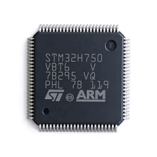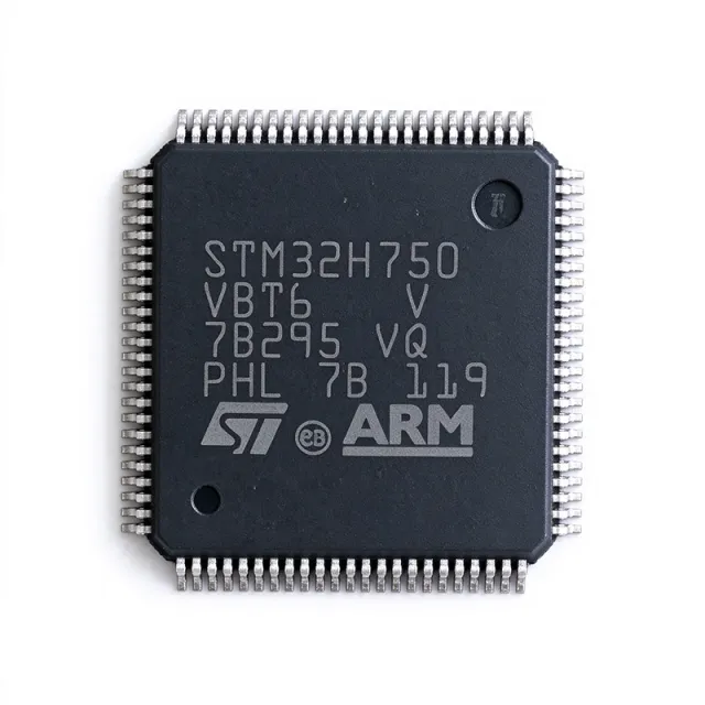
STM32H750VBT6 - 480MHz Cortex-M7 MCU, 128KB Flash | STMicroelectronics
MPN: STM32H750VBT6 ✓ Hoạt độngSTM32H750VBT6 Tóm tắt
A microcontroller (MCU) is a compact integrated circuit that combines a processor core, memory, and programmable I/O peripherals on a single die to govern a specific embedded operation. The STM32H750VBT6 sits at the top of the STM32H7 Value-Line hierarchy, which itself belongs to the broader STMicroelectronics STM32 family of 32-bit Arm Cortex-M microcontrollers, placing it well above mainstream families such as the STM32F4 in both clock speed and peripheral richness.
Key features include the 480 MHz Cortex-M7 core with DP-FPU and L1 cache, 1 MB of SRAM paired with only 128 KB of internal flash (a deliberate value-line trade-off that encourages executing code from external memory or XSPI RAM), a hardware cryptographic accelerator for AES/DES/3DES/HASH/SHA, and a rich connectivity set with 46 communication interfaces including USART, SPI, I2C, FDCAN, USB OTG, Ethernet MAC, an SDMMC, a TFT-LCD controller, a DCMI camera interface, and the Chrom-ART graphics accelerator. The device operates from a 1.62 V to 3.6 V supply across -40 C to +85 C.
Architecturally, the device integrates an MPU, an NVIC with hardware tail chaining, and four flexible power modes (Run, Sleep, Stop, Standby) managed through an internal SMPS-capable voltage regulator that can be configured to balance performance versus consumption. The Cortex-M7 superscalar pipeline with branch prediction delivers 2.14 DMIPS/MHz and a CoreMark score in the hundreds per MHz.
Typical applications include industrial motor drives and power conversion, medical instrumentation, smart-home and audio hubs, and HMI/graphics systems where 480 MHz throughput, 1 MB on-chip RAM, and LCD/camera interfaces remove the need for external memory in many designs.
Design consideration: with only 128 KB of internal flash, large applications must run from XSPI external memory or internal RAM, so budget code placement and boot configuration early in the project lifecycle.
This page synthesizes distributor pricing, drop-in alternatives, and practical design notes not found in the manufacturer datasheet alone.
Bộ thay thế dễ dàng lắp đặt cho STM32H750VBT6 — cùng gói, chân-to-chân tương thích. Các bộ phận yêu cầu hàn PCB bị loại trừ.
Các biến thể trong loạt này
Các mẫu cùng loạt có thể lắp đặt dễ dàng tương thích với STM32H750VBT6 (cùng hình factor và footprint) — khác nhau ở Communication Interfaces, Timers, SRAM, Package, Flash Memory.
STM32H743VIT6
Liên hệ để biết giá
Xem tài liệu →STM32H733VGT6
Liên hệ để biết giá
Xem tài liệu →STM32H735RGT6
Liên hệ để biết giá
Xem tài liệu →STM32H742VIT6
Liên hệ để biết giá
Xem tài liệu →STM32F756BGT6
Liên hệ để biết giá
Xem tài liệu →STM32H750VBT6TR
Liên hệ để biết giá
Xem tài liệu →STM32H753VIT6
📋 Tham chiếu thay thế (không có trong danh mục)
STM32F746VGT6
Liên hệ để biết giá
Xem tài liệu →STM32H750VBT6 Tỷ lệ tối đa & tính chất điện
| Core Architecture | Arm Cortex-M7 with double-precision FPU |
| Tần số xung maksimum | 480 MHz |
| Program Flash Memory | 128 KB |
| SRAM | 1 MB (256 KB DTCM + 256 KB AXI SRAM + 64 KB ITCM + 4 KB backup SRAM) |
| Supply Voltage (VDD) | 1.62 V to 3.6 V |
| Nhiệt độ hoạt động | -40 C to +85 C (grade 6) |
| Hộp | LQFP-100 (14x14 mm, 0.5 mm pitch) |
| Communication Interfaces | 46 (USART/UART, SPI, I2C, FDCAN, USB OTG FS+HS, Ethernet MAC, SDMMC, SAI) |
| Display Controller | TFT-LCD controller (LTDC) |
| Camera Interface | DCMI 8/14-bit parallel |
| Cryptographic Accelerator | AES/DES/3DES/HASH/SHA, true RNG |
| Graphics Accelerator | Chrom-ART (DMA2D) |
| Kiểu lắp đặt | Surface Mount |
| Cấp MSL | 3 |
| Trạng thái RoHS | Compliant (ROHS3) |
Cấu hình chân STM32H750VBT6
| Chân 1 | PE2 — GPIO PE2 / TRACECLK / SPI4_SCK / SAI1_MCLK_A / TIM9_CH1 / ETH_MII_TXD3 / DCMI_D3 |
| Chân 2 | PE3 — GPIO PE3 / TRACED0 / SAI1_SD_B / TIM15_CH2 / USART1_RX |
| Chân 3 | PE4 — GPIO PE4 / TRACED1 / SPI4_NSS / SAI1_FS_A / TIM15_CH1N / DCMI_D4 |
| Chân 4 | PE5 — GPIO PE5 / TRACED2 / TIM9_CH1 / SPI4_MISO / SAI1_SCK_A / DCMI_D5 |
| Chân 5 | PE6 — GPIO PE6 / TRACED3 / TIM1_BKIN2 / SPI4_MOSI / SAI1_SD_A / TIM15_CH2 / DCMI_D6 |
| Chân 6 | VBAT — Backup battery supply input |
| Chân 7 | PC13 — GPIO PC13 / RTC_TS1 / WKUP3 (tamper pin) |
| Chân 8 | PC14 — GPIO PC14 / OSC32_IN (LSE crystal) |
| Chân 9 | PC15 — GPIO PC15 / OSC32_OUT (LSE crystal) |
| Chân 10 | VSS — Ground |
| Chân 11 | VDD — Digital supply 1.62-3.6 V |
| Chân 12 | PH0 — GPIO PH0 / OSC_IN (HSE crystal) |
| Chân 13 | PH1 — GPIO PH1 / OSC_OUT (HSE crystal) |
| Chân 14 | NRST — Active-low reset input |
| Chân 15 | PC0 — GPIO PC0 / ADC1_INP10 / SAI1_FS_B / OTG_HS_ULPI_STP / DFSDM1_CKIN0 |
| Chân 16 | PC1 — GPIO PC1 / ADC1_INP11 / SAI1_MCLK_B / SDMMC2_CD / ETH_MDC / DFSDM1_DATIN1 |
| Chân 17 | PC2 — GPIO PC2 / ADC1_INP12 / SPI2_MISO / OTG_HS_ULPI_DIR / ETH_MII_TXD2 / DFSDM1_CKIN1 |
| Chân 18 | PC3 — GPIO PC3 / ADC1_INP13 / SPI2_MOSI / OTG_HS_ULPI_NXT / ETH_MII_TX_CLK / DFSDM1_DATIN2 |
| Chân 19 | VSSA — Analog ground |
| Chân 20 | VDDA — Analog supply 1.62-3.6 V |
| Chân 21 | PA0 — GPIO PA0 / ADC1_INP0 / TIM2_CH1 / TIM5_CH1 / USART2_CTS / UART4_TX / SAI1_SD_B / ETH_MII_CRS |
| Chân 22 | PA1 — GPIO PA1 / ADC1_INP1 / TIM2_CH2 / TIM5_CH2 / USART2_RTS / UART4_RX / SAI1_MCLK_B / ETH_MII_RX_CLK |
| Chân 23 | PA2 — GPIO PA2 / ADC1_INP2 / TIM2_CH3 / TIM5_CH3 / USART2_TX / SAI1_SCK_B / ETH_MDIO |
| Chân 24 | PA3 — GPIO PA3 / ADC1_INP3 / TIM2_CH4 / TIM5_CH4 / USART2_RX / OTG_HS_ULPI_D0 / ETH_MII_COL |
| Chân 25 | VSS — Ground |
| Chân 26 | VDD — Digital supply 1.62-3.6 V |
| Chân 27 | PA4 — GPIO PA4 / ADC1_INP4 / DAC1_OUT1 / SPI1_NSS / SPI3_NSS / USART2_CK / OTG_HS_SOF / DCMI_HSYNC |
| Chân 28 | PA5 — GPIO PA5 / ADC1_INP5 / DAC1_OUT2 / TIM2_CH1 / TIM8_CH1N / SPI1_SCK / OTG_HS_ULPI_CK |
| Chân 29 | PA6 — GPIO PA6 / ADC1_INP6 / TIM2_CH1 / TIM8_CH1 / SPI1_MISO / TIM13_CH1 / DCMI_PIXCLK |
| Chân 30 | PA7 — GPIO PA7 / ADC1_INP7 / TIM2_CH2 / TIM8_CH2 / SPI1_MOSI / TIM14_CH1 / ETH_MII_RX_DV / RMII_CRS_DV |
| Chân 31 | PC4 — GPIO PC4 / ADC2_INP4 / I2S1_MCK / SPDIFRX_IN0 / OTG_HS_ULPI_STP / ETH_MII_RXD0 / RMII_RXD0 |
| Chân 32 | PC5 — GPIO PC5 / ADC2_INP5 / SAI1_SD_A / SPDIFRX_IN1 / OTG_HS_ULPI_CK / ETH_MII_RXD1 / RMII_RXD1 |
| Chân 33 | PB0 — GPIO PB0 / ADC1_INP8 / TIM1_CH2N / TIM8_CH2N / OTG_HS_ULPI_D1 / ETH_MII_RXD2 / DFSDM1_CKOUT |
| Chân 34 | PB1 — GPIO PB1 / ADC1_INP9 / TIM1_CH3N / TIM8_CH3N / OTG_HS_ULPI_D2 / ETH_MII_RXD3 / DFSDM1_DATIN3 |
| Chân 35 | PB2 — GPIO PB2 / I2S1_SD / SPI3_MOSI / SAI1_SD_A / TIM15_CH1N / OTG_HS_ULPI_D4 / ETH_MII_TXD1 |
| Chân 36 | PF0 — GPIO PF0 / I2C2_SDA / I2S1_WS / OTG_HS_ULPI_D5 / TIM23_CH1 / DFSDM1_CKIN0 |
| Chân 37 | PF1 — GPIO PF1 / I2C2_SCL / I2S1_CK / OTG_HS_ULPI_D6 / TIM23_CH2 / DFSDM1_CKIN1 |
| Chân 38 | PF2 — GPIO PF2 / I2C2_SMBA / SAI1_SD_B / USART3_RTS / OTG_HS_ULPI_D7 / TIM23_CH3 / DFSDM1_CKIN2 |
| Chân 39 | PF3 — GPIO PF3 / ADC3_INP5 / SAI1_MCLK_B / USART3_CTS / OTG_HS_ULPI_NXT / TIM23_CH4 / DFSDM1_CKIN3 |
| Chân 40 | PF4 — GPIO PF4 / ADC3_INP6 / SAI1_SCK_B / TRACED0 / USART3_TX / DFSDM1_CKOUT |
| Chân 41 | PF5 — GPIO PF5 / ADC3_INP7 / SAI1_FS_B / TRACED1 / USART3_RX / DFSDM1_DATIN0 |
| Chân 42 | VSS — Ground |
| Chân 43 | VDD — Digital supply 1.62-3.6 V |
| Chân 44 | PF6 — GPIO PF6 / ADC3_INP8 / SAI1_SD_A / TIM16_CH1 / SPI5_NSS / SAI1_DFSDM1_DATIN1 |
| Chân 45 | PF7 — GPIO PF7 / ADC3_INP9 / SAI1_MCLK_A / TIM17_CH1 / SPI5_SCK / DFSDM1_DATIN2 |
| Chân 46 | PF8 — GPIO PF8 / ADC3_INP10 / SAI1_SCK_A / TIM13_CH1 / SPI5_MISO / DFSDM1_CKIN3 |
| Chân 47 | PF9 — GPIO PF9 / ADC3_INP11 / SAI1_FS_A / TIM14_CH1 / SPI5_MOSI / DFSDM1_DATIN3 |
| Chân 48 | PF10 — GPIO PF10 / ADC3_INP12 / SAI1_SD_B / TIM16_CH1N / SAI1_DFSDM1_CKOUT |
| Chân 49 | PH2 — GPIO PH2 / I2C2_SCL / SPI5_SD / OTG_HS_ULPI_STP / ETH_MII_CRS |
| Chân 50 | PH3 — GPIO PH3 / I2C2_SDA / SPI5_CK / OTG_HS_ULPI_DIR / ETH_MII_COL |
| Chân 51 | PH4 — GPIO PH4 / I2C1_SCL / SPI5_WS / OTG_HS_ULPI_NXT |
| Chân 52 | PH5 — GPIO PH5 / I2C1_SDA / SPI5_NSS / OTG_HS_ULPI_CK |
| Chân 53 | VSS — Ground |
| Chân 54 | VDD — Digital supply 1.62-3.6 V |
| Chân 55 | PA8 — GPIO PA8 / TIM1_CH1 / TIM8_CH1 / USART1_CK / OTG_FS_SOF / TIM14_CH1 / SAI1_SD_A_M6 |
| Chân 56 | PA9 — GPIO PA9 / TIM1_CH2 / USART1_TX / SPI2_SCK / SAI1_FS_A / OTG_FS_VBUS |
| Chân 57 | PA10 — GPIO PA10 / TIM1_CH3 / USART1_RX / SPI2_MISO / OTG_FS_ID / SAI1_SD_A_M5 |
| Chân 58 | PA11 — GPIO PA11 / TIM1_CH4 / USART1_CTS / CAN1_RX / OTG_FS_DM |
| Chân 59 | PA12 — GPIO PA12 / TIM1_ETR / USART1_RTS / CAN1_TX / OTG_FS_DP / SAI1_SCK_A |
| Chân 60 | PA13 — GPIO PA13 / JTMS / SWDIO |
| Chân 61 | VDD — Digital supply 1.62-3.6 V |
| Chân 62 | VSS — Ground |
| Chân 63 | PA14 — GPIO PA14 / JTCK / SWCLK |
| Chân 64 | PA15 — GPIO PA15 / JTDI / SPI1_NSS / SPI3_NSS / SPI6_NSS / UART4_RTS / TIM2_CH1 / TIM8_CH1 |
| Chân 65 | PC6 — GPIO PC6 / TIM3_CH1 / TIM8_CH1 / I2S2_MCK / USART6_TX / SDMMC1_D0 / DCMI_D0 / TIM12_CH1 |
| Chân 66 | PC7 — GPIO PC7 / TIM3_CH2 / TIM8_CH2 / I2S2_CK / SPI2_SCK / USART6_RX / SDMMC1_D1 / DCMI_D1 / TIM12_CH2 |
| Chân 67 | PC8 — GPIO PC8 / TIM3_CH3 / TIM8_CH3 / I2S2_SD / SPI2_MISO / USART6_CK / SDMMC1_D2 / DCMI_D2 / TIM13_CH1 |
| Chân 68 | PC9 — GPIO PC9 / TIM3_CH4 / TIM8_CH4 / I2S2_WS / SPI2_MOSI / MCO2 / SDMMC1_D3 / DCMI_D3 / TIM14_CH1 |
| Chân 69 | PA15 — GPIO PA15 (alt) |
| Chân 70 | VDD — Digital supply 1.62-3.6 V |
| Chân 71 | VSS — Ground |
| Chân 72 | PB3 — GPIO PB3 / JTDO / TRACESWO / SPI1_SCK / SPI3_SCK / USART1_RX / TIM2_CH2 / SAI1_SCK_B |
| Chân 73 | PB4 — GPIO PB4 / NJTRST / SPI1_MISO / SPI3_MISO / USART1_TX / TIM3_CH1 / SAI1_FS_B / OTG_HS_ULPI_D0 |
| Chân 74 | PB5 — GPIO PB5 / SPI1_MOSI / SPI3_MOSI / USART1_CK / TIM3_CH2 / I2C1_SMBA / SAI1_SD_B / OTG_HS_ULPI_D1 |
| Chân 75 | PB6 — GPIO PB6 / TIM2_CH3 / I2C1_SCL / USART1_TX / CAN2_TX / SPI4_SCK / OTG_FS_SOF |
| Chân 76 | PB7 — GPIO PB7 / TIM2_CH4 / I2C1_SDA / USART1_RX / CAN2_RX / SPI4_NSS / I2S1_CK / SAI1_SD_A |
| Chân 77 | BOOT0 — Boot mode selection (0 = main flash, 1 = bootloader/system memory) |
| Chân 78 | PB8 — GPIO PB8 / TIM4_CH3 / I2C1_SCL / CAN1_RX / SDMMC1_D4 / OTG_FS_SOF / SAI1_DFSDM1_CKOUT |
| Chân 79 | PB9 — GPIO PB9 / TIM4_CH4 / I2C1_SDA / SPI2_NSS / CAN1_TX / SDMMC1_D5 / I2S2_WS / SDMMC1_CD |
| Chân 80 | PE0 — GPIO PE0 / TIM4_ETR / UART8_RX / SPI3_MISO / SPI5_MISO / TIM23_ETR / DCMI_D0 |
| Chân 81 | PE1 — GPIO PE1 / TIM4_CH2 / UART8_TX / SPI3_MOSI / SPI5_MOSI / DCMI_D1 |
| Chân 82 | VSS — Ground |
| Chân 83 | VDD — Digital supply 1.62-3.6 V |
| Chân 84 | PB10 — GPIO PB10 / TIM2_CH3 / I2C2_SCL / SPI2_SCK / USART3_TX / OTG_FS_ID / SAI1_SCK_A |
| Chân 85 | PB11 — GPIO PB11 / TIM2_CH4 / I2C2_SDA / SPI2_MISO / USART3_RX / OTG_FS_DM / SAI1_SD_A |
| Chân 86 | PB12 — GPIO PB12 / TIM1_BKIN / I2C2_SMBA / SPI2_NSS / USART3_CK / CAN2_RX / OTG_HS_ID / SAI1_FS_A |
| Chân 87 | PB13 — GPIO PB13 / TIM1_CH1N / SPI2_SCK / USART3_CTS / CAN2_TX / OTG_HS_VBUS / SAI1_SCK_A |
| Chân 88 | PB14 — GPIO PB14 / TIM1_CH2N / SPI2_MISO / USART3_RTS / TIM12_CH1 / OTG_HS_DM / SAI1_SD_A |
| Chân 89 | PB15 — GPIO PB15 / TIM1_CH3N / SPI2_MOSI / TIM12_CH2 / OTG_HS_DP / SAI1_FS_A |
| Chân 90 | PD0 — GPIO PD0 / TIM4_CH3 / I2C3_SDA / SAI3_SD_A / UART4_RX / SDMMC1_CMD / DFSDM1_DATIN7 |
| Chân 91 | PD1 — GPIO PD1 / TIM4_CH4 / I2C3_SCL / SAI3_SD_B / UART4_TX / SDMMC1_CKIN / DFSDM1_CKIN7 |
| Chân 92 | VSS — Ground |
| Chân 93 | VDD — Digital supply 1.62-3.6 V |
| Chân 94 | PD2 — GPIO PD2 / TIM3_ETR / UART5_RX / SDMMC1_CMD / DCMI_D11 / SAI3_SD_A |
| Chân 95 | PD3 — GPIO PD3 / TIM2_CH1 / USART2_CTS / SDMMC1_D0 / DCMI_D5 / SAI3_SD_B |
| Chân 96 | PD4 — GPIO PD4 / TIM2_CH2 / USART2_RTS / SDMMC1_D1 / DCMI_D6 / SAI3_FS_A |
| Chân 97 | PD5 — GPIO PD5 / TIM2_CH3 / USART2_TX / SDMMC1_D2 / DCMI_D7 / SAI3_SCK_A |
| Chân 98 | PD6 — GPIO PD6 / TIM2_CH4 / SAI1_SD_A / USART2_RX / SDMMC1_D3 / DCMI_D8 / SAI3_MCLK_A |
| Chân 99 | PD7 — GPIO PD7 / TIM2_CH1 / USART2_CK / SDMMC1_D4 / DCMI_D9 / SAI1_SD_B |
| Chân 100 | PG15 — GPIO PG15 / USART6_CTS / UART7_CTS / DCMI_D13 |
Ứng dụng tiêu biểu
STM32H750VBT6 phù hợp cho 7 Áp dụngs: Industrial Motor Drives and Field-Oriented Control, HMI and Graphics Display Terminals, Medical Instrumentation and Patient Monitoring, Audio Hub and Smart Home Speakers, Vision and Camera-Based Inspection, Industrial IoT Edge Gateways, Power Conversion and Digital SMPS Control.
Industrial Motor Drives and Field-Oriented Control
The STM32H750VBT6 is well matched to industrial FOC motor drives. The 480 MHz Cortex-M7 with DP-FPU executes Park/Clarke transforms and SVM in well under 1 microsecond per PWM period, while the integrated HRTIM timer generates center-aligned PWM at the resolutions required for 50 kHz+ switching frequencies. Per the STM32H750VB datasheet, the 1 MB of SRAM (DTCM + AXI + ITCM) holds the entire FOC state machine plus a sensorless observer, removing the need for external memory. Three 12-bit ADCs sampled at 2.7 MSPS deliver simultaneous shunt current sensing, and FDCAN enables integration with industrial fieldbus networks. The -40 C to +85 C industrial temperature grade supports factory-floor deployment without derating.
Được đề xuất
HMI and Graphics Display Terminals
The STM32H750VBT6 drives HMI panels without external graphics memory. The integrated TFT-LCD LTDC controller supports up to XGA resolution, the Chrom-ART (DMA2D) accelerator offloads rectangular fills and pixel-format conversions, and the 1 MB of AXI SRAM holds framebuffers for typical 4.3-inch to 7-inch WVGA displays. Per the STM32H750VB datasheet, the 480 MHz Cortex-M7 runs LVGL/Embedded Wizard graphics stacks comfortably with 60 Hz refresh, while SDMMC and OSPI interfaces allow asset storage from microSD or external flash. The LQFP-100 footprint suits compact panel-mount designs where cost is sensitive.
Được đề xuất
Medical Instrumentation and Patient Monitoring
The STM32H750VBT6 suits portable patient monitoring and diagnostic instruments. The 480 MHz core processes DSP-intensive ECG/PPG/SpO2 algorithms in real time, the 1 MB SRAM holds large waveform buffers, and the AES/SHA hardware crypto secures wireless patient-data links. Per the STM32H750VB datasheet, the low-power Stop/Standby modes drop consumption to microampere levels for battery operation between measurements. USB OTG FS+HS simplifies tethered diagnostic interfaces, while the 1.62-3.6 V supply range supports single-cell Li-ion designs with no extra LDO. LQFP-100 footprint eases hand-soldered prototype builds.
Được đề xuất
Audio Hub and Smart Home Speakers
The STM32H750VBT6 functions as the main processor in audio hubs. The SAI interface drives external DACs for multi-room audio, while the Cortex-M7 at 480 MHz runs DSP effects, voice wake-word recognition, and HTTP/MQTT stacks simultaneously. Per the STM32H750VB datasheet, the 1 MB SRAM holds large audio buffers and streaming metadata without external memory, and Ethernet MAC plus USB OTG HS enable both wired and wireless dongle connectivity. The low standby current suits always-listening voice hubs, while the LQFP-100 package supports consumer-grade cost targets.
Được đề xuất
Vision and Camera-Based Inspection
The STM32H750VBT6 captures and processes image data from the integrated DCMI parallel port. The 480 MHz core executes JPEG compression and simple blob/edge-detection algorithms, while Chrom-ART accelerates pixel pipeline operations. Per the STM32H750VB datasheet, the 1 MB SRAM holds multiple QVGA/VGA framebuffers for short inspection cycles, and SDMMC writes captured images to microSD. The hardware SHA/AES block secures inspection logs. Operating from -40 C to +85 C supports industrial camera installations without thermal enclosure.
Được đề xuất
Industrial IoT Edge Gateways
The STM32H750VBT6 acts as an edge gateway in industrial IoT deployments. The Cortex-M7 at 480 MHz handles Modbus/Profinet/EtherCAT bridging, while Ethernet MAC plus FDCAN interface to industrial fieldbus. Per the STM32H750VB datasheet, the 1 MB SRAM buffers high-rate sensor streams and TLS-secured MQTT publishes without external memory, and the hardware AES/SHA accelerators secure wireless uplinks. The low-power Run mode keeps standby consumption manageable for solar/battery deployments, and the -40 C to +85 C temperature range suits outdoor enclosures.
Được đề xuất
Power Conversion and Digital SMPS Control
The STM32H750VBT6 implements digital control loops in high-performance SMPS converters. The HRTIM timer generates multi-phase PWM with sub-100 ns resolution, while the Cortex-M7 executes digital current-mode control and adaptive dead-time algorithms within a single switching cycle. Per the STM32H750VB datasheet, three high-speed 12-bit ADCs sampled at 2.7 MSPS enable valley-current sensing and input voltage feedforward, and the 1 MB SRAM holds lookup tables for non-linear magnetics compensation. Operating from -40 C to +85 C supports telecom and industrial power stages.
Được đề xuất
Tóm tắt các sản phẩm được đề xuất
Dữ liệu tham khảo kỹ thuật cho STM32H750VBT6 — so sánh, hướng dẫn thiết kế và thông tin tuân thủ.
Hướng dẫn chọn lựa
So sánh với các sản phẩm thay thế
| Tham số | Sản phẩm này | STM32H750VBT6TR | STM32H743VIT6 | STM32H753VIT6 | STM32F746VGT6 | STM32H742VIT6 |
|---|---|---|---|---|---|---|
| Brand | STMicroelectronics | STMicroelectronics | STMicroelectronics | STMicroelectronics | STMicroelectronics | STMicroelectronics |
| Package | LQFP-100 (14x14 mm) | LQFP-100 (14x14 mm) - same | LQFP-100 (14x14 mm) - same | LQFP-100 (14x14 mm) - same | LQFP-100 (14x14 mm) - same | LQFP-100 (14x14 mm) - same |
| Core | Cortex-M7 480 MHz | Cortex-M7 480 MHz | Cortex-M7 480 MHz | Cortex-M7 480 MHz | Cortex-M7 216 MHz | Cortex-M7 480 MHz |
| Flash Memory | 128 KB | 128 KB | 2 MB | 2 MB | 1 MB | 2 MB |
| SRAM | 1 MB | 1 MB | 1 MB | 1 MB | 320 KB | 1 MB |
| Crypto Accelerator | AES/DES/3DES/SHA + RNG | AES/DES/3DES/SHA + RNG | AES/DES/SHA + RNG | AES/DES/SHA + RNG (crypto-grade) | AES/DES/SHA + RNG | AES/DES/SHA + RNG |
| Supply Voltage | 1.62-3.6 V | 1.62-3.6 V | 1.62-3.6 V | 1.62-3.6 V | 1.7-3.6 V | 1.62-3.6 V |
| Operating Temperature | -40 C to +85 C | -40 C to +85 C | -40 C to +85 C | -40 C to +85 C | -40 C to +85 C | -40 C to +85 C |
| Indicative Price (qty 100) | USD 11.85 | USD 11.85 | USD 14.50 | USD 16.20 | USD 8.10 | USD 14.50 |
Bảo phân biệt quan trọng
- Value-Line H7 with 1 MB SRAM and only 128 KB flash (vsSTM32H743VIT6)
- Cost-optimized Cortex-M7 480 MHz in LQFP-100 (vsSTM32F746VGT6)
- Same LQFP-100 footprint as mainstream H7 family (vsSTM32H750IBT6 (LQFP-176))
Ghi chú thiết kế
The STM32H750VBT6 supports both LDO and SMPS power modes via PWR_LDO_SOC and PWR_SOC_SEL bits in PWR control register 1. For high-throughput DSP workloads at 480 MHz, configure the SMPS regulator for high-power mode (PWR_SOC_SEL = 1) to deliver the full 1 A core current; for battery-powered Stop/Standby entry, the SMPS drops to low-power mode and quiescent current falls below the datasheet Stop1 value. Always place 100 nF + 4.7 uF ceramic decoupling close to each VDD pin pair per ST AN5419 reference design.
At 480 MHz core clock with all peripherals enabled, the STM32H750VBT6 consumes roughly 200 mA from VDD core. With theta_JA of approximately 40 C/W for LQFP-100 on a 4-layer JEDEC test PCB, the die rises about 8 C above ambient - comfortably within the -40 C to +85 C industrial range. Estimated: P_core = 0.2 A * 1.0 V = 0.2 W, T_rise = 0.2 W * 40 C/W = 8 C. Add a 10x10 mm copper pour under the exposed pad area for headroom if peripherals are pushed to full bus bandwidth simultaneously.
Layout the XSPI/OSPI interface to external flash with length-matched 50 ohm traces within 25 mm of the LQFP-100 pins to maintain signal integrity at 200 MHz DDR modes per the H7 hardware design recommendations. Route SDMMC1 to a microSD holder with ground-via stitching between data lines, and place the HSE 8 MHz crystal + load caps within 5 mm of PH0/PH1 to avoid start-up failures. Place boot mode 0.x mode pins through 10 kohm pull resistors to keep bootloader selection stable at power-up.
Do not rely on internal flash for large applications - the 128 KB flash on STM32H750VBT6 is sized to hold a bootloader only; user firmware should be linked to execute from XSPI external memory (XIP mode) or copied into AXI SRAM at startup. Configure the boot pins (BOOT0/BOOT1) to select XSPI boot for production, and verify that your flash loader works with the bundled STM32CubeProgrammer. Watch out: using JTAG/SWD while the FDCAN or USB OTG HS lines are active can trigger errata USB reset on first-time programming.
The Ethernet MAC on STM32H750VBT6 requires an external PHY (e.g., LAN8742) and proper 50 ohm impedance on MII/RMII traces. Per the H7 datasheet, RMII is the recommended interface for LQFP-100 designs because it minimizes pin count; route RMII_REF_CLK with controlled impedance within 25 mm of the PHY. The DCMI camera interface benefits from series damping resistors (33 ohm) on each data line when the bus exceeds 50 MHz pixel clock.
Thông tin tuân thủ
Per ST product page: ROHS3 compliant, REACH compliant, MSL 3 packaging. Industrial-grade -40 C to +85 C only - no AEC-Q100 automotive variant in this MPN suffix.