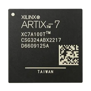
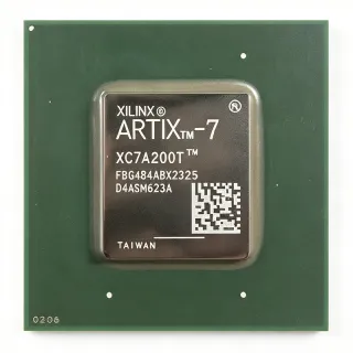
APA150-FG144I - 150K-Gate Flash FPGA | Microchip | 144-LBGA
MPN: APA150-FG144I ✓ 啟用中APA150-FG144I 概覽
A field-programmable gate array, or FPGA, is a programmable-logic semiconductor whose internal digital circuits can be configured after fabrication. FPGAs occupy a position between fixed-function ASICs and software-programmable processors. Unlike a mask-programmed ASIC, an FPGA can be reconfigured during development or field updates. Unlike an SRAM FPGA, the APA150 uses embedded nonvolatile flash, so its configuration is retained without continuously rewriting a volatile memory cell.
The APA150-FG144I provides 150K system gates and 100 I/Os in a compact 144-ball surface-mount package. Its nonvolatile configuration supports designs requiring persistent logic at power-up without an external configuration PROM. According to Microchip's ProASICPLUS information, reprogrammability, nonvolatility, live-at-power-up behavior, and an ASIC-oriented design flow are central family features.
The flash-based architecture also differentiates the device from SRAM FPGA families. Microchip states that ProASICPLUS devices do not produce the power-on current surges and high-current transitions associated with SRAM configuration memories. Their lower dynamic power behavior is useful in battery-operated and power-sensitive equipment, where startup behavior and sustained energy use can determine practical operating time.
Typical uses include industrial control and instrumentation, embedded protocol bridging, sensor acquisition, power-management sequencing, communications infrastructure, and compact embedded systems requiring nonvolatile programmable logic. The APA150 family is particularly suitable when designers want the flexibility of field programming while avoiding the recurring configuration-memory overhead of SRAM-based FPGAs.
Layout should be planned around the 144-ball grid, power distribution, decoupling, configuration access, and programmed I/O standards. Confirm the exact ball assignments, supported I/O voltage combinations, configuration pins, clock requirements, and programming interface in the manufacturer datasheet before releasing the PCB or production design.
This product overview combines the identified 150K-gate, 100-I/O, and 144-LBGA characteristics with practical guidance for FPGA selection, pin-compatible family alternatives, comparison tables, and design considerations that support faster engineering decisions.
直接替換替代品,適用於 APA150-FG144I — 相同封裝,腳位對腳位相容。需重新設計 PCB 的不同封裝零件不列入。
此系列的變體
與下列產品可直接替換的同系列型號: APA150-FG144I (相同外形與佔位) — 差異在於 Device Type, User I/O Count.
APA150-FGG144I
✅ 直接替換 ⚠️ 規格未經驗證📋 參考替代品(不在目錄中)
APA150-FG144
✅ 直接替換 ⚠️ 規格未經驗證聯絡詢價
查看資料表 →APA150-FGG144
✅ 直接替換 ⚠️ 規格未經驗證📋 參考替代品(不在目錄中)
APA150-FG144I 最大額定值與電氣特性
| Device Type | ProASICPLUS field-programmable gate array |
| Programmable Logic Capacity | 150K system gates |
| User I/O Count | 100 I/Os |
| Configuration Memory Technology | Nonvolatile flash |
| Power-Up Behavior | Live at power-up |
| Programmability | Reprogrammable |
| Package Type | 144-LBGA square surface-mount package |
| Terminal Count | 144 balls |
| Package Dimensions | 13 mm x 13 mm |
| 安裝類型 | Surface mount |
| Temperature Grade | Industrial grade |
| 工作溫度 | -40 °C to +85 °C |
| 供應電壓 | 2.3 V to 2.7 V |
| Power Consumption Characteristic | Lower dynamic power consumption than SRAM FPGAs |
| Power-On Current Surge | No SRAM-style power-on configuration current surge |
| Design Flow | ASIC-oriented FPGA design flow |
APA150-FG144I 13 mm x 13 mm 腳位配置指南
APA150-FG144I(13 mm x 13 mm 封裝)的腳位配置。 此數位 IC 包含 GPIO、通訊介面(UART、SPI、I2C)與電源腳位。替代腳位功能與配置選項請參閱製造商資料表。對嵌入式系統設計與 PCB 佈局至關重要。

無詳細腳位定義資料: APA150-FG144I.
請參閱 資料表 以查看完整腳位配置。
典型應用
APA150-FG144I 適用於 6 應用s: Industrial Control and Automation, Sensor Acquisition and Signal Conditioning, Embedded Protocol Bridging, Power Management Sequencing, Battery-Powered Embedded Instruments, Communications and Network Interface Control.
Industrial Control and Automation
The APA150-FG144I fits industrial controllers that combine deterministic control logic with a moderate number of external interfaces. Its 150K system gates provide capacity for sequencing, state-machine, and protocol-handling blocks, while 100 I/Os support sensors, actuators, status indicators, and communication transceivers. Nonvolatile flash configuration and live-at-power-up behavior allow the controller to resume its configured logic after power restoration without a separate volatile configuration source. The industrial temperature range of -40 °C to +85 °C and the 144-LBGA surface-mount package support compact control boards operating across factory environments.
Sensor Acquisition and Signal Conditioning
The APA150-FG144I can coordinate sensor acquisition, digital filtering, thresholding, and data formatting in compact instrumentation. Its 100 I/Os provide connections for sensor outputs, reference signals, switches, status LEDs, and data-capture interfaces, while the 150K system gates can host parallel acquisition logic, control state machines, and communication formatting. Because configuration is retained in nonvolatile flash, calibration or control logic can remain active at power-up without an SRAM configuration reload. The 2.3 V to 2.7 V operating supply also aligns with low-voltage signal-chain designs, subject to the specific I/O and core voltage requirements in the datasheet.
Embedded Protocol Bridging
The APA150-FG144I is appropriate for protocol converters, legacy interface adapters, and embedded communications controllers that need programmable logic close to the physical interface. With 150K system gates and 100 I/Os, it can combine serial framing, CRC generation, buffering, timeout management, and parallel-to-serial conversion in one device. Live-at-power-up operation allows the bridging function to become operational rapidly after power application, while nonvolatile flash retains the programmed protocol logic. The 144-LBGA package accommodates the required power, ground, clock, configuration, and I/O balls without moving to a larger board outline.
Power Management Sequencing
The APA150-FG144I can act as a configurable supervisor and sequencing controller in power systems. Its programmable logic can monitor enables, fault signals, and rail-status inputs, then generate ordered control actions for external regulators and load switches. Flash-based configuration provides deterministic startup behavior and avoids the large power-on configuration transitions associated with SRAM FPGA families. With 100 I/Os, the controller can support multiple monitored rails, discrete fault inputs, relay or load-control outputs, and status reporting. The -40 °C to +85 °C industrial range suits equipment exposed to uncontrolled ambient conditions.
Battery-Powered Embedded Instruments
The APA150-FG144I supports battery-powered instruments where configuration retention and operating efficiency are important. Nonvolatile flash preserves the programmed logic without a continuously powered SRAM configuration cell, and live-at-power-up operation permits rapid entry into the intended function after power is restored. Microchip identifies ProASICPLUS devices as suitable for power-sensitive applications with lower dynamic power consumption than SRAM FPGAs. The 100 I/Os can connect sensors, buttons, displays, and low-power communications, although overall battery life still depends on clocking, I/O activity, external component loading, and the power-management architecture selected for the complete product.
Communications and Network Interface Control
The APA150-FG144I can implement dedicated interface-control logic around network, storage, or industrial communications equipment. Its 150K system gates support parallel data movement, packet filtering, FIFO control, and protocol state machines, while 100 I/Os provide access to buses and status signals. Live-at-power-up operation is valuable in systems that must initialize communication logic immediately after supply stabilization, and nonvolatile configuration preserves a stable function across power cycles. In a 144-LBGA package, engineers must plan power and ground distribution carefully and confirm supported I/O standards, clocking, and timing for the selected external interface.
工程參考資料,適用於 APA150-FG144I — 比較、設計指引及合規資訊。
選型指南
與替代品比較
| 參數 | 本產品 | APA150-FGG144I | APA150-FG144 | APA150-FGG144 |
|---|---|---|---|---|
| Brand | Microchip Technology | Microchip Technology | Microchip Technology | Microchip Technology |
| Package | 144-LBGA (FBGA) | 144-LBGA (FBGA) | 144-LBGA (FBGA) | 144-LBGA (FBGA) |
| Device Type | ProASICPLUS flash FPGA | ProASICPLUS flash FPGA | ProASICPLUS flash FPGA | ProASICPLUS flash FPGA |
| Configuration Memory | Nonvolatile flash | Nonvolatile flash | Nonvolatile flash | Nonvolatile flash |
| Power-Up Behavior | Live at power-up | Live at power-up | Live at power-up | Live at power-up |
| Programming Method | ProASICPLUS flash programming workflow | ProASICPLUS flash programming workflow | ProASICPLUS flash programming workflow | ProASICPLUS flash programming workflow |
主要差異化特點
- Nonvolatile configuration with immediate startup behavior (對比SRAM-based FPGA designs)
- Moderate logic and interface capacity in a compact BGA (對比APA150-FG144)
- Same-family alternative simplifies qualification (對比APA150-FGG144I)
設計說明
Treat the 144-LBGA footprint as a dense BGA escape problem rather than a conventional perimeter-lead layout. Assign power and ground balls first, place adequate decoupling close to each supply pin, and route high-speed or sensitive nets through the shortest practical paths. Check the manufacturer ball-view convention against the CAD footprint, especially the pin-1 orientation, before fabrication. Because the device has 100 user I/Os among 144 balls, use the pin-description table to distinguish programmable I/O from power, configuration, clock, and ground positions.
Plan the power tree around the listed 2.3 V to 2.7 V supply range and the device's specific core and I/O requirements. Place bulk and high-frequency decoupling according to the manufacturer recommended circuit, provide a low-impedance return path for every ground ball, and isolate noisy switching nodes from sensitive programmable inputs. The flash architecture avoids SRAM-style power-on configuration surges, but the final board still needs controlled ramp time and adequate sequencing to protect device reliability.
Confirm configuration pins, programming interface signals, clock requirements, and dedicated test functions from the manufacturer pin table before committing the schematic. Match the exact FG144 ordering variant and its package drawing to the PCB library. Avoid assigning I/O standards solely by ball availability: verify each voltage domain, drive strength, slew rate, and supported input or output type. This prevents a package-compatible substitution from creating electrical or timing incompatibility.
Do not treat the APA150-FG144, APA150-FGG144I, and APA150-FGG144 ordering codes as automatically interchangeable. The differences may involve speed grade, temperature grade, or package-related ordering conventions. Review the manufacturer device-selection table, timing specifications, and configuration identifiers for each exact MPN. Also verify the requested delivery format: the target is specified as a 144-LBGA industrial-grade device, and a tray is identified as the standard handling format.
合規資訊
RoHS, REACH, AEC-Q100, lead-free, halogen-free, and conflict-minerals status require confirmation from Microchip for the exact APA150-FG144I ordering code.