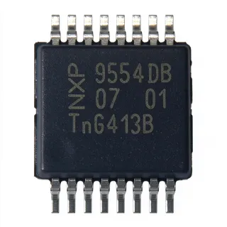
PCA9554DB - 8-Bit I2C I/O Expander, 5.5V | TI
MPN: PCA9554DB ✓ 啟用中PCA9554DB 概覽
An I/O expander is an interface IC that increases the number of input and output lines available to a microcontroller or other host processor. The PCA9554 belongs to the I2C interface-controller hierarchy: it connects through the two-line bidirectional bus using SCL and SDA, while its eight parallel pins can be configured individually as inputs or outputs. This makes it useful when a system needs remote control, monitoring, or signal-interface expansion without adding a larger microcontroller package.
The verified listing identifies weak pull-ups, an interrupt output, and configuration registers as defining features. Configuration registers allow the host to define each port direction and control output states, while the interrupt output provides a change notification mechanism for input events. The 2.3 V to 5.5 V operating range supports both low-voltage and conventional 5 V system rails, subject to the host and bus requirements.
The PCA9554DB is identified as a 16-SSOP I/O expander by DigiKey, with an operating bus frequency of 400 kHz. This combination of eight configurable I/O lines, interrupt support, and a compact surface-mount package makes the device suitable for embedded control, remote sensing, keypad or display interfaces, and small automation systems.
Designers should confirm the device address, pull-up implementation, electrical limits, and interrupt polarity against the manufacturer datasheet before finalizing a board. The verified data does not provide pin-level naming, output-current limits, or detailed timing values, so those parameters require verification rather than assumption.
直接替換替代品,適用於 PCA9554DB — 相同封裝,腳位對腳位相容。需重新設計 PCB 的不同封裝零件不列入。
此系列的變體
與下列產品可直接替換的同系列型號: PCA9554DB (相同外形與佔位) — 差異在於 Interrupt Output, Package.
PCA9554DB
✅ 直接替換聯絡詢價
查看資料表 →PCA9554ABS3,118
✅ 直接替換聯絡詢價
查看資料表 →TCA9554PWR
✅ 直接替換📋 參考替代品(不在目錄中)
TCA9554ADBR
✅ 直接替換📋 參考替代品(不在目錄中)
PCA9554DB 規格
| 功能 | 8-bit I2C/SMBus I/O expander with interrupt |
| Number of I/O Lines | 8 |
| Operating Voltage Range | 2.3 V to 5.5 V |
| 介面 | I2C/SMBus |
| Maximum Bus Frequency | 400 kHz |
| Configuration Registers | Present |
| Interrupt Output | Present |
| Weak Pull-Ups | Present |
| 封裝 | 16-pin SSOP |
| 安裝類型 | Surface mount |
| Device Class | General-purpose remote I/O expander |
| 輸出配置 | Individually configurable input/output ports |
| Bus Signals | SCL and SDA |
PCA9554DB 16-pin ssop 腳位配置指南
PCA9554DB(16-pin ssop 封裝)的腳位配置。 腳位編號、功能與連接圖定義於製造商資料手冊中。請參閱該手冊以取得確切的封裝尺寸與焊接指引。

無詳細腳位定義資料: PCA9554DB.
請參閱 資料表 以查看完整腳位配置。
典型應用
PCA9554DB 適用於 7 應用s: Microcontroller GPIO Expansion, Remote Sensor and Actuator Interface, Embedded Control Panel, Industrial Automation Module, Remote Monitoring and Control, LED and Indicator Control, Consumer and Communication Equipment.
Microcontroller GPIO Expansion
The PCA9554DB is useful when a microcontroller has too few direct pins for control and monitoring functions. Its eight configurable I/O ports operate through the I2C/SMBus interface at up to 400 kHz, allowing the host to read remote inputs and drive remote outputs while conserving package pins. The design should define port directions in the configuration registers and account for the device's interrupt output when an input change must wake the host.
推薦
Remote Sensor and Actuator Interface
PCA9554DB can place eight digital I/O lines behind an I2C connection between a controller and a remote circuit card. This arrangement is useful for reading discrete sensor outputs or driving relays, indicators, and other digital actuators when direct board-to-board GPIO routing is inconvenient. The 2.3 V to 5.5 V operating range supports mixed-voltage systems, but cable length, bus capacitance, pull-up values, grounding, and output drive must be validated for the selected remote load.
推薦
Embedded Control Panel
The eight ports can serve as an I2C-connected front panel interface for buttons, indicators, lamps, selectors, and status signals. A host microcontroller can scan inputs and update outputs over the same two-wire bus, reducing wiring compared with direct GPIO. The verified interrupt feature can reduce unnecessary polling when an input state changes, while the 400 kHz maximum bus rate supports compact embedded-control architectures when the total bus loading and firmware timing remain acceptable.
推薦
Industrial Automation Module
PCA9554DB is suitable for small automation modules that need a compact, addressable set of digital outputs and inputs. The device can connect discrete control signals to a microcontroller while the interrupt output provides an event path for changing input conditions. In an industrial enclosure, engineers should verify voltage tolerances, isolation requirements, surge protection, grounding, connector current limits, and the operating temperature range because those details are not provided in the supplied verified snippets.
推薦
Remote Monitoring and Control
The PCA9554DB can monitor remote digital conditions and return control outputs through the host's I2C bus. This pattern is useful in equipment where a central controller needs distributed status points without routing every signal back as a direct GPIO. The interrupt output can signal activity, but system timing depends on the host firmware, bus clock, pull-up network, and whether the remote signals are slower than the 400 kHz bus capability. Input thresholds and output current must be confirmed from the full datasheet.
推薦
LED and Indicator Control
Eight output ports from PCA9554DB can control groups of LEDs, status lamps, or indicator signals when the host lacks sufficient direct output pins. The I2C connection reduces the number of dedicated microcontroller pins, while configuration registers define which ports are outputs. The designer must check the device's output drive limits and supply requirements before directly loading LEDs or other devices; the supplied data confirms eight I/O lines and configurable ports but does not specify per-pin output current.
推薦
Consumer and Communication Equipment
PCA9554DB can add configurable digital lines in compact consumer, communications, or accessory hardware where the main controller is connected to I2C. Its 2.3 V to 5.5 V range accommodates common low-voltage and 5 V rails, and the 16-pin SSOP package supports compact board layouts. Product-specific compliance, temperature, EMC, and output-loading requirements are not supplied in the verified data and must be evaluated separately rather than inferred from the interface function.
推薦
推薦產品摘要
工程參考資料,適用於 PCA9554DB — 比較、設計指引及合規資訊。
選型指南
與替代品比較
| 參數 | 本產品 | PCA9554A | TCA9554PWR | TCA9554ADBR | PCA9534DB |
|---|---|---|---|---|---|
| Brand | Texas Instruments | NXP Semiconductors | Texas Instruments | Texas Instruments | NXP Semiconductors |
| Package | 16-pin SSOP | 16-pin SSOP | TSSOP-16 | SSOP-16 | 16-pin SSOP |
| Interface | I2C/SMBus | I2C/SMBus | I2C/SMBus | I2C/SMBus | I2C/SMBus |
主要差異化特點
- Eight configurable remote I/O lines in a compact 16-pin SSOP package (對比PCA9554A)
- Explicit interrupt, configuration-register, and weak-pull-up features (對比PCA9534DB)
- I2C/SMBus operation up to 400 kHz (對比TCA9554PWR)
設計說明
Place the PCA9554DB close to the SCL and SDA routing and keep the I2C traces short and continuous. The verified device supports up to 400 kHz, but actual bus operation also depends on capacitance, pull-up resistance, trace length, and every peripheral on the bus. Confirm the complete pin names and exposed connections from the manufacturer datasheet before finalizing the footprint.
Design the 2.3 V to 5.5 V supply rail with appropriate local decoupling and verify the host and peripheral logic levels. Do not infer output-current capability from the eight-port description; the verified snippets do not provide per-pin drive limits, so loads such as LEDs or relay drivers must be checked against the full manufacturer datasheet.
Do not treat PCA9554 and PCA9554A as address-identical. The supplied NXP listing states that the devices have different addresses, so replacing one with the other can leave the host controller unable to communicate. Firmware, pull-up configuration, interrupt polarity, and the selected manufacturer must all be reviewed together.
Reserve test points for VCC, ground, SCL, SDA, the interrupt line, and all eight I/O signals. Keeping these points accessible helps validate bus rise time, port direction, and interrupt behavior during bring-up. If a remote cable or long trace is used, evaluate signal integrity and protection separately from the nominal 400 kHz specification.
合規資訊
The supplied verified snippets do not state RoHS, REACH, AEC-Q100, lead-free, halogen-free, or conflict-minerals status. No compliance claim should be inferred from the interface description.