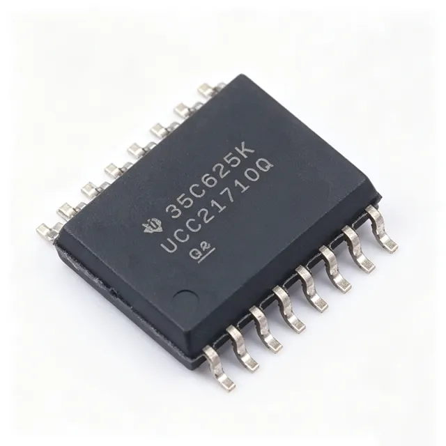
UCC21710-Q1 - 10A Isolated Gate Driver | Texas Instruments
MPN: UCC21710-Q1 ✓ 啟用中UCC21710-Q1 概覽
A gate driver is a power-management IC that converts low-voltage control signals from a microcontroller into high-current pulses to drive the gate of power transistors. In a system hierarchy, the gate driver sits between the controller and the power switch, providing isolation and signal amplification. The UCC21710-Q1 belongs to the isolated gate driver family, which adds galvanic isolation to protect low-voltage control circuitry from high-voltage transients.
Key features include: ±10 A peak source/sink current, 5700 Vrms reinforced isolation, single-channel operation, and input and output side UVLO. It supports overcurrent (OC) and short-circuit detection via shunt sensing, active Miller clamp to prevent spurious turn-on, fault reporting, and isolated analog-to-PWM sensing for temperature or voltage monitoring. These features provide comprehensive protection for SiC and IGBT switching.
The UCC21710-Q1 uses capacitive coupling for signal transfer, achieving high CMTI. It is AEC-Q100 qualified for automotive applications, meeting the reliability demands of HEV/EV traction inverters. The device's short-circuit clamping feature limits gate voltage to slightly above VDD, protecting semiconductors from gate-source/emitter overvoltage breakdown.
Typical applications include HEV/EV traction inverters, solar inverters, industrial motor drives, UPS, wind turbine converters, and railway traction. The high peak current and 1700-V rating allow it to directly drive large IGBT modules and SiC MOSFETs without external buffers. Its isolation enables safe operation in high-voltage DC-link systems.
When designing with this device, ensure proper bias supplies: UCC14240-Q1 is a recommended isolated power supply for the output side. Pay attention to gate loop inductance and maintain adequate PCB spacing for reinforced isolation. The active Miller clamp must be connected to the gate to prevent high dV/dt-induced turn-on.
直接替換替代品,適用於 UCC21710-Q1 — 相同封裝,腳位對腳位相容。需重新設計 PCB 的不同封裝零件不列入。
此系列的變體
與下列產品可直接替換的同系列型號: UCC21710-Q1 (相同外形與佔位) — 差異在於 Package.
快速比較工具 — 選擇替代零件進行並排比較:
UCC21710DWR
📋 參考替代品(不在目錄中)
UCC21750QDWRQ1
📋 參考替代品(不在目錄中)
UCC21732QDWRQ1
📋 參考替代品(不在目錄中)
UCC21736QDWRQ1
📋 參考替代品(不在目錄中)
ISO5852SQDWRQ1
📋 參考替代品(不在目錄中)
UCC21710-Q1 最大額定值與電氣特性
| Output Current | ±10 A (peak source/sink) |
| Isolation Voltage | 5700 Vrms (reinforced) |
| Number of Channels | 1 |
| 封裝 | 16-SOIC (D) |
| Switching Voltage | Up to 1700 V (SiC/IGBT) |
| Technology | Capacitive Coupling |
| Automotive Grade | Yes (AEC-Q100) |
| Input Type | Digital |
| 安裝類型 | Surface Mount |
UCC21710-Q1 16-soic (d) 腳位配置指南
UCC21710-Q1(16-soic (d) 封裝)的腳位配置。 此功率元件具有閘極、汲極與源極端子。對於非極性封裝,請參閱製造商資料表以取得確切的第 1 腳方向與佈局詳細資訊。常見應用包括電源設計、馬達驅動與負載切換。

無詳細腳位定義資料: UCC21710-Q1.
請參閱 資料表 以查看完整腳位配置。
典型應用
UCC21710-Q1 適用於 6 應用s: HEV/EV Traction Inverters, Solar Inverters, Industrial Motor Drives, UPS and Power Supplies, Wind Turbine Converters, Railway Traction.
HEV/EV Traction Inverters
The UCC21710-Q1 provides ±10 A peak source/sink current to drive SiC MOSFETs and IGBTs in high-voltage traction inverters up to 1700 V. Its high CMTI ensures reliable switching in noisy automotive environments, while the active Miller clamp prevents spurious turn-on. The isolated analog-to-PWM sensor enables temperature or voltage sensing, aiding real-time diagnostics. Used in the half-bridge stage, it interfaces with the MCU via an isolated PWM signal. Compared to standard drivers, the UCC21710-Q1 reduces switching losses and enhances system robustness, critical for traction inverters demanding high efficiency and functional safety.
推薦
Solar Inverters
In grid-tied solar inverters, the UCC21710-Q1 drives high-power SiC MOSFETs in the DC-DC converter and inverter stages. Its 5700 Vrms isolation provides safety isolation between the DC bus and control side. The overcurrent and short-circuit protection with shunt sensing allows fast fault shutdown, preventing semiconductor damage. The high peak current ensures rapid gate transitions, reducing switching losses at high frequencies. The device's UVLO on both input and output sides ensures proper startup and shutdown sequencing. With its robust CMTI, it handles high dV/dt switching, making it ideal for solar MPPT and DC-AC conversion stages.
推薦
Industrial Motor Drives
For industrial motor drives, UCC21710-Q1 reliably drives IGBTs in three-phase inverters. Its 1700-V rating suits medium-voltage motor applications, while the ±10 A current capability charges large gate capacitances quickly. The isolated analog sensor output allows current and temperature monitoring without extra sensors. The driver's fault reporting with active Miller clamp reduces EMI and prevents false triggering. The SOIC-16 package simplifies board layout. Additionally, the input-side UVLO ensures the controller is ready before enabling the power stage. This reduces system complexity and lowers overall cost compared to discrete driver solutions.
推薦
UPS and Power Supplies
In high-power UPS and switched-mode power supplies, UCC21710-Q1 isolates and drives IGBTs or SiC MOSFETs in power factor correction (PFC) and inverter stages. The driver's 5700 Vrms isolation ensures safe operation in high-voltage DC-link applications. Its fast overcurrent and short-circuit detection with shunt sensing provides comprehensive protection. The device's high CMTI maintains signal integrity under high slew-rate switching. The isolated analog-to-PWM sensor simplifies temperature compensation in precision power supplies. With a wide supply range, it adapts to various bias configurations, reducing design effort.
推薦
Wind Turbine Converters
Wind turbine converters typically use high-power IGBTs in back-to-back converters. UCC21710-Q1 drives the generator-side and grid-side converters, handling voltages up to 1700 V. Its ±10 A peak current enables fast switching of large modules, reducing switching losses. The active Miller clamp prevents shoot-through in high dV/dt conditions. The driver's isolated analog sensing supports temperature monitoring for thermal management. With automotive-grade qualification, it provides reliability in harsh outdoor environments. The SOIC-16 package allows compact converter design, crucial for wind turbine nacelles where space is limited.
推薦
Railway Traction
Railway traction systems require robust drives for IGBTs in 1500-3000 V DC converters. UCC21710-Q1 provides reinforced isolation to meet safety standards and supports up to 1700 V per rail. Its high CMTI ensures reliable data transmission under severe electromagnetic interference from traction motors. The driver's overcurrent and short-circuit protection with shunt sensing detects faults rapidly, protecting expensive IGBT modules. The SOIC-16 package simplifies integration into compact converter units. Its AEC-Q100 qualification is suitable for railway rolling stock, which has strict reliability requirements.
推薦
推薦產品摘要
工程參考資料,適用於 UCC21710-Q1 — 比較、設計指引及合規資訊。
選型指南
與替代品比較
| 參數 | 本產品 | UCC21710DWR | UCC21750QDWRQ1 | UCC21732QDWRQ1 | UCC21736QDWRQ1 | ISO5852SQDWRQ1 |
|---|---|---|---|---|---|---|
| Package | 16-SOIC (D) | 16-SOIC (D) - same | 16-SOIC (D) - same | 16-SOIC (D) - same | 16-SOIC (D) - same | 16-SOIC (D) - same |
| Brand | Texas Instruments | Texas Instruments | Texas Instruments | Texas Instruments | Texas Instruments | Texas Instruments |
| Peak Output Current | ±10 A | ±10 A | ±10 A | ±10 A | ±10 A | ≤2.5 A |
| Number of Channels | 1 | 1 | 1 | 1 | 1 | 1 |
| Automotive Grade | Yes (AEC-Q100) | No | Yes | Yes | Yes | Yes |
主要差異化特點
- Higher peak output current (±10 A) (對比ISO5852SQDWRQ1)
- Integrated overcurrent and shunt sensing (對比UCC21750QDWRQ1)
- Automotive-grade qualification with 1700 V rating (對比UCC21710DWR)
設計說明
At high switching frequencies, gate drive power dissipation can be significant. Calculate the average gate drive current from total gate charge Qg and frequency: I_avg = Qg * f. The UCC21710-Q1's ±10 A peak current ensures low propagation delay, but the IC self-heating is mainly from quiescent and switching losses. Ensure adequate copper area for the SOIC-16 package thermal pad, and keep the driver close to the gate to minimize parasitic inductance.
For high CMTI performance, minimize stray capacitance between input and output sides. Place the isolation barrier as clean as possible, and use appropriate creepage distances per IEC 60664 for the operating voltage. Keep gate loops short and use a dedicated driver power supply (e.g., UCC14240-Q1) to avoid noise.
Avoid exceeding the absolute maximum ratings of the input and output supply voltages. Maintain proper UVLO threshold margins. Also, the active Miller clamp is essential when using SiC MOSFETs to prevent false turn-on during high dV/dt transitions; ensure the clamp is correctly connected to the gate.
合規資訊
AEC-Q100 qualification implied by -Q1 suffix. RoHS and other compliance data not explicitly provided in verified web data; verify with manufacturer.







