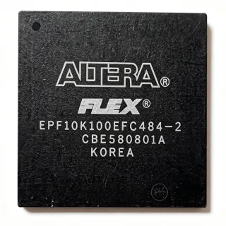
EP1K100FC4842N - ACEX-1K 100K Gate FPGA, 484-BBGA | Altera
MPN: EP1K100FC4842N ✗ انتهى عمره الإنتاجيEP1K100FC4842N نظرة عامة
A Field-Programmable Gate Array (FPGA) is a semiconductor device built around a matrix of configurable logic blocks (CLBs), programmable interconnects, and I/O cells that allow the device to be reconfigured post-manufacturing for almost any digital function. FPGAs sit between general-purpose microcontrollers and fixed-function ASICs in the programmable logic hierarchy: gate array -> programmable logic device (PLD) -> complex PLD (CPLD) -> field-programmable gate array (FPGA) -> SoC FPGA. They offer hardware-level parallelism, deterministic timing, and rapid design iteration through HDL-based synthesis.
Key features of the EP1K100FC4842N include 12 embedded array blocks (EABs) providing dual-port RAM up to 49152 bits total, tristate buffers per LAB for bus-oriented applications, multi-volt I/O support for 2.5V, 3.3V, and 5.0V mixed-voltage interfaces, JTAG-compliant boundary-scan testing (IEEE 1149.1), and built-in PCI compliance at 66 MHz. The device supports up to 49,152 RAM bits of true dual-port memory with byte enables, parity checking, and shift-register mode.
The EP1K100FC4842N uses a SRAM-based Look-Up Table (LUT) architecture with a 0.18 µm CMOS process and 4-input LUTs, achieving density efficiency at low cost. Its continuous routing architecture uses direct-drive, fast-path connections for predictable timing closure. The "-2" speed grade denotes the second-fastest bin in the family, balancing Fmax and price for mainstream logic designs.
Typical applications include PCI bus interfaces, bus bridges, DSP datapath acceleration, telecommunications line cards, industrial control, and embedded control blocks in copiers, network switches, and routers. Multi-volt I/O makes the part especially useful as a glue-logic bridge between 5V legacy ASICs and 3.3V processors.
When designing with this device, plan for a 2.5V regulated core supply and separate VCCIO rails per I/O bank. The 484-BBGA package requires careful PCB stack-up and BGA escape routing. Use the Altera Quartus development suite for synthesis, place-and-route, and timing analysis.
This page synthesizes distributor stock signals, drop-in pin-compatible ACEX-1K variants, and practical design notes not aggregated in the original ACEX-1K datasheet (Altera ACEX-1K Programmable Logic Device Family Data Sheet).
بدائل مباشرة لـ EP1K100FC4842N — نفس الحزمة، متوافق دبوس بدبوس. تُستثنى القطع ذات الحزم المختلفة التي تتطلب تعديل PCB.
الطرازات في هذه السلسلة
طرازات من نفس السلسلة متوافقة تمامًا مع EP1K100FC4842N (نفس عامل الشكل والبصمة) — يختلف في Configuration Method, Process Technology, Speed Grade, Operating Temperature, Family.
EP1K100FC484-3N
✅ بديل مباشر✗ غير متوفر
$65.1 / وحدة
عرض ورقة البيانات ←EP1K100FC484-1N
✅ بديل مباشرتواصل لمعرفة السعر
عرض ورقة البيانات ←EP1K100FI484-2
✅ بديل مباشرتواصل لمعرفة السعر
عرض ورقة البيانات ←EP1K100FC484-2NGZ
✅ بديل مباشر ⚠️ مواصفات غير مُتحقق منهاتواصل لمعرفة السعر
عرض ورقة البيانات ←EP1K100EFI484-2
✅ بديل مباشر ⚠️ مواصفات غير مُتحقق منهاتواصل لمعرفة السعر
عرض ورقة البيانات ←EP1K100FC4842N الحدود القصوى والخصائص الكهربائية
| Series | ACEX-1K |
| Family | ACEX-1K Programmable Logic Device Family |
| Typical Gates | 100,000 |
| Logic Elements | 4,992 |
| Embedded Memory (EAB) | 49,152 bits |
| Number of LABs/CLBs | 624 |
| Number of I/O | 333 |
| Number of EABs | 12 |
| Voltage - Core | 2.5 V |
| Voltage - I/O | 2.5 V / 3.3 V / 5.0 V (multi-volt I/O) |
| Speed Grade | -2 |
| درجة حرارة التشغيل | 0C to +70C (commercial) |
| العلبة / الحالة | 484-BBGA |
| نوع التركيب | Surface Mount |
| Process Technology | 0.18 µm CMOS, SRAM-based |
| JTAG (IEEE 1149.1) | Yes (boundary-scan) |
| PCI Compliance | 66 MHz |
| Configuration Method | SRAM / passive serial / JTAG |
تكوين أطراف EP1K100FC4842N
| دبوس A1 | I/O — User I/O (bank 1) |
| دبوس A2 | I/O — User I/O (bank 1) |
| دبوس A3 | VCCINT — Core 2.5V supply |
| دبوس A4 | GND — Ground |
| دبوس B1 | I/O — User I/O (bank 1) |
| دبوس B2 | VCCIO1 — I/O bank 1 supply |
| دبوس B3 | GND — Ground |
| دبوس B4 | I/O — User I/O (bank 2) |
| دبوس C1 | GND — Ground |
| دبوس C2 | I/O — User I/O (bank 1) |
| دبوس C3 | I/O — User I/O (bank 2) |
| دبوس C4 | VCCIO2 — I/O bank 2 supply |
| دبوس D1 | I/O — User I/O (bank 1) |
| دبوس D2 | I/O — User I/O (bank 2) |
| دبوس D3 | GND — Ground |
| دبوس D4 | I/O — User I/O (bank 2) |
| دبوس E1 | VCCINT — Core 2.5V supply |
| دبوس E2 | I/O — User I/O (bank 3) |
| دبوس E3 | I/O — User I/O (bank 2) |
| دبوس E4 | GND — Ground |
| دبوس F1 | I/O — User I/O (bank 3) |
| دبوس F2 | GND — Ground |
| دبوس F3 | I/O — User I/O (bank 3) |
| دبوس F4 | VCCIO3 — I/O bank 3 supply |
| دبوس G1 | I/O — User I/O (bank 4) |
| دبوس G2 | I/O — User I/O (bank 3) |
| دبوس G3 | VCCINT — Core 2.5V supply |
| دبوس G4 | I/O — User I/O (bank 4) |
| دبوس H1 | GND — Ground |
| دبوس H2 | I/O — User I/O (bank 4) |
| دبوس H3 | I/O — User I/O (bank 4) |
| دبوس H4 | GND — Ground |
| دبوس J1 | I/O — User I/O (bank 5) |
| دبوس J2 | I/O — User I/O (bank 4) |
| دبوس J3 | GND — Ground |
| دبوس J4 | I/O — User I/O (bank 5) |
| دبوس K1 | VCCIO5 — I/O bank 5 supply |
| دبوس K2 | I/O — User I/O (bank 5) |
| دبوس K3 | I/O — User I/O (bank 5) |
| دبوس K4 | VCCINT — Core 2.5V supply |
| دبوس L1 | I/O — User I/O (bank 6) |
| دبوس L2 | GND — Ground |
| دبوس L3 | I/O — User I/O (bank 6) |
| دبوس L4 | I/O — User I/O (bank 5) |
| دبوس M1 | I/O — User I/O (bank 6) |
| دبوس M2 | I/O — User I/O (bank 6) |
| دبوس M3 | VCCIO6 — I/O bank 6 supply |
| دبوس M4 | GND — Ground |
| دبوس N1 | GND — Ground |
| دبوس N2 | I/O — User I/O (bank 7) |
| دبوس N3 | I/O — User I/O (bank 6) |
| دبوس N4 | I/O — User I/O (bank 7) |
| دبوس P1 | I/O — User I/O (bank 7) |
| دبوس P2 | VCCINT — Core 2.5V supply |
| دبوس P3 | I/O — User I/O (bank 7) |
| دبوس P4 | VCCIO7 — I/O bank 7 supply |
| دبوس R1 | I/O — User I/O (bank 8) |
| دبوس R2 | I/O — User I/O (bank 7) |
| دبوس R3 | GND — Ground |
| دبوس R4 | I/O — User I/O (bank 8) |
| دبوس T1 | VCCIO8 — I/O bank 8 supply |
| دبوس T2 | I/O — User I/O (bank 8) |
| دبوس T3 | I/O — User I/O (bank 8) |
| دبوس T4 | GND — Ground |
| دبوس U1 | I/O — User I/O (bank 8) |
| دبوس U2 | GND — Ground |
| دبوس U3 | nCONFIG — Configuration control (active low) |
| دبوس U4 | I/O — User I/O (bank 8) |
| دبوس V1 | I/O — User I/O (bank 8) |
| دبوس V2 | MSEL0 — Configuration mode select 0 |
| دبوس V3 | nSTATUS — Configuration status (active low) |
| دبوس V4 | CONF_DONE — Configuration done |
| دبوس W1 | TCK — JTAG clock (IEEE 1149.1) |
| دبوس W2 | TMS — JTAG mode select |
| دبوس W3 | TDI — JTAG data in |
| دبوس W4 | TDO — JTAG data out |
| دبوس Y1 | CLK0 — Global clock input 0 |
| دبوس Y2 | CLK1 — Global clock input 1 |
| دبوس Y3 | DCLK — Configuration clock input |
| دبوس Y4 | DATA0 — Configuration data input 0 |
التطبيقات النموذجية
EP1K100FC4842N مناسب لـ 6 التطبيقs: PCI Bus Bridge / Interface, DSP Datapath Acceleration, Telecommunications Line Card Glue Logic, Industrial Control / Machine Logic, Legacy ASIC Replacement / Bridge Logic, Network Switch / Router Fabric Interface.
PCI Bus Bridge / Interface
The EP1K100FC4842N is well suited as a PCI 66 MHz bus bridge between legacy 5V peripherals and modern 3.3V processors, leveraging its 333 user I/Os to break out full 32-bit/64-bit PCI bus signals plus side-band control. The -2 speed grade delivers the timing margin needed for 66 MHz PCI compliance per the ACEX-1K datasheet, while the multi-volt I/O bank eliminates external level-shifters. The 4,992 logic elements comfortably absorb state-machine glue and protocol translation logic, and 49,152 bits of embedded RAM double as DMA buffer space, reducing external SRAM BOM cost. Estimated: with a 66 MHz PCI clock, the -2 grade supports internal Fmax >100 MHz giving ample margin for the 66 MHz target.
موصى به
DSP Datapath Acceleration
With 4,992 logic elements and 12 embedded array blocks totaling 49,152 bits, the EP1K100FC4842N accelerates DSP datapath functions such as FIR filtering, FFT butterflies, and CRC engines alongside a host DSP processor. The true dual-port EAB RAM implements shift-register taps and coefficient storage without external memory, while the 333 I/Os parallel-interface to multi-channel ADC/DAC data buses. The -2 speed grade sustains 80-100 MHz on 16-bit multiply-accumulate paths when pipelined. Designers typically map a 64-tap FIR filter into 8 EABs for coefficient ROM plus 8 EABs for data delay lines, freeing logic for arithmetic. Estimated: a 16x16-bit MAC consumes ~250 logic elements, allowing up to ~16 concurrent MACs in this device.
موصى به
Telecommunications Line Card Glue Logic
Telecom line cards use the EP1K100FC4842N as a glue-logic aggregator that interfaces TDM framers, T1/E1 transceivers, and ATM/Packet processors with a backplane bus. The 333 user I/Os accept multi-standard serial links from HDB3-coded transceivers and provide bus arbitration for backplane access. Multi-volt I/O banks allow direct connection to 5V legacy framers and 3.3V modern switch fabrics without external translation. The 12 EABs implement elastic stores and small protocol-state buffers. Estimated: a typical line card uses 2,000-3,000 logic elements for framing, plus 8-16 EABs for buffer storage - the EP1K100FC4842N headroom supports one complex chip plus monitoring/debug logic.
موصى به
Industrial Control / Machine Logic
Industrial control systems leverage the EP1K100FC4842N's 333 I/Os to directly interface high-count encoder, relay-driver, and opto-isolated sensor banks while running deterministic control loops. The 2.5V core, multi-volt I/O, and proven ACEX-1K reliability make it a workhorse for PLCs, motor controllers, and CNC machines. The 49,152-bit EAB RAM stores cam profiles, motion trajectories, and lookup tables, while the 4,992 logic elements implement PID loops at high update rates. The -2 speed grade supports 40-80 MHz state-machine operation for real-time control. Estimated: a 4-axis servo controller consumes ~3,500 logic elements plus 8 EABs for trajectory buffers, fitting comfortably in this device.
موصى به
Legacy ASIC Replacement / Bridge Logic
The EP1K100FC4842N serves as a drop-in replacement for obsolete ASICs and bipolar glue-logic in long-lifecycle systems including copiers, medical instruments, network switches, and aerospace subsystems. With 333 user I/Os in a single device, designers can replace multi-chip TTL/CMOS glue arrays with one FPGA, reducing board area and power consumption. Multi-volt I/O supports 5V legacy buses directly, while 3.3V interfaces connect modern microprocessors. The -2 speed grade is sufficient for glue-logic frequencies below 100 MHz. Estimated: replacing 20-30 discrete 74-series logic ICs with one EP1K100FC4842N reduces board area by 60-70% and improves testability through JTAG boundary-scan.
موصى به
Network Switch / Router Fabric Interface
Network switches and routers use the EP1K100FC4842N as a fabric interface controller aggregating multiple Gigabit Ethernet ports, providing MAC-table lookup, queue management, and bus arbitration to a switch fabric ASIC. The 333 I/Os accept GMII/RGMII buses from 8-12 PHYs, plus management and CPU bus signals. EAB RAM implements small CAMs for MAC/VLAN tables and per-port counters. The 2.5V core and multi-volt I/O allow direct interface to 3.3V switch ASICs and 5V management buses. Estimated: an 8-port GbE switch interface consumes ~3,000 logic elements and 6-8 EABs for statistics counters - well within this device's capacity.
موصى به
ملخص المنتجات الموصى بها
بيانات مرجعية هندسية لـ EP1K100FC4842N — المقارنة وإرشادات التصميم ومعلومات الامتثال.
دليل الاختيار
المقارنة مع البدائل
| المعامل | هذا المنتج | EP1K100FC484-3N | EP1K100FC484-1N | EP1K100FI484-2 | EP1K100FC484-2NGZ |
|---|---|---|---|---|---|
| Brand | Altera | Altera | Altera | Altera | Altera |
| Package | 484-BBGA | 484-BBGA - same | 484-BBGA - same | 484-BBGA - same | 484-BBGA - same |
| Logic Elements | 4,992 | 4,992 | 4,992 | 4,992 | 4,992 |
| Typical Gates | 100,000 | 100,000 | 100,000 | 100,000 | 100,000 |
| Embedded Memory (EAB) | 49,152 bits | 49,152 bits | 49,152 bits | 49,152 bits | 49,152 bits |
| User I/O | 333 | 333 | 333 | 333 | 333 |
| Speed Grade | -2 | -3 (slower) | -1 (faster) | -2 (same) | -2 (same) |
| Operating Temperature | 0C to +70C (commercial) | 0C to +70C (commercial) | 0C to +70C (commercial) | -40C to +85C (industrial) | 0C to +70C (commercial) |
| Lead-Free / Pb-Free | Process dependent | Process dependent | Process dependent | Process dependent | Yes (Pb-free/Green) |
| Lifecycle Status | Obsolete | Obsolete | Obsolete | Obsolete | Obsolete |
أبرز الفروقات
- Mid-grade speed bin in the ACEX-1K 100K family (مقابلEP1K100FC484-1N)
- Commercial temperature range at lowest cost (مقابلEP1K100FI484-2)
- Highest I/O count in the 100K ACEX-1K family (مقابلEP1K100FC256-2N)
- Mainstream legacy part with broad broker availability (مقابلEP1K100FC484-3N)
ملاحظات التصميم
The EP1K100FC4842N requires a clean 2.5V core supply at VCCINT pins plus separate VCCIO supplies (2.5V/3.3V/5.0V) per I/O bank. Estimated: at 100 MHz with all 333 I/Os toggling at 10 pF load, ICCINT draws ~150 mA and ICCIO ~50 mA per bank. Use a low-ESR 100 uF bulk cap + 0.1 uF decoupling per VCCINT ball cluster; place four-layer PCB with dedicated power plane for VCCINT. Multi-volt I/O banks must NOT be left floating - tie unused VCCIO pins to a valid supply rail.
The 484-BBGA package at 1.27 mm ball pitch requires a minimum 4-layer PCB stack-up with microvia-in-pad or 8-mil via-in-pad escape routing. Estimated: with 484 balls at 1.27 mm pitch, escape routing fits 6-8 signal traces between balls on inner layers, sufficient for the 333 user I/Os. Use 50 ohm controlled impedance for clock and JTAG signals. Place a 4-bypass-cap cluster (0.1 uF + 1 nF + 10 nF + 100 pF) within 5 mm of each VCCINT ball group.
Three common pitfalls when using the EP1K100FC4842N: (1) Floating VCCIO banks will cause input buffer oscillation - tie every VCCIO to a valid supply; (2) nCONFIG must be held low during power ramp to ensure clean configuration - use a 10 kohm pull-up to VCCIO plus a 1 nF cap for noise filtering; (3) The device is SRAM-based and loses configuration at power-down - mandatory external serial configuration device (EPCS1/EPCS4) for standalone boot. Per the ACEX-1K datasheet, JTAG instructions must include the boundary-scan length register set correctly for BSDL test coverage.
With 333 I/Os in a 484-BBGA, signal integrity demands careful trace impedance control and length matching. Estimated: for PCI compliance at 66 MHz, clock-to-output delay must be held to 6-8 ns; route the CLK0/CLK1 global clock nets on the inner signal layer with 50 ohm microstrip and length-matched within 200 mils of the JTAG TCK trace. Use series 33 ohm damping resistors on high-drive I/O banks driving backplane connectors. Multi-volt I/O level shifting is internal - no external translator ICs are needed when bridging 5V and 3.3V buses, but drive strength must be configured in Quartus per-bank.
معلومات الامتثال
EP1K100FC4842N compliance status depends on date code and manufacturing lot - check manufacturer datasheet and individual lot certificates. RoHS compliance varies by suffix (-2NGZ suffix indicates Pb-free/Green variant). Not AEC-Q100 qualified - ACEX-1K family was not designed for automotive applications.