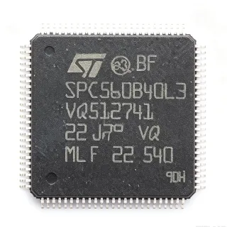
STM32G474VET3 - 170MHz Cortex-M4F MCU 512KB LQFP-100 | ST
MPN: STM32G474VET3 ✓ نشطSTM32G474VET3 نظرة عامة
An Arm Cortex-M4 microcontroller is a 32-bit RISC processor core designed for deterministic real-time embedded control, with single-precision floating-point, DSP extensions, and a tightly-coupled NVIC for low-latency interrupt handling. Within the broader taxonomy, this part belongs to the MCU -> microcontroller -> semiconductor category, and to ST's STM32G4 series, which adds a CORDIC math accelerator and FMAC filter-math accelerator that offload trigonometric and FIR/IIR computations from the CPU for digital power conversion and motor-control loops.
Key features include five 12-bit ADCs sampling at 4 MSPS with hardware oversampling to 16-bit effective resolution, four 12-bit DAC channels, seven comparators, six op-amps with programmable gain, four 184 ps resolution high-resolution timer channels, USB 2.0 Full-speed with PHY, CAN-FD, three SPI, three I2C, two UART/LPUART, an SDMMC package interface, and a math accelerator block (CORDIC + FMAC). The 100-LQFP exposes 81 GPIO across five voltage-tolerant 5V-tolerant I/O banks.
The STM32G474 architecture pairs the Cortex-M4F core with ST's adaptive real-time ART Accelerator and a multi-bank Flash controller that delivers zero-wait-state execution from Flash at 170 MHz. The integrated op-amps and comparators are tightly coupled to the high-resolution timer to form current-shunt and BEMF sensing loops without external analog ICs, enabling compact, BOM-light field-oriented-control (FOC) motor drives and LLC/PSFB digital power stages.
Typical applications include digital switched-mode power supplies (LLC, PSFB, totem-pole PFC), field-oriented-control motor drives for industrial servos and e-bikes, solar inverters and battery management, USB-C PD controllers, LED lighting controllers, and industrial sensor hubs. The math accelerator is particularly valuable in these loops because CORDIC evaluates sin/cos/atan in as few as 15 cycles.
When designing with this device, place a 100 nF decoupling capacitor on each VDD pin within 2 mm of the package, plus a 4.7 uF bulk cap on the regulator input. Reserve PB8/PB9 for the bootloader or ensure they are not pulled low at reset if you intend to boot from Flash.
This page synthesizes distributor pricing, drop-in alternatives, and practical design notes not found in the manufacturer datasheet. Engineers evaluating the STM32G474VET3 for a 100-LQFP design will find comparison data versus pin-compatible STM32G474xB/xC/xE siblings and GigaDevice GD32G5xx family cross-references here.
بدائل مباشرة لـ STM32G474VET3 — نفس الحزمة، متوافق دبوس بدبوس. تُستثنى القطع ذات الحزم المختلفة التي تتطلب تعديل PCB.
الطرازات في هذه السلسلة
طرازات من نفس السلسلة متوافقة تمامًا مع STM32G474VET3 (نفس عامل الشكل والبصمة) — يختلف في Comparators, Core, Operational Amplifiers, Package, Flash Memory.
STM32G474VET6
✅ بديل مباشرتواصل لمعرفة السعر
عرض ورقة البيانات ←STM32G474VET3TR
✅ بديل مباشر📋 بديل مرجعي (غير موجود في الكتالوج)
STM32G474RET6
✅ بديل مباشر✓ متوفر في المخزون
$8.25 / وحدة
عرض ورقة البيانات ←STM32G474CET6
✅ بديل مباشرتواصل لمعرفة السعر
عرض ورقة البيانات ←STM32G474CET3
✅ بديل مباشر📋 بديل مرجعي (غير موجود في الكتالوج)
STM32G474RBT6
✅ بديل مباشر✗ غير متوفر
$3.7734 / وحدة
عرض ورقة البيانات ←STM32G474RBT3
✅ بديل مباشرتواصل لمعرفة السعر
عرض ورقة البيانات ←STM32G474VET3 الحدود القصوى والخصائص الكهربائية
| Core | Arm Cortex-M4F with FPU and DSP |
| أقصى تردد للساعة | 170 MHz |
| CoreMark / DMIPS | 213 DMIPS |
| Flash Memory | 512 KB |
| SRAM | 128 KB |
| العلبة | LQFP-100 (14x14 mm) |
| Operating Voltage | 1.71 V to 3.6 V |
| GPIO Count | 81 |
| ADC | 5x 12-bit, 4 MSPS, HW oversampling to 16-bit |
| DAC | 4x 12-bit |
| Comparators | 7 ultra-fast rail-to-rail |
| Operational Amplifiers | 6 internal op-amps with PGA |
| High-Resolution Timer | 4 channels, 184 ps resolution |
| Math Accelerator | CORDIC + FMAC |
| Communication Interfaces | USB 2.0 FS, CAN-FD, 3x SPI, 3x I2C, 2x UART/LPUART, SDMMC |
| درجة حرارة التشغيل | -40C to +125C |
| نوع التركيب | Surface Mount |
| حالة RoHS | Compliant |
تكوين أطراف STM32G474VET3
| دبوس 1 | PE2 — GPIO PE2 / TRACECLK |
| دبوس 2 | PE3 — GPIO PE3 / TRACED0 |
| دبوس 3 | PE4 — GPIO PE4 / TRACED1 |
| دبوس 4 | PE5 — GPIO PE5 / TRACED2 |
| دبوس 5 | PE6 — GPIO PE6 / TRACED3 |
| دبوس 6 | VBAT — RTC backup battery supply |
| دبوس 7 | PC13 — GPIO PC13 / TAMPER-RTC |
| دبوس 8 | PC14 — GPIO PC14 / OSC32_IN |
| دبوس 9 | PC15 — GPIO PC15 / OSC32_OUT |
| دبوس 10 | VSS — Ground |
| دبوس 11 | VDD — Digital supply voltage |
| دبوس 12 | VREF+ — ADC/DAC reference voltage |
| دبوس 13 | PA0 — GPIO PA0 / ADC1_INP1 / TIM2_CH1 |
| دبوس 14 | PA1 — GPIO PA1 / ADC1_INP2 / TIM2_CH2 |
| دبوس 15 | PA2 — GPIO PA2 / USART2_TX / ADC1_INP3 |
| دبوس 16 | PA3 — GPIO PA3 / USART2_RX / ADC1_INP4 |
| دبوس 17 | PA4 — GPIO PA4 / DAC1_OUT1 / SPI3_NSS |
| دبوس 18 | PA5 — GPIO PA5 / DAC1_OUT2 / SPI3_SCK |
| دبوس 19 | PA6 — GPIO PA6 / DAC2_OUT1 / SPI3_MISO |
| دبوس 20 | PA7 — GPIO PA7 / DAC2_OUT2 / SPI3_MOSI |
| دبوس 21 | PC4 — GPIO PC4 / ADC2_INP4 |
| دبوس 22 | PC5 — GPIO PC5 / ADC2_INP5 |
| دبوس 23 | PB0 — GPIO PB0 / ADC1_INP12 / TIM3_CH3 |
| دبوس 24 | PB1 — GPIO PB1 / ADC1_INP11 / TIM3_CH4 |
| دبوس 25 | PB2 — GPIO PB2 / BOOT1 |
| دبوس 26 | PF11 — GPIO PF11 |
| دبوس 27 | PF12 — GPIO PF12 |
| دبوس 28 | VSS — Ground |
| دبوس 29 | VDD — Digital supply voltage |
| دبوس 30 | PE7 — GPIO PE7 |
| دبوس 31 | PE8 — GPIO PE8 |
| دبوس 32 | PE9 — GPIO PE9 / TIM1_CH1 |
| دبوس 33 | PE10 — GPIO PE10 / TIM1_CH2N |
| دبوس 34 | PE11 — GPIO PE11 / TIM1_CH2 |
| دبوس 35 | PE12 — GPIO PE12 / TIM1_CH3N |
| دبوس 36 | PE13 — GPIO PE13 / TIM1_CH3 |
| دبوس 37 | PE14 — GPIO PE14 / TIM1_CH4 |
| دبوس 38 | PE15 — GPIO PE15 / TIM1_BKIN |
| دبوس 39 | PB10 — GPIO PB10 / I2C2_SCL |
| دبوس 40 | PB11 — GPIO PB11 / I2C2_SDA |
| دبوس 41 | VSS — Ground |
| دبوس 42 | VDD — Digital supply voltage |
| دبوس 43 | PB12 — GPIO PB12 / SPI2_NSS |
| دبوس 44 | PB13 — GPIO PB13 / SPI2_SCK |
| دبوس 45 | PB14 — GPIO PB14 / SPI2_MISO |
| دبوس 46 | PB15 — GPIO PB15 / SPI2_MOSI |
| دبوس 47 | PD8 — GPIO PD8 / USART3_TX |
| دبوس 48 | PD9 — GPIO PD9 / USART3_RX |
| دبوس 49 | PD10 — GPIO PD10 |
| دبوس 50 | PD11 — GPIO PD11 |
| دبوس 51 | PD12 — GPIO PD12 |
| دبوس 52 | PD13 — GPIO PD13 |
| دبوس 53 | PD14 — GPIO PD14 |
| دبوس 54 | PD15 — GPIO PD15 / TIM4_CH4 |
| دبوس 55 | PC6 — GPIO PC6 / TIM3_CH1 |
| دبوس 56 | PC7 — GPIO PC7 / TIM3_CH2 |
| دبوس 57 | PC8 — GPIO PC8 / TIM3_CH3 |
| دبوس 58 | PC9 — GPIO PC9 / TIM3_CH4 |
| دبوس 59 | PA8 — GPIO PA8 / TIM1_CH1 |
| دبوس 60 | PA9 — GPIO PA9 / USART1_TX / TIM1_CH2 |
| دبوس 61 | PA10 — GPIO PA10 / USART1_RX / TIM1_CH3 |
| دبوس 62 | PA11 — GPIO PA11 / USB_DM / CAN1_RX |
| دبوس 63 | PA12 — GPIO PA12 / USB_DP / CAN1_TX |
| دبوس 64 | PA13 — GPIO PA13 / SWDIO |
| دبوس 65 | VSS — Ground |
| دبوس 66 | VDD — Digital supply voltage |
| دبوس 67 | PA14 — GPIO PA14 / SWCLK |
| دبوس 68 | PA15 — GPIO PA15 / JTDI / SPI3_NSS |
| دبوس 69 | PC10 — GPIO PC10 / UART4_TX |
| دبوس 70 | PC11 — GPIO PC11 / UART4_RX |
| دبوس 71 | PC12 — GPIO PC12 / SDMMC_CK |
| دبوس 72 | PD0 — GPIO PD0 / CAN1_RX |
| دبوس 73 | PD1 — GPIO PD1 / CAN1_TX |
| دبوس 74 | PD2 — GPIO PD2 / SDMMC_CMD |
| دبوس 75 | PD3 — GPIO PD3 / USART2_CTS |
| دبوس 76 | PD4 — GPIO PD4 |
| دبوس 77 | PD5 — GPIO PD5 / USART2_RTS |
| دبوس 78 | PD6 — GPIO PD6 |
| دبوس 79 | PD7 — GPIO PD7 |
| دبوس 80 | PB3 — GPIO PB3 / JTDO / TIM2_CH2 |
| دبوس 81 | PB4 — GPIO PB4 / NJTRST / TIM3_CH1 |
| دبوس 82 | PB5 — GPIO PB5 / TIM3_CH2 |
| دبوس 83 | PB6 — GPIO PB6 / USART1_TX / I2C1_SCL |
| دبوس 84 | PB7 — GPIO PB7 / USART1_RX / I2C1_SDA |
| دبوس 85 | BOOT0 — Boot mode selection |
| دبوس 86 | PB8 — GPIO PB8 / TIM4_CH3 |
| دبوس 87 | PB9 — GPIO PB9 / TIM4_CH4 |
| دبوس 88 | PE0 — GPIO PE0 / TIM4_ETR |
| دبوس 89 | PE1 — GPIO PE1 |
| دبوس 90 | VSS — Ground |
| دبوس 91 | VDD — Digital supply voltage |
| دبوس 92 | PF6 — GPIO PF6 / TIM5_CH1 |
| دبوس 93 | PF7 — GPIO PF7 / TIM5_CH2 |
| دبوس 94 | PF8 — GPIO PF8 / TIM5_CH3 |
| دبوس 95 | PF9 — GPIO PF9 / TIM5_CH4 |
| دبوس 96 | PF10 — GPIO PF10 |
| دبوس 97 | NRST — Reset input (active low) |
| دبوس 98 | PA0 — GPIO PA0 / WKUP1 / ADC12_INP0 |
| دبوس 99 | VDDA — Analog supply voltage |
| دبوس 100 | VSSA — Analog ground |
التطبيقات النموذجية
STM32G474VET3 مناسب لـ 7 التطبيقs: Digital Switched-Mode Power Supply (LLC/PSFB), Field-Oriented Control Motor Drives, Solar Inverters and Battery Management, USB-C Power Delivery Source/Sink Controllers, Industrial Sensor Hubs and IO-Link Masters, Digital LED Lighting and Stage Controllers, E-Bike and Small EV Motor Controllers.
Digital Switched-Mode Power Supply (LLC/PSFB)
The STM32G474VET3 fits digital LLC and phase-shifted full-bridge (PSFB) power supplies because its Cortex-M4F runs CORDIC math in as few as 15 cycles, enabling 100 kHz+ control loops with FMAC-backed digital filtering. The high-resolution timer delivers 184 ps duty-cycle resolution - critical for valley switching and ZVS detection that boost efficiency above 96 percent in server and EV-charger PSUs. Five 12-bit ADCs at 4 MSPS sample primary current, secondary voltage, and resonant tank signals simultaneously with hardware oversampling, eliminating an external ADC ASIC. Built-in op-amps and comparators handle current-shunt amplification and cycle-by-cycle overcurrent without external analog. The 512 KB Flash holds full DMC and DPFC firmware plus telemetry logs. Compared to a discrete DSP + FPGA solution, this single-chip design cuts BOM by $2 to $4 per board.
موصى به
Field-Oriented Control Motor Drives
The STM32G474VET3 is ideal for industrial servo and BLDC/PMSM motor drives because the integrated CORDIC + FMAC block accelerates Park/Clarke transforms and field-weakening math, while the 184 ps high-resolution timer generates center-aligned PWM with sub-microsecond dead-time insertion. Six on-chip op-amps handle three-phase current sensing without external amplifiers, and seven comparators trip hardware overcurrent in under 50 ns. The 100-LQFP exposes enough GPIO to drive three half-bridges plus encoder, Hall, or resolver feedback. With 213 DMIPS at 170 MHz, this part runs ST's motor-control SDK reference firmware including sensorless FOC at speeds up to 60,000 RPM. The Cortex-M4F FPU ensures smooth torque control under high-dynamic-load conditions typical of robotic joints and CNC axes.
موصى به
Solar Inverters and Battery Management
For photovoltaic string inverters and residential battery management systems, the STM32G474VET3 integrates MPPT calculation, grid-synchronization PLL, and battery-cell monitoring in a single chip. CORDIC accelerates the sin/cos transforms required for SOGI-FLL phase-locked loops used in grid-tie synchronization to IEC 62116 anti-islanding requirements. The 4 MSPS ADCs with hardware oversampling read DC-bus voltage and current with 0.05 percent accuracy, which is essential for 99 percent CEC-weighted inverter efficiency. Five 5V-tolerant I/O banks interface directly to CAN-FD battery stack BMS communication, while the SDMMC package interface logs fault history and energy-yield data to an SD card. USB Full-Speed enables on-site firmware updates and inverter commissioning via ST's commissioning tool.
موصى به
USB-C Power Delivery Source/Sink Controllers
USB-C PD source controllers using the STM32G474VET3 leverage its USB 2.0 Full-speed PHY, 5x fast ADCs for VBUS/VCONN sensing, and 4x DACs that drive analog PWM-controlled buck/boost stages. ST's certified X-CUBE-USB-PD library supports PPS, AVS, and EPR 28V/36V/48V profiles, so a single firmware image handles 100W laptop chargers and 240W EPR sink devices. The CORDIC accelerator computes the cubic polynomials used for programmable supply voltage (PPS) ramp profiles in under 1 microsecond, while the FMAC block provides the digital-loop compensation. The 512 KB Flash accommodates the full USB-PD stack with policy engine, source/sink protocol, and alternate-mode negotiation for DisplayPort and Thunderbolt tunneling.
موصى به
Industrial Sensor Hubs and IO-Link Masters
Industrial sensor hubs and 4-port/8-port IO-Link masters benefit from the STM32G474VET3's 170 MHz compute and 5x 12-bit ADCs with hardware oversampling, which can condition up to 8 analog sensor inputs simultaneously. Three SPI each I/O and three I2C each I/O ports handle the IO-Link COM3 (230.4 kbaud) channels, while the high-resolution timer drives the IO-Link wake-up pulse with sub-microsecond accuracy. Built-in op-amps and comparators implement 4 mA to 20 mA current-loop analog input stages for legacy sensor migration to digital IO-Link masters. The 128 KB SRAM buffers vibration and process data streams for Industry 4.0 edge analytics. CAN-FD uplink aggregates sensor data to the higher-level PLC or industrial Ethernet gateway.
موصى به
Digital LED Lighting and Stage Controllers
High-end architectural and stage LED controllers using the STM32G474VET3 benefit from its 184 ps high-resolution timer to generate smooth 16-bit dim curves that match the human eye's logarithmic brightness perception. Five 12-bit DACs drive up to five independent LED string constant-current regulators via analog control loops. The Cortex-M4F DSP extensions and FMAC accelerator implement real-time CIE 1931 xy color-mixing and gamma-correction math for stage lighting where 16 million colors must transition in under 50 ms. The USB 2.0 Full-speed interface accepts DMX-over-USB input from the keyboard, and CAN-FD connects to inter-rack synchronization busses. The 100-LQFP footprint fits inside 1U rack lighting controllers.
موصى به
E-Bike and Small EV Motor Controllers
Compact e-bike and small-EV motor controllers use the STM32G474VET3 to consolidate torque-control FOC, battery management, and HMI on a single chip. The 6 internal op-amps handle three-phase shunt current sensing without external amplifiers, reducing BOM cost by $1.50 per controller. CORDIC acceleration keeps sensorless FOC loop times under 20 microseconds at 170 MHz, supporting pedal-assist response times under 100 ms as required by EN 15194. The high-resolution timer manages MOSFET dead-time insertion and regenerative braking PWM, while 5V-tolerant GPIO directly interfaces to the throttle, brake, and pedal-torque sensors. CAN-FD uplink connects to the dashboard or fleet telematics unit.
موصى به
ملخص المنتجات الموصى بها
بيانات مرجعية هندسية لـ STM32G474VET3 — المقارنة وإرشادات التصميم ومعلومات الامتثال.
دليل الاختيار
المقارنة مع البدائل
| المعامل | هذا المنتج | STM32G474VET6 | STM32G474VET3TR | STM32G474RET6 | STM32G474CET6 |
|---|---|---|---|---|---|
| Brand | STMicroelectronics | STMicroelectronics | STMicroelectronics | STMicroelectronics | STMicroelectronics |
| Package | LQFP-100 (14x14) | LQFP-100 (14x14) | LQFP-100 (14x14) | LQFP-100 (14x14) | LQFP-100 (14x14) |
| Flash Memory | 512 KB | 512 KB | 512 KB | 512 KB | 256 KB |
| SRAM | 128 KB | 128 KB | 128 KB | 128 KB | 128 KB |
| Core / Frequency | Cortex-M4F / 170 MHz | Cortex-M4F / 170 MHz | Cortex-M4F / 170 MHz | Cortex-M4F / 170 MHz | Cortex-M4F / 170 MHz |
| Operating Temperature | -40C to +125C | -40C to +85C | -40C to +125C | -40C to +85C | -40C to +85C |
| Math Accelerator (CORDIC+FMAC) | Yes | Yes | Yes | Yes | Yes |
أبرز الفروقات
- CORDIC + FMAC math accelerator on-chip (مقابلSTM32F407VET6)
- 184 ps high-resolution timer (مقابلSTM32G431CBU6)
- Six internal op-amps with PGA (مقابلGD32G5xx (GigaDevice))
ملاحظات التصميم
The STM32G474VET3 has 5 VDD/VSS pairs plus dedicated VDDA/VSSA. Place a 100 nF X7R 0402 ceramic decoupling capacitor on each VDD pin within 2 mm of the package, plus a 4.7 uF X5R bulk capacitor shared across the supply rail. The VDDA pin requires a separate low-noise LDO or ferrite-bead filtered 3.3 V, plus a 1 nF + 100 nF decoupling pair to minimize ADC sampling noise. Connect unused VDD pins to the supply and unused VSS pins to ground - never leave them floating - to avoid ESD paths and erratic reset behavior.
Estimated: at full 170 MHz operation driving multiple peripherals, the STM32G474VET3 consumes approximately 90 mW (core + peripherals) from a 3.3 V supply. The LQFP-100 14x14 mm package has theta_JA around 50 C/W on a 4-layer JEDEC PCB, giving a 4.5 C junction rise - well within the 125 C limit. If your design runs at sustained 125 C ambient, derate the clock frequency or add a copper heatsink pad beneath the exposed pad region. Industrial-grade STM32G474VET3 (suffix 3) guarantees operation from -40 C to +125 C.
Keep the high-resolution timer PWM traces (PA8-PA12, PB0-PB1, PE9-PE15) as short as possible and avoid running them parallel to sensitive ADC analog traces (PA0-PA7). Use a 4-layer PCB with a continuous ground plane beneath the LQFP-100 to provide both thermal spreading and a low-impedance return path for high-frequency signals. Place the 32.768 kHz crystal on PC14/PC15 within 5 mm of the pins with a grounded guard ring. The HSE crystal (typically 8 MHz) on PD0/PD1 or PF0/PF1 should also be guarded and supplied by a clean analog-domain supply to reduce PLL jitter.
Do not pull PB8 low at reset - this selects a serial-boot mode that may prevent application code from running. If you boot from Flash and need PB8 for GPIO, ensure the boot pin is in a defined state by reset. The CAN-FD peripheral requires an external transceiver (e.g. TLE9251V) - the STM32G474VET3 has only the protocol controller, not the physical layer. Boot from user Flash by setting BOOT0=0 with a 10 kohm pull-down.
معلومات الامتثال
STMicroelectronics STM32G4 series is RoHS compliant per the product page. Not AEC-Q100 qualified - this part targets industrial and consumer applications. For automotive, consider STM32G474VET3-Q1 suffix variant. Lead-free reflow compatible per JEDEC J-STD-020 MSL3.