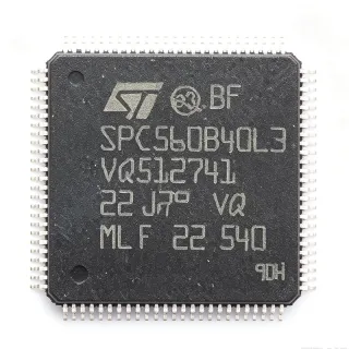
STM32G474VET3 - 170MHz Cortex-M4F MCU 512KB LQFP-100 | ST
MPN: STM32G474VET3 ✓ Hoạt độngSTM32G474VET3 Tóm tắt
An Arm Cortex-M4 microcontroller is a 32-bit RISC processor core designed for deterministic real-time embedded control, with single-precision floating-point, DSP extensions, and a tightly-coupled NVIC for low-latency interrupt handling. Within the broader taxonomy, this part belongs to the MCU -> microcontroller -> semiconductor category, and to ST's STM32G4 series, which adds a CORDIC math accelerator and FMAC filter-math accelerator that offload trigonometric and FIR/IIR computations from the CPU for digital power conversion and motor-control loops.
Key features include five 12-bit ADCs sampling at 4 MSPS with hardware oversampling to 16-bit effective resolution, four 12-bit DAC channels, seven comparators, six op-amps with programmable gain, four 184 ps resolution high-resolution timer channels, USB 2.0 Full-speed with PHY, CAN-FD, three SPI, three I2C, two UART/LPUART, an SDMMC package interface, and a math accelerator block (CORDIC + FMAC). The 100-LQFP exposes 81 GPIO across five voltage-tolerant 5V-tolerant I/O banks.
The STM32G474 architecture pairs the Cortex-M4F core with ST's adaptive real-time ART Accelerator and a multi-bank Flash controller that delivers zero-wait-state execution from Flash at 170 MHz. The integrated op-amps and comparators are tightly coupled to the high-resolution timer to form current-shunt and BEMF sensing loops without external analog ICs, enabling compact, BOM-light field-oriented-control (FOC) motor drives and LLC/PSFB digital power stages.
Typical applications include digital switched-mode power supplies (LLC, PSFB, totem-pole PFC), field-oriented-control motor drives for industrial servos and e-bikes, solar inverters and battery management, USB-C PD controllers, LED lighting controllers, and industrial sensor hubs. The math accelerator is particularly valuable in these loops because CORDIC evaluates sin/cos/atan in as few as 15 cycles.
When designing with this device, place a 100 nF decoupling capacitor on each VDD pin within 2 mm of the package, plus a 4.7 uF bulk cap on the regulator input. Reserve PB8/PB9 for the bootloader or ensure they are not pulled low at reset if you intend to boot from Flash.
This page synthesizes distributor pricing, drop-in alternatives, and practical design notes not found in the manufacturer datasheet. Engineers evaluating the STM32G474VET3 for a 100-LQFP design will find comparison data versus pin-compatible STM32G474xB/xC/xE siblings and GigaDevice GD32G5xx family cross-references here.
Bộ thay thế dễ dàng lắp đặt cho STM32G474VET3 — cùng gói, chân-to-chân tương thích. Các bộ phận yêu cầu hàn PCB bị loại trừ.
Các biến thể trong loạt này
Các mẫu cùng loạt có thể lắp đặt dễ dàng tương thích với STM32G474VET3 (cùng hình factor và footprint) — khác nhau ở Comparators, Core, Operational Amplifiers, Package, Flash Memory.
STM32G474VET6
✅ Drop-InLiên hệ để biết giá
Xem tài liệu →STM32G474VET3TR
✅ Drop-In📋 Tham chiếu thay thế (không có trong danh mục)
STM32G474RET6
✅ Drop-In✓ Còn hàng
$8.25 / Đơn vị
Xem tài liệu →STM32G474CET6
✅ Drop-InLiên hệ để biết giá
Xem tài liệu →STM32G474CET3
✅ Drop-In📋 Tham chiếu thay thế (không có trong danh mục)
STM32G474RBT6
✅ Drop-In✗ Hết hàng
$3.7734 / Đơn vị
Xem tài liệu →STM32G474RBT3
✅ Drop-InLiên hệ để biết giá
Xem tài liệu →STM32G474VET3 Tỷ lệ tối đa & tính chất điện
| Core | Arm Cortex-M4F with FPU and DSP |
| Tần số xung maksimum | 170 MHz |
| CoreMark / DMIPS | 213 DMIPS |
| Flash Memory | 512 KB |
| SRAM | 128 KB |
| Hộp | LQFP-100 (14x14 mm) |
| Operating Voltage | 1.71 V to 3.6 V |
| GPIO Count | 81 |
| ADC | 5x 12-bit, 4 MSPS, HW oversampling to 16-bit |
| DAC | 4x 12-bit |
| Comparators | 7 ultra-fast rail-to-rail |
| Operational Amplifiers | 6 internal op-amps with PGA |
| High-Resolution Timer | 4 channels, 184 ps resolution |
| Math Accelerator | CORDIC + FMAC |
| Communication Interfaces | USB 2.0 FS, CAN-FD, 3x SPI, 3x I2C, 2x UART/LPUART, SDMMC |
| Nhiệt độ hoạt động | -40C to +125C |
| Kiểu lắp đặt | Surface Mount |
| Trạng thái RoHS | Compliant |
Cấu hình chân STM32G474VET3
| Chân 1 | PE2 — GPIO PE2 / TRACECLK |
| Chân 2 | PE3 — GPIO PE3 / TRACED0 |
| Chân 3 | PE4 — GPIO PE4 / TRACED1 |
| Chân 4 | PE5 — GPIO PE5 / TRACED2 |
| Chân 5 | PE6 — GPIO PE6 / TRACED3 |
| Chân 6 | VBAT — RTC backup battery supply |
| Chân 7 | PC13 — GPIO PC13 / TAMPER-RTC |
| Chân 8 | PC14 — GPIO PC14 / OSC32_IN |
| Chân 9 | PC15 — GPIO PC15 / OSC32_OUT |
| Chân 10 | VSS — Ground |
| Chân 11 | VDD — Digital supply voltage |
| Chân 12 | VREF+ — ADC/DAC reference voltage |
| Chân 13 | PA0 — GPIO PA0 / ADC1_INP1 / TIM2_CH1 |
| Chân 14 | PA1 — GPIO PA1 / ADC1_INP2 / TIM2_CH2 |
| Chân 15 | PA2 — GPIO PA2 / USART2_TX / ADC1_INP3 |
| Chân 16 | PA3 — GPIO PA3 / USART2_RX / ADC1_INP4 |
| Chân 17 | PA4 — GPIO PA4 / DAC1_OUT1 / SPI3_NSS |
| Chân 18 | PA5 — GPIO PA5 / DAC1_OUT2 / SPI3_SCK |
| Chân 19 | PA6 — GPIO PA6 / DAC2_OUT1 / SPI3_MISO |
| Chân 20 | PA7 — GPIO PA7 / DAC2_OUT2 / SPI3_MOSI |
| Chân 21 | PC4 — GPIO PC4 / ADC2_INP4 |
| Chân 22 | PC5 — GPIO PC5 / ADC2_INP5 |
| Chân 23 | PB0 — GPIO PB0 / ADC1_INP12 / TIM3_CH3 |
| Chân 24 | PB1 — GPIO PB1 / ADC1_INP11 / TIM3_CH4 |
| Chân 25 | PB2 — GPIO PB2 / BOOT1 |
| Chân 26 | PF11 — GPIO PF11 |
| Chân 27 | PF12 — GPIO PF12 |
| Chân 28 | VSS — Ground |
| Chân 29 | VDD — Digital supply voltage |
| Chân 30 | PE7 — GPIO PE7 |
| Chân 31 | PE8 — GPIO PE8 |
| Chân 32 | PE9 — GPIO PE9 / TIM1_CH1 |
| Chân 33 | PE10 — GPIO PE10 / TIM1_CH2N |
| Chân 34 | PE11 — GPIO PE11 / TIM1_CH2 |
| Chân 35 | PE12 — GPIO PE12 / TIM1_CH3N |
| Chân 36 | PE13 — GPIO PE13 / TIM1_CH3 |
| Chân 37 | PE14 — GPIO PE14 / TIM1_CH4 |
| Chân 38 | PE15 — GPIO PE15 / TIM1_BKIN |
| Chân 39 | PB10 — GPIO PB10 / I2C2_SCL |
| Chân 40 | PB11 — GPIO PB11 / I2C2_SDA |
| Chân 41 | VSS — Ground |
| Chân 42 | VDD — Digital supply voltage |
| Chân 43 | PB12 — GPIO PB12 / SPI2_NSS |
| Chân 44 | PB13 — GPIO PB13 / SPI2_SCK |
| Chân 45 | PB14 — GPIO PB14 / SPI2_MISO |
| Chân 46 | PB15 — GPIO PB15 / SPI2_MOSI |
| Chân 47 | PD8 — GPIO PD8 / USART3_TX |
| Chân 48 | PD9 — GPIO PD9 / USART3_RX |
| Chân 49 | PD10 — GPIO PD10 |
| Chân 50 | PD11 — GPIO PD11 |
| Chân 51 | PD12 — GPIO PD12 |
| Chân 52 | PD13 — GPIO PD13 |
| Chân 53 | PD14 — GPIO PD14 |
| Chân 54 | PD15 — GPIO PD15 / TIM4_CH4 |
| Chân 55 | PC6 — GPIO PC6 / TIM3_CH1 |
| Chân 56 | PC7 — GPIO PC7 / TIM3_CH2 |
| Chân 57 | PC8 — GPIO PC8 / TIM3_CH3 |
| Chân 58 | PC9 — GPIO PC9 / TIM3_CH4 |
| Chân 59 | PA8 — GPIO PA8 / TIM1_CH1 |
| Chân 60 | PA9 — GPIO PA9 / USART1_TX / TIM1_CH2 |
| Chân 61 | PA10 — GPIO PA10 / USART1_RX / TIM1_CH3 |
| Chân 62 | PA11 — GPIO PA11 / USB_DM / CAN1_RX |
| Chân 63 | PA12 — GPIO PA12 / USB_DP / CAN1_TX |
| Chân 64 | PA13 — GPIO PA13 / SWDIO |
| Chân 65 | VSS — Ground |
| Chân 66 | VDD — Digital supply voltage |
| Chân 67 | PA14 — GPIO PA14 / SWCLK |
| Chân 68 | PA15 — GPIO PA15 / JTDI / SPI3_NSS |
| Chân 69 | PC10 — GPIO PC10 / UART4_TX |
| Chân 70 | PC11 — GPIO PC11 / UART4_RX |
| Chân 71 | PC12 — GPIO PC12 / SDMMC_CK |
| Chân 72 | PD0 — GPIO PD0 / CAN1_RX |
| Chân 73 | PD1 — GPIO PD1 / CAN1_TX |
| Chân 74 | PD2 — GPIO PD2 / SDMMC_CMD |
| Chân 75 | PD3 — GPIO PD3 / USART2_CTS |
| Chân 76 | PD4 — GPIO PD4 |
| Chân 77 | PD5 — GPIO PD5 / USART2_RTS |
| Chân 78 | PD6 — GPIO PD6 |
| Chân 79 | PD7 — GPIO PD7 |
| Chân 80 | PB3 — GPIO PB3 / JTDO / TIM2_CH2 |
| Chân 81 | PB4 — GPIO PB4 / NJTRST / TIM3_CH1 |
| Chân 82 | PB5 — GPIO PB5 / TIM3_CH2 |
| Chân 83 | PB6 — GPIO PB6 / USART1_TX / I2C1_SCL |
| Chân 84 | PB7 — GPIO PB7 / USART1_RX / I2C1_SDA |
| Chân 85 | BOOT0 — Boot mode selection |
| Chân 86 | PB8 — GPIO PB8 / TIM4_CH3 |
| Chân 87 | PB9 — GPIO PB9 / TIM4_CH4 |
| Chân 88 | PE0 — GPIO PE0 / TIM4_ETR |
| Chân 89 | PE1 — GPIO PE1 |
| Chân 90 | VSS — Ground |
| Chân 91 | VDD — Digital supply voltage |
| Chân 92 | PF6 — GPIO PF6 / TIM5_CH1 |
| Chân 93 | PF7 — GPIO PF7 / TIM5_CH2 |
| Chân 94 | PF8 — GPIO PF8 / TIM5_CH3 |
| Chân 95 | PF9 — GPIO PF9 / TIM5_CH4 |
| Chân 96 | PF10 — GPIO PF10 |
| Chân 97 | NRST — Reset input (active low) |
| Chân 98 | PA0 — GPIO PA0 / WKUP1 / ADC12_INP0 |
| Chân 99 | VDDA — Analog supply voltage |
| Chân 100 | VSSA — Analog ground |
Ứng dụng tiêu biểu
STM32G474VET3 phù hợp cho 7 Áp dụngs: Digital Switched-Mode Power Supply (LLC/PSFB), Field-Oriented Control Motor Drives, Solar Inverters and Battery Management, USB-C Power Delivery Source/Sink Controllers, Industrial Sensor Hubs and IO-Link Masters, Digital LED Lighting and Stage Controllers, E-Bike and Small EV Motor Controllers.
Digital Switched-Mode Power Supply (LLC/PSFB)
The STM32G474VET3 fits digital LLC and phase-shifted full-bridge (PSFB) power supplies because its Cortex-M4F runs CORDIC math in as few as 15 cycles, enabling 100 kHz+ control loops with FMAC-backed digital filtering. The high-resolution timer delivers 184 ps duty-cycle resolution - critical for valley switching and ZVS detection that boost efficiency above 96 percent in server and EV-charger PSUs. Five 12-bit ADCs at 4 MSPS sample primary current, secondary voltage, and resonant tank signals simultaneously with hardware oversampling, eliminating an external ADC ASIC. Built-in op-amps and comparators handle current-shunt amplification and cycle-by-cycle overcurrent without external analog. The 512 KB Flash holds full DMC and DPFC firmware plus telemetry logs. Compared to a discrete DSP + FPGA solution, this single-chip design cuts BOM by $2 to $4 per board.
Được đề xuất
Field-Oriented Control Motor Drives
The STM32G474VET3 is ideal for industrial servo and BLDC/PMSM motor drives because the integrated CORDIC + FMAC block accelerates Park/Clarke transforms and field-weakening math, while the 184 ps high-resolution timer generates center-aligned PWM with sub-microsecond dead-time insertion. Six on-chip op-amps handle three-phase current sensing without external amplifiers, and seven comparators trip hardware overcurrent in under 50 ns. The 100-LQFP exposes enough GPIO to drive three half-bridges plus encoder, Hall, or resolver feedback. With 213 DMIPS at 170 MHz, this part runs ST's motor-control SDK reference firmware including sensorless FOC at speeds up to 60,000 RPM. The Cortex-M4F FPU ensures smooth torque control under high-dynamic-load conditions typical of robotic joints and CNC axes.
Được đề xuất
Solar Inverters and Battery Management
For photovoltaic string inverters and residential battery management systems, the STM32G474VET3 integrates MPPT calculation, grid-synchronization PLL, and battery-cell monitoring in a single chip. CORDIC accelerates the sin/cos transforms required for SOGI-FLL phase-locked loops used in grid-tie synchronization to IEC 62116 anti-islanding requirements. The 4 MSPS ADCs with hardware oversampling read DC-bus voltage and current with 0.05 percent accuracy, which is essential for 99 percent CEC-weighted inverter efficiency. Five 5V-tolerant I/O banks interface directly to CAN-FD battery stack BMS communication, while the SDMMC package interface logs fault history and energy-yield data to an SD card. USB Full-Speed enables on-site firmware updates and inverter commissioning via ST's commissioning tool.
Được đề xuất
USB-C Power Delivery Source/Sink Controllers
USB-C PD source controllers using the STM32G474VET3 leverage its USB 2.0 Full-speed PHY, 5x fast ADCs for VBUS/VCONN sensing, and 4x DACs that drive analog PWM-controlled buck/boost stages. ST's certified X-CUBE-USB-PD library supports PPS, AVS, and EPR 28V/36V/48V profiles, so a single firmware image handles 100W laptop chargers and 240W EPR sink devices. The CORDIC accelerator computes the cubic polynomials used for programmable supply voltage (PPS) ramp profiles in under 1 microsecond, while the FMAC block provides the digital-loop compensation. The 512 KB Flash accommodates the full USB-PD stack with policy engine, source/sink protocol, and alternate-mode negotiation for DisplayPort and Thunderbolt tunneling.
Được đề xuất
Industrial Sensor Hubs and IO-Link Masters
Industrial sensor hubs and 4-port/8-port IO-Link masters benefit from the STM32G474VET3's 170 MHz compute and 5x 12-bit ADCs with hardware oversampling, which can condition up to 8 analog sensor inputs simultaneously. Three SPI each I/O and three I2C each I/O ports handle the IO-Link COM3 (230.4 kbaud) channels, while the high-resolution timer drives the IO-Link wake-up pulse with sub-microsecond accuracy. Built-in op-amps and comparators implement 4 mA to 20 mA current-loop analog input stages for legacy sensor migration to digital IO-Link masters. The 128 KB SRAM buffers vibration and process data streams for Industry 4.0 edge analytics. CAN-FD uplink aggregates sensor data to the higher-level PLC or industrial Ethernet gateway.
Được đề xuất
Digital LED Lighting and Stage Controllers
High-end architectural and stage LED controllers using the STM32G474VET3 benefit from its 184 ps high-resolution timer to generate smooth 16-bit dim curves that match the human eye's logarithmic brightness perception. Five 12-bit DACs drive up to five independent LED string constant-current regulators via analog control loops. The Cortex-M4F DSP extensions and FMAC accelerator implement real-time CIE 1931 xy color-mixing and gamma-correction math for stage lighting where 16 million colors must transition in under 50 ms. The USB 2.0 Full-speed interface accepts DMX-over-USB input from the keyboard, and CAN-FD connects to inter-rack synchronization busses. The 100-LQFP footprint fits inside 1U rack lighting controllers.
Được đề xuất
E-Bike and Small EV Motor Controllers
Compact e-bike and small-EV motor controllers use the STM32G474VET3 to consolidate torque-control FOC, battery management, and HMI on a single chip. The 6 internal op-amps handle three-phase shunt current sensing without external amplifiers, reducing BOM cost by $1.50 per controller. CORDIC acceleration keeps sensorless FOC loop times under 20 microseconds at 170 MHz, supporting pedal-assist response times under 100 ms as required by EN 15194. The high-resolution timer manages MOSFET dead-time insertion and regenerative braking PWM, while 5V-tolerant GPIO directly interfaces to the throttle, brake, and pedal-torque sensors. CAN-FD uplink connects to the dashboard or fleet telematics unit.
Được đề xuất
Tóm tắt các sản phẩm được đề xuất
Dữ liệu tham khảo kỹ thuật cho STM32G474VET3 — so sánh, hướng dẫn thiết kế và thông tin tuân thủ.
Hướng dẫn chọn lựa
So sánh với các sản phẩm thay thế
| Tham số | Sản phẩm này | STM32G474VET6 | STM32G474VET3TR | STM32G474RET6 | STM32G474CET6 |
|---|---|---|---|---|---|
| Brand | STMicroelectronics | STMicroelectronics | STMicroelectronics | STMicroelectronics | STMicroelectronics |
| Package | LQFP-100 (14x14) | LQFP-100 (14x14) | LQFP-100 (14x14) | LQFP-100 (14x14) | LQFP-100 (14x14) |
| Flash Memory | 512 KB | 512 KB | 512 KB | 512 KB | 256 KB |
| SRAM | 128 KB | 128 KB | 128 KB | 128 KB | 128 KB |
| Core / Frequency | Cortex-M4F / 170 MHz | Cortex-M4F / 170 MHz | Cortex-M4F / 170 MHz | Cortex-M4F / 170 MHz | Cortex-M4F / 170 MHz |
| Operating Temperature | -40C to +125C | -40C to +85C | -40C to +125C | -40C to +85C | -40C to +85C |
| Math Accelerator (CORDIC+FMAC) | Yes | Yes | Yes | Yes | Yes |
Bảo phân biệt quan trọng
- CORDIC + FMAC math accelerator on-chip (vsSTM32F407VET6)
- 184 ps high-resolution timer (vsSTM32G431CBU6)
- Six internal op-amps with PGA (vsGD32G5xx (GigaDevice))
Ghi chú thiết kế
The STM32G474VET3 has 5 VDD/VSS pairs plus dedicated VDDA/VSSA. Place a 100 nF X7R 0402 ceramic decoupling capacitor on each VDD pin within 2 mm of the package, plus a 4.7 uF X5R bulk capacitor shared across the supply rail. The VDDA pin requires a separate low-noise LDO or ferrite-bead filtered 3.3 V, plus a 1 nF + 100 nF decoupling pair to minimize ADC sampling noise. Connect unused VDD pins to the supply and unused VSS pins to ground - never leave them floating - to avoid ESD paths and erratic reset behavior.
Estimated: at full 170 MHz operation driving multiple peripherals, the STM32G474VET3 consumes approximately 90 mW (core + peripherals) from a 3.3 V supply. The LQFP-100 14x14 mm package has theta_JA around 50 C/W on a 4-layer JEDEC PCB, giving a 4.5 C junction rise - well within the 125 C limit. If your design runs at sustained 125 C ambient, derate the clock frequency or add a copper heatsink pad beneath the exposed pad region. Industrial-grade STM32G474VET3 (suffix 3) guarantees operation from -40 C to +125 C.
Keep the high-resolution timer PWM traces (PA8-PA12, PB0-PB1, PE9-PE15) as short as possible and avoid running them parallel to sensitive ADC analog traces (PA0-PA7). Use a 4-layer PCB with a continuous ground plane beneath the LQFP-100 to provide both thermal spreading and a low-impedance return path for high-frequency signals. Place the 32.768 kHz crystal on PC14/PC15 within 5 mm of the pins with a grounded guard ring. The HSE crystal (typically 8 MHz) on PD0/PD1 or PF0/PF1 should also be guarded and supplied by a clean analog-domain supply to reduce PLL jitter.
Do not pull PB8 low at reset - this selects a serial-boot mode that may prevent application code from running. If you boot from Flash and need PB8 for GPIO, ensure the boot pin is in a defined state by reset. The CAN-FD peripheral requires an external transceiver (e.g. TLE9251V) - the STM32G474VET3 has only the protocol controller, not the physical layer. Boot from user Flash by setting BOOT0=0 with a 10 kohm pull-down.
Thông tin tuân thủ
STMicroelectronics STM32G4 series is RoHS compliant per the product page. Not AEC-Q100 qualified - this part targets industrial and consumer applications. For automotive, consider STM32G474VET3-Q1 suffix variant. Lead-free reflow compatible per JEDEC J-STD-020 MSL3.