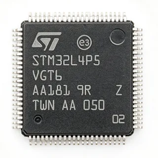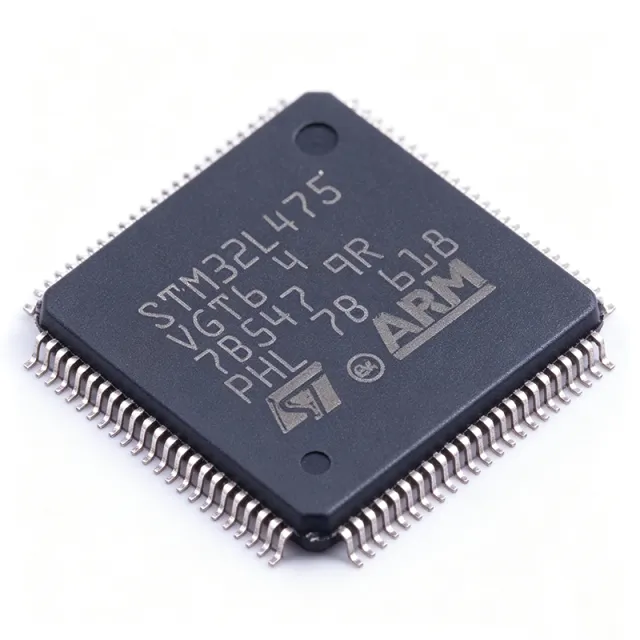
STM32L475VGT6 - 1MB Flash Cortex-M4 MCU, 100-LQFP | STMicroelectronics
MPN: STM32L475VGT6 ✓ نشطSTM32L475VGT6 نظرة عامة
A microcontroller (MCU) is a single-chip integrated circuit containing a processor core, program/data memory, and programmable peripherals that govern a specific embedded function. The STM32L475VGT6 is a member of the STM32L4 ultra-low-power family, which sits within the broader STM32 32-bit MCU portfolio and is engineered around ST's 110 nm ultra-low-leakage process with adaptive real-time (ART) accelerator. The Cortex-M4 core implements the ARMv7-M architecture with single-precision FPU and DSP extensions, making the part a member of the ARM Cortex-M family that is hierarchically classed as an embedded microcontroller -> 32-bit MCU -> semiconductor IC.
Key features include a wide 1.71 V to 3.6 V supply range, batch-collecting 12-bit 5 Msps ADC, two 12-bit DACs, two op-amps, two comparators, USB 2.0 OTG full-speed (with internal PHY), CAN 2.0B, SDMMC, SAI, DFSDM, multiple timers, and a true random number generator (TRNG) for security. Seven main low-power modes (Low-power Run, Sleep, Low-power Sleep, Stop 0/1/2, Standby, Shutdown) bring the typical Stop-mode current down to the microampere range and Standby/Shutdown to the nanoampere range, enabling multi-year battery life when paired with an energy-aware application design.
The architecture combines the Cortex-M4 DSP+FPUs with ST's ART Accelerator (instruction cache + pre-fetch) and an MPU, allowing sustained 100 DMIPS performance while maintaining ultra-low dynamic power. An embedded voltage regulator supports dynamic voltage scaling through the PDR1 (power-down) and LP regulator paths, decoupling core voltage from the external supply.
Typical applications include wearable fitness/health monitors, smart-metering and home/building automation nodes, industrial sensor hubs, medical point-of-care devices, low-power wireless IoT gateways, asset trackers, and USB-powered human-interface peripherals. The integrated USB OTG FS removes the need for an external PHY in many HID/CDC designs.
When designing with the STM32L475VGT6, follow the reference manual's decoupling and layout guidance (one 100 nF per VDD pair, one bulk 4.7 uF on the regulator input) and place the HSE crystal traces within the documented loading and guard-band limits. Selecting the right low-power pair must also consider whether the application can tolerate the wake-up latency of Stop 2 / Standby modes versus the higher autonomy of Low-power Run.
بدائل مباشرة لـ STM32L475VGT6 — نفس الحزمة، متوافق دبوس بدبوس. تُستثنى القطع ذات الحزم المختلفة التي تتطلب تعديل PCB.
الطرازات في هذه السلسلة
طرازات من نفس السلسلة متوافقة تمامًا مع STM32L475VGT6 (نفس عامل الشكل والبصمة) — يختلف في Package, ADC, Core Architecture, DAC, USB.
STM32L476VGT6
✅ بديل مباشرتواصل لمعرفة السعر
عرض ورقة البيانات ←STM32L471ZGT6
✅ بديل مباشرتواصل لمعرفة السعر
عرض ورقة البيانات ←STM32L496RGT6
✅ بديل مباشرتواصل لمعرفة السعر
عرض ورقة البيانات ←GD32F450VGT6
✅ بديل مباشر📋 بديل مرجعي (غير موجود في الكتالوج)
GD32F470VGT6
✅ بديل مباشر📋 بديل مرجعي (غير موجود في الكتالوج)
STM32L475VGT6 الحدود القصوى والخصائص الكهربائية
| Core Architecture | ARM Cortex-M4 with FPU (32-bit) |
| Maximum CPU Clock | 80 MHz |
| Performance | 100 DMIPS |
| Flash Memory | 1 MB (1M x 8) |
| SRAM | 128 KB |
| Supply Voltage Range | 1.71 V to 3.6 V |
| العلبة | 100-LQFP (14x14 mm) |
| درجة حرارة التشغيل | -40 C to +85 C |
| ADC | 3x 12-bit, 5 Msps |
| DAC | 2x 12-bit |
| Comparators | 2x ultra-low-power |
| Op-Amps | 2x on-chip |
| USB | USB 2.0 OTG Full-Speed, integrated PHY |
| CAN | 1x CAN 2.0B |
| Communication Interfaces | I2C, SPI, USART, UART, SAI, SDMMC, DFSDM |
| Timers | 16-bit and 32-bit, multiple channels |
| Security | True Random Number Generator (TRNG), CRC |
| Low-Power Modes | Low-power Run, Stop 0/1/2, Standby, Shutdown |
| حالة RoHS | Compliant |
| نوع التركيب | Surface Mount |
تكوين أطراف STM32L475VGT6
| دبوس 1 | PE2 — GPIO PE2, TRACECLK |
| دبوس 2 | PE3 — GPIO PE3, TRACED0 |
| دبوس 3 | PE4 — GPIO PE4, TRACED1 |
| دبوس 4 | PE5 — GPIO PE5, TRACED2 |
| دبوس 5 | PE6 — GPIO PE6, TRACED3 |
| دبوس 6 | VBAT — Battery backup supply |
| دبوس 7 | PC13 — GPIO PC13, anti-tamper |
| دبوس 8 | PC14 — OSC32_IN (LSE crystal) |
| دبوس 9 | PC15 — OSC32_OUT (LSE crystal) |
| دبوس 10 | VSS — Ground |
| دبوس 11 | VDD — Digital supply 1.71-3.6 V |
| دبوس 12 | PH0 — OSC_IN (HSE crystal) |
| دبوس 13 | PH1 — OSC_OUT (HSE crystal) |
| دبوس 14 | NRST — Active-low reset |
| دبوس 15 | PC0 — GPIO PC0, ADC12_IN1 |
| دبوس 16 | PC1 — GPIO PC1, ADC12_IN2 |
| دبوس 17 | PC2 — GPIO PC2, ADC12_IN3 |
| دبوس 18 | PC3 — GPIO PC3, ADC12_IN4 |
| دبوس 19 | VSSA — Analog ground |
| دبوس 20 | VREF+ — ADC reference voltage |
| دبوس 21 | VDDA — Analog supply 1.71-3.6 V |
| دبوس 22 | PA0 — GPIO PA0, ADC12_IN5, WKUP1 |
| دبوس 23 | PA1 — GPIO PA1, ADC12_IN6 |
| دبوس 24 | PA2 — GPIO PA2, USART2_TX |
| دبوس 25 | PA3 — GPIO PA3, USART2_RX |
| دبوس 26 | VSS — Ground |
| دبوس 27 | VDD — Digital supply 1.71-3.6 V |
| دبوس 28 | PA4 — GPIO PA4, SPI1_NSS, DAC1_OUT1 |
| دبوس 29 | PA5 — GPIO PA5, SPI1_SCK, DAC1_OUT2 |
| دبوس 30 | PA6 — GPIO PA6, SPI1_MISO, ADC12_IN11 |
| دبوس 31 | PA7 — GPIO PA7, SPI1_MOSI, ADC12_IN12 |
| دبوس 32 | PB0 — GPIO PB0, ADC12_IN15 |
| دبوس 33 | PB1 — GPIO PB1, ADC12_IN16 |
| دبوس 34 | PB2 — GPIO PB2, BOOT1 |
| دبوس 35 | VSS — Ground |
| دبوس 36 | VDD — Digital supply 1.71-3.6 V |
| دبوس 37 | PB10 — GPIO PB10, I2C2_SCL, USART3_TX |
| دبوس 38 | PB11 — GPIO PB11, I2C2_SDA, USART3_RX |
| دبوس 39 | PB12 — GPIO PB12, SPI2_NSS |
| دبوس 40 | PB13 — GPIO PB13, SPI2_SCK |
| دبوس 41 | PB14 — GPIO PB14, SPI2_MISO |
| دبوس 42 | PB15 — GPIO PB15, SPI2_MOSI |
| دبوس 43 | PC6 — GPIO PC6, USART6_TX, TIM8_CH1 |
| دبوس 44 | PC7 — GPIO PC7, USART6_RX, TIM8_CH2 |
| دبوس 45 | PC8 — GPIO PC8, SDMMC1_D0, TIM8_CH3 |
| دبوس 46 | PC9 — GPIO PC9, SDMMC1_D1, TIM8_CH4 |
| دبوس 47 | PA8 — GPIO PA8, RCC_MCO_1, USART1_CK |
| دبوس 48 | PA9 — GPIO PA9, USART1_TX |
| دبوس 49 | PA10 — GPIO PA10, USART1_RX |
| دبوس 50 | PA11 — GPIO PA11, USB_DM |
| دبوس 51 | PA12 — GPIO PA12, USB_DP |
| دبوس 52 | PA13 — GPIO PA13, SWDIO |
| دبوس 53 | VSS — Ground |
| دبوس 54 | VDD — Digital supply 1.71-3.6 V |
| دبوس 55 | PA14 — GPIO PA14, SWCLK, JTCK |
| دبوس 56 | PA15 — GPIO PA15, JTDI |
| دبوس 57 | PC10 — GPIO PC10, SDMMC1_D2, USART3_TX |
| دبوس 58 | PC11 — GPIO PC11, SDMMC1_D3, USART3_RX |
| دبوس 59 | PC12 — GPIO PC12, SDMMC1_CK |
| دبوس 60 | PD0 — GPIO PD0, CAN1_RX, FMC_D2 |
| دبوس 61 | PD1 — GPIO PD1, CAN1_TX, FMC_D3 |
| دبوس 62 | PD2 — GPIO PD2, SDMMC1_CMD |
| دبوس 63 | PD3 — GPIO PD3, USART2_CTS |
| دبوس 64 | PD4 — GPIO PD4, USART2_RTS |
| دبوس 65 | PD5 — GPIO PD5, USART2_TX |
| دبوس 66 | PD6 — GPIO PD6, USART2_RX |
| دبوس 67 | PD7 — GPIO PD7, USART2_CK |
| دبوس 68 | PB3 — GPIO PB3, JTDO, SWO, TIM2_CH2 |
| دبوس 69 | PB4 — GPIO PB4, JTRST, TIM3_CH1 |
| دبوس 70 | PB5 — GPIO PB5, I2C1_SMBAI, TIM3_CH2 |
| دبوس 71 | PB6 — GPIO PB6, I2C1_SCL, USART1_TX |
| دبوس 72 | PB7 — GPIO PB7, I2C1_SDA, USART1_RX |
| دبوس 73 | BOOT0 — Boot mode selection |
| دبوس 74 | PB8 — GPIO PB8, I2C1_SCL, CAN1_RX, TIM4_CH3 |
| دبوس 75 | PB9 — GPIO PB9, I2C1_SDA, CAN1_TX, TIM4_CH4 |
| دبوس 76 | VSS — Ground |
| دبوس 77 | VDD — Digital supply 1.71-3.6 V |
| دبوس 78 | PE7 — GPIO PE7, TIM1_ETR |
| دبوس 79 | PE8 — GPIO PE8, TIM1_CH1N |
| دبوس 80 | PE9 — GPIO PE9, TIM1_CH1 |
| دبوس 81 | PE10 — GPIO PE10, TIM1_CH2N |
| دبوس 82 | PE11 — GPIO PE11, TIM1_CH2 |
| دبوس 83 | PE12 — GPIO PE12, TIM1_CH3N |
| دبوس 84 | PE13 — GPIO PE13, TIM1_CH3 |
| دبوس 85 | PE14 — GPIO PE14, TIM1_CH4 |
| دبوس 86 | PE15 — GPIO PE15, TIM1_BKIN |
| دبوس 87 | PA13 — GPIO PA13 (alternate pad location on LQFP-100, see datasheet) |
| دبوس 88 | PC4 — GPIO PC4, USART3_TX |
| دبوس 89 | PC5 — GPIO PC5, USART3_RX |
| دبوس 90 | VSS — Ground |
| دبوس 91 | VDD — Digital supply 1.71-3.6 V |
| دبوس 92 | PB12 — GPIO PB12 (alternate, see datasheet) |
| دبوس 93 | PB13 — GPIO PB13 (alternate, see datasheet) |
| دبوس 94 | PB14 — GPIO PB14 (alternate, see datasheet) |
| دبوس 95 | PB15 — GPIO PB15 (alternate, see datasheet) |
| دبوس 96 | PA8 — GPIO PA8 (alternate, see datasheet) |
| دبوس 97 | PA9 — GPIO PA9 (alternate, see datasheet) |
| دبوس 98 | PA10 — GPIO PA10 (alternate, see datasheet) |
| دبوس 99 | PA11 — GPIO PA11 (alternate, see datasheet) |
| دبوس 100 | PA12 — GPIO PA12 (alternate, see datasheet) |
التطبيقات النموذجية
STM32L475VGT6 مناسب لـ 6 التطبيقs: Wearable Health & Fitness Monitor, Smart Metering & Energy Harvesting Node, Industrial Sensor Hub with USB-C, Medical Point-of-Care Device, Low-Power IoT Gateway / Asset Tracker, Battery-Powered HMI / Keyboard.
Wearable Health & Fitness Monitor
The STM32L475VGT6 fits wearable health-and-fitness monitors because its Cortex-M4F DSP+FPU accelerates heart-rate, SpO2, and motion-sensor DSP pipelines while its ultra-low-power modes extend battery life. Stop 2 mode draws microampere-range quiescent current, allowing multi-week runtimes on a small Li-Po battery. The 12-bit 5 Msps ADC pairs with on-chip op-amps to condition bioimpedance and PPG signals without external analog front-ends. USB OTG FS with integrated PHY simplifies charging/CDC data synchronization with no external ULPI device. Recommended peripherals: STMicroelectronics LIS2DS12 accelerometer for motion context, STM32L476 companion for upgrade paths.
موصى به
Smart Metering & Energy Harvesting Node
The STM32L475VGT6 fits smart-metering and energy-harvesting nodes because its 1.71-3.6 V supply range accepts direct output from small solar/PEM cells and its nanoampere Standby/Shutdown modes preserve battery during long idle windows. The Cortex-M4F runs metering DSP (RMS, harmonic analysis) at 80 MHz with 100 DMIPS headroom, and the SDMMC plus DFSDM peripherals interface to external metrology ASICs. Recommended companions: STMicroelectronics STPMIC1 power management IC, STM32L496RGT6 upgrade option with more SRAM.
موصى به
Industrial Sensor Hub with USB-C
The STM32L475VGT6 fits industrial sensor hubs because its CAN 2.0B interface plus USB OTG FS provide both industrial bus connectivity and a USB-C host/device port for local HMI. Three 12-bit 5 Msps ADCs and two on-chip op-amps support multi-sensor analog front-ends without external amplifiers. The wide 1.71-3.6 V supply simplifies 24 V industrial-rail step-down to a single 3.3 V rail. Recommended companions: STMicroelectronics STM32F105RCT6 CAN bridge, STM32L073RZ for cost-down sensor-node designs.
موصى به
Medical Point-of-Care Device
The STM32L475VGT6 fits medical point-of-care devices because its Cortex-M4F with FPU executes DSP-heavy signal-processing for ECG, pulse-oximetry, and impedance measurement in real time. The two 12-bit DACs and two on-chip op-amps condition analog front-end signals, while the SAI peripheral drives audio prompts or MEMS microphones. The TRNG provides the entropy source needed for authenticated firmware updates on medical hardware. Recommended companions: STMicroelectronics STM32H735IIT6 high-performance option, STM32L4R9ZIT6 for designs needing external SDRAM.
موصى به
Low-Power IoT Gateway / Asset Tracker
The STM32L475VGT6 fits low-power IoT gateways and asset trackers because its USB OTG FS plus CAN, SDMMC, and SAI allow multiple wireless modules (LoRa, BLE, sub-GHz) to be hosted on a single MCU. Stop 2 mode draws microampere-level quiescent current when no events are pending, and the wide 1.71-3.6 V input tolerates battery droop during cold-temperature transients. Recommended companions: STMicroelectronics STM32MP135DAC3 for Linux-capable gateways, STM32F103VBT6 cost-down auxiliary.
موصى به
Battery-Powered HMI / Keyboard
The STM32L475VGT6 fits battery-powered human-interface devices such as wireless keyboards, game controllers, and presenters because its low-power modes plus USB OTG FS (with integrated PHY) support both wireless 2.4 GHz dongles and USB-C wired modes. The 80 MHz Cortex-M4F runs HID report parsing and LED-matrix drivers in real time without external logic. Recommended companions: STMicroelectronics STM32G071G8U6 for ultra-low-cost wired-only HMI, STM32L051C8T3 for cost-sensitive button-only designs.
موصى به
ملخص المنتجات الموصى بها
بيانات مرجعية هندسية لـ STM32L475VGT6 — المقارنة وإرشادات التصميم ومعلومات الامتثال.
دليل الاختيار
المقارنة مع البدائل
| المعامل | هذا المنتج | STM32L476VGT6 | STM32L471ZGT6 | GD32F450VGT6 | GD32F470VGT6 |
|---|---|---|---|---|---|
| Brand | STMicroelectronics | STMicroelectronics | STMicroelectronics | GigaDevice | GigaDevice |
| Package | 100-LQFP (14x14 mm) | 100-LQFP (14x14 mm) - same | 100-LQFP (14x14 mm) - same | 100-LQFP (14x14 mm) - same | 100-LQFP (14x14 mm) - same |
| Core | ARM Cortex-M4F @ 80 MHz | ARM Cortex-M4F @ 80 MHz | ARM Cortex-M4F @ 80 MHz | ARM Cortex-M4F @ 200 MHz | ARM Cortex-M4F @ 240 MHz |
| Flash | 1 MB | 1 MB | 1 MB | 1 MB | 1 MB |
| SRAM | 128 KB | 128 KB | 128 KB | 256 KB | 256 KB |
| USB OTG | Yes (FS, integrated PHY) | Yes (FS, integrated PHY) | Yes (FS, integrated PHY) | Yes (FS, integrated PHY) | Yes (FS/HS) |
| Hardware Crypto | TRNG + CRC | AES-256 + TRNG | TRNG + CRC | AES + TRNG | AES + TRNG |
| Stop Mode Current | Low (ultra-low-power family) | Low | Low | Higher than STM32L4 | Higher than STM32L4 |
| Supply Voltage Range | 1.71 V to 3.6 V | 1.71 V to 3.6 V | 1.71 V to 3.6 V | 2.6 V to 3.6 V | 2.6 V to 3.6 V |
| Unit Price (qty 1000) | $5.85 | Slightly higher than L475 | Comparable to L475 | Lower (cost-down option) | Lower (cost-down option) |
أبرز الفروقات
- Cortex-M4F with FPU at 80 MHz with 100 DMIPS and 7-mode ultra-low-power architecture (مقابلSTM32F103VBT6)
- Integrated USB OTG Full-Speed PHY (no external ULPI device required) (مقابلGD32F450VGT6)
- AES-256 upgrade path in the same LQFP-100 footprint (مقابلSTM32L476VGT6)
ملاحظات التصميم
Place one 100 nF decoupling capacitor as close as possible to each VDD pin and one bulk 4.7 uF ceramic at the regulator input (VDD/VDDA pair). According to the STM32L475xx datasheet power-supply section, using shared decoupling for the VDD/VDDA pins can couple digital switching transients into the analog reference and degrade ADC SNR by 4-6 dB. Use separate ferrite-bead-isolated rails for VDDA in metering and audio designs.
Route the HSE crystal traces within 7 mm of OSC_IN/OSC_OUT and keep the loading capacitors within the datasheet-specified CL range (typically 6-10 pF on STM32L4). Maintain a ground guard ring around the crystal and avoid routing signal traces under or near it; violating these rules typically causes HSE crystal-startup failures or 0.5-1% frequency error at temperature. Estimated crystal trace parasitic of 5 pF should be subtracted from the load-capacitor budget.
When migrating Stop 2 to Stop 0 for faster wake-up latency, the SDMMC, SAI, and DFSDM peripherals lose their configuration state and must be reinitialized in the wake-up ISR. Estimated wake-up time from Stop 2 is around 5-10 us vs 1 us from Stop 0; choose Stop 0 only when the application cannot tolerate the longer wake-up latency. Also note: Shutdown mode removes RTC backup register retention unless VBAT is held.
At 80 MHz active and 1.71-3.6 V supply, typical active current is approximately 10 mA / MHz giving 800 mW maximum at full CPU load on the 100-LQFP. The LQFP-100 has theta_JA around 50 C/W on a 4-layer JEDEC test board, so a 800 mW full-load dissipation yields about 40 C junction temperature rise above ambient; no heatsink is required for typical IoT workloads. Verify thermal rise at ambient 85 C to confirm Tjunction stays below 110 C.
معلومات الامتثال
RoHS and REACH compliant per ST product page. Standard grade is not AEC-Q100 qualified; choose AEC-Q100 qualified automotive variants (STM32L475RG-A) for automotive applications.