Transistors
Products (6)
ADUM3223ARWZ - 4A Isolated Half-Bridge Gate Driver | Analog Devices
The ADUM3223ARWZ is a 4 A isolated, half-bridge gate driver from Analog Devices, employing iCoupler technology to provide independent and isolated high-side and low-side outputs. It offers 3000 V rms isolation in a narrow body, 16-lead SOIC package, making it suitable for a wide range of power conversion applications. The device combines high speed CMOS and monolithic transformer technology, delivering robust performance with minimal propagation delay and excellent common-mode transient immunity. An isolated gate driver is a specialized integrated circuit that provides the necessary voltage and current to drive the gate of power transistors (such as MOSFETs and IGBTs) while maintaining galvanic isolation between the control side and the power stage. This isolation is critical in applications where the power stage operates at high voltages or in noisy environments, protecting the low-voltage control circuitry and ensuring safe, reliable operation. Isolated gate drivers are essential components in switch-mode power supplies, motor drives, and inverters, where they enable efficient and safe switching of high-power devices. Key features of the ADUM3223ARWZ include 4 A peak output current, 3000 V rms isolation, and a wide supply voltage range. The device supports both high-side and low-side outputs with independent inputs, allowing flexible control of half-bridge topologies. It also features a high common-mode transient immunity (CMTI) of typically 100 kV/us, ensuring reliable operation in noisy environments. The propagation delay is typically 50 ns, enabling high-frequency switching with minimal timing skew. Technically, the ADUM3223ARWZ integrates Analog Devices' iCoupler technology, which uses chip-scale transformers to transmit signals across the isolation barrier. This approach offers advantages over traditional optocouplers, including higher speed, lower power consumption, and better reliability. The device is designed to drive power MOSFETs and IGBTs directly, with a wide output supply range from 4.5 V to 18 V, accommodating various gate drive requirements. The narrow body SOIC-16 package is compact and suitable for space-constrained designs. Typical applications include isolated switch-mode power supplies, motor drives, solar inverters, and industrial automation. The ADUM3223ARWZ is particularly well-suited for half-bridge and full-bridge topologies where high-side and low-side drivers are required. Its high output current ensures fast switching of large gate capacitances, reducing switching losses and improving efficiency. When designing with this device, it is important to provide adequate decoupling on both the input and output supplies, and to ensure proper layout to minimize parasitic inductance. The device also requires careful consideration of the isolation rating and creepage distances for the target application's safety standards.

BU931T - 15A, 400V NPN Power Darlington Transistor | STMicroelectronics
The BU931T is an NPN power Darlington transistor manufactured by STMicroelectronics, designed for high-current switching applications. It features a collector-emitter voltage (VCEO) of 400V, a continuous collector current (IC) of 15A, and a peak collector current of 30A. The device is housed in a TO-220 package, providing excellent thermal performance for power dissipation up to 125W. With a DC current gain (hFE) of 500 minimum at 10A, it offers high current amplification, making it suitable for motor control, power supplies, and automotive ignition systems. A Darlington transistor is a compound structure consisting of two bipolar junction transistors (BJTs) connected in a Darlington pair configuration, where the emitter of the first transistor drives the base of the second. This configuration provides extremely high current gain, typically in the range of 1000 to 10000, compared to a single BJT. Darlington transistors are widely used in high-current switching applications where a low base current is required to control a large collector current. They are part of the broader family of power transistors, which also includes MOSFETs and IGBTs, and are essential components in power electronics for amplification and switching. Key features of the BU931T include a collector-emitter saturation voltage (VCE(sat)) of 2.0V maximum at IC=10A, ensuring low power loss during conduction. The device also offers a fast switching speed with a fall time of 1.5 microseconds, making it suitable for high-frequency applications up to 10 kHz. The integrated base-emitter resistor and base-emitter diode enhance reliability by preventing spurious turn-on due to leakage currents. The TO-220 package is lead-free and RoHS compliant, meeting modern environmental standards. Technically, the BU931T utilizes a triple-diffused planar process, providing robust avalanche energy handling and a wide safe operating area (SOA). The device can withstand a collector-emitter breakdown voltage (BVCEO) of 400V and a collector-base voltage (VCBO) of 500V, ensuring high voltage robustness. The thermal resistance from junction to case (RthJC) is 1.0°C/W, allowing efficient heat transfer to an external heatsink. The operating junction temperature range is -65°C to +150°C, making it suitable for harsh environments. Typical applications include motor control circuits, switching power supplies, automotive ignition systems, and solenoid drivers. In motor control, the BU931T can switch DC motors up to 15A, providing reliable on/off control. In automotive ignition, its high voltage and current ratings ensure dependable performance in demanding conditions. The device is also used in welding equipment and battery chargers where high current switching is required. When designing with the BU931T, ensure adequate base drive current to achieve low saturation voltage. A base current of at least 1/250 of the collector current is recommended. Additionally, use a suitable heatsink to maintain junction temperature below 150°C, especially at high current levels. Proper snubber circuits may be required to protect against inductive load transients.
BU941ZT - 15A, 350V NPN Power Transistor | STMicroelectronics
The STMicroelectronics BU941ZT is a high-voltage, high-current NPN power transistor designed for demanding switching and linear applications. It delivers a continuous collector current of 15A and supports a collector-emitter voltage of 350V, making it suitable for power management, motor control, and industrial systems. The device is housed in a TO-220 package, which provides excellent thermal performance and is widely used in through-hole PCB designs. A power transistor is a three-terminal semiconductor device used to amplify or switch electronic signals and electrical power. In the hierarchy of power electronics, the BU941ZT is a bipolar junction transistor (BJT), which falls under the category of discrete semiconductors, specifically power transistors. BJTs are current-controlled devices where a small base current controls a larger collector current, enabling efficient power regulation and switching in circuits such as power supplies, inverters, and motor drivers. Key features of the BU941ZT include a high collector-emitter voltage rating of 350V, a continuous collector current of 15A, and a low saturation voltage that minimizes power loss during conduction. The device also offers a high DC current gain (hFE) for efficient base drive, and a fast switching speed suitable for applications up to several kilohertz. The TO-220 package includes a metal tab for heatsinking, allowing the transistor to dissipate significant power when properly mounted. Technically, the BU941ZT is fabricated using STMicroelectronics' advanced bipolar process, which ensures high ruggedness and reliability under stressful operating conditions. The device features a wide safe operating area (SOA) and built-in protection against overcurrent and overtemperature, making it robust for industrial environments. Its low saturation voltage (VCE(sat)) of typically 1.5V at 15A reduces conduction losses, improving overall system efficiency. Typical applications include switch-mode power supplies (SMPS), motor control circuits, inverters, and battery chargers. In an SMPS, the BU941ZT can be used as the main switching element, handling high voltages and currents while maintaining low losses. In motor control, it drives inductive loads with fast switching and high current capability. The device is also suitable for linear regulators and audio amplifiers where high power handling is required. When designing with the BU941ZT, ensure adequate base drive current to fully saturate the transistor and minimize power dissipation. Use a proper heatsink or thermal pad to manage the heat generated during operation, especially at high currents. Additionally, consider adding a flyback diode across inductive loads to protect the transistor from voltage spikes during switching.
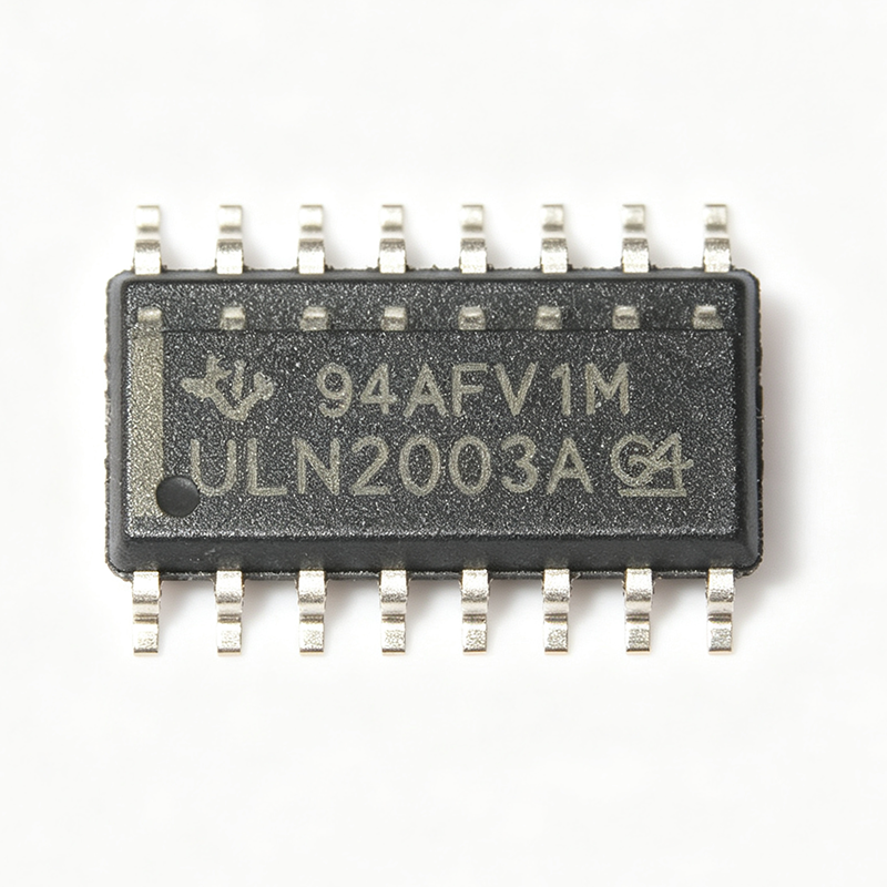
ULN2003AD - 7-Channel Darlington Driver | Texas Instruments
The Texas Instruments ULN2003AD is a 7-channel high-voltage, high-current Darlington transistor array designed for driving inductive loads such as relays, solenoids, stepper motors, and lamps. It features seven open-collector Darlington pairs with common-cathode clamp diodes for inductive transient suppression, and is available in a 16-pin SOIC (D) package. Each channel can sink up to 500 mA continuously and 600 mA peak, with a collector-emitter voltage rating of 50 V. The device operates over a temperature range of -40°C to +105°C and is RoHS compliant. A Darlington transistor array is a semiconductor device that integrates multiple Darlington pairs, each consisting of two bipolar transistors in a configuration that provides high current gain. This category falls under the hierarchy: Darlington array -> transistor array -> discrete semiconductor -> semiconductor. The ULN2003A is a specific variant of the ULN2003 family, which is widely used in industrial and consumer applications for interfacing low-level logic signals to high-current loads. Key features include seven Darlington pairs with a total current capability of 500 mA per channel, a collector-emitter voltage rating of 50 V, and integrated clamp diodes for inductive load protection. The input is compatible with TTL and 5V CMOS logic, and the device includes a common emitter for all channels. The SOIC-16 package provides a compact footprint for space-constrained designs. The ULN2003AD uses a bipolar process technology with a high-current NPN Darlington configuration. Each channel has a base resistor (2.7 kΩ) and an emitter resistor (3.6 kΩ) to ensure proper biasing and thermal stability. The integrated clamp diodes are connected to a common cathode pin (pin 9) for easy connection to the supply rail. The device exhibits a low saturation voltage (typically 1.6 V at 350 mA) to minimize power dissipation. Typical applications include relay drivers, stepper motor drivers, solenoid drivers, and lamp drivers in industrial control, automotive, and consumer electronics. The high current gain allows direct interfacing with microcontrollers without additional driver stages, simplifying circuit design. When designing with this device, ensure that the total power dissipation does not exceed the package thermal limits. For high-current applications, consider using multiple channels in parallel or adding external heatsinking. The clamp diodes must be connected to the positive supply rail to protect against inductive kickback. This page synthesizes distributor pricing, drop-in alternatives, and practical design notes not found in the TI datasheet, providing a comprehensive resource for engineers selecting the ULN2003AD.

ULN2803ADWR - 8ch 50V 500mA Darlington Array | Texas Instruments
The Texas Instruments ULN2803ADWR is a high-voltage, high-current Darlington transistor array containing eight NPN Darlington pairs in an 18-pin SOIC (DW) surface-mount package. Each channel is rated for 50V collector-emitter voltage and 500mA collector current, with integral common-cathode clamp diodes for switching inductive loads. A Darlington transistor array is an integrated circuit that combines multiple Darlington pairs - two bipolar transistors cascaded for very high current gain - into a single device. This allows low-current logic outputs from microcontrollers or TTL/CMOS logic to switch high-current loads such as relays, solenoids, and stepper motor windings. The ULN2803A belongs to the power switch IC family, under the broader transistor array and load driver category within power management semiconductors. Key features include TTL and 5V CMOS compatible inputs with built-in series base resistors, a 2.7k ohm input resistance per channel, common-emitter configuration with an exposed COM pin (pin 10) connecting the clamp diode cathodes to the load supply for back-EMF suppression. Channels can be paralleled for higher current. Operating temperature is -40C to +85C (A-grade), suited to industrial environments. Internally, each of the eight NPN Darlington pairs includes base and emitter resistors ensuring consistent turn-on thresholds, and each output pairs with a freewheeling clamp diode tied to COM. Total package power dissipation is limited by thermal capability, typically around 1.4W at 25C ambient with adequate PCB copper. Saturation voltage is approximately 1V at moderate currents, a characteristic trade-off of Darlington output stages. Typical applications include relay drivers, hammer and lamp drivers, solenoid drivers, stepper motor drivers (commonly paired with bipolar stepper motors in 3D printers and CNC machines), LED display drivers, and logic buffers. It directly interfaces 3.3V/5V microcontroller GPIO or 5V logic to high-current loads in a single SOIC-18 footprint. Design tip: always connect the COM pin (pin 10) to the load positive supply to enable the clamp diodes; otherwise inductive kickback will destroy the outputs. Budget total dissipation across all channels and provide copper pour for heat spreading. Note this device is in Last Time Buy status - see alternatives below. This page synthesizes distributor pricing, drop-in alternatives, and practical design notes not found in the manufacturer datasheet, helping engineers migrate from this EOL part with minimal PCB rework.
VIPERGAN65 - 650V GaN Power Transistor | STMicroelectronics
The STMicroelectronics VIPERGAN65 is a 650V enhancement-mode Gallium Nitride (GaN) power transistor designed for high-efficiency power conversion applications. It integrates a GaN power HEMT with a gate driver and protection features in a compact PQFN 8x8 mm package, enabling high-frequency operation and reduced system size. What is a GaN power transistor? A Gallium Nitride (GaN) power transistor is a wide-bandgap semiconductor device that switches faster and more efficiently than traditional silicon MOSFETs. It belongs to the power transistor family, which includes MOSFETs, IGBTs, and bipolar transistors. GaN devices offer lower on-resistance and lower gate charge, making them ideal for high-frequency power converters such as AC-DC adapters, server power supplies, and wireless charging systems. Key features of the VIPERGAN65 include a 650V drain-source voltage rating, low on-resistance (RDS(on)) of [DATA_NEEDED: RDS(on)], and a gate driver with integrated protection. The device supports high switching frequencies up to [DATA_NEEDED: max switching frequency] MHz, reducing the size of magnetic components. It also features overcurrent, overtemperature, and undervoltage lockout protection, enhancing system reliability. Technically, the VIPERGAN65 uses a cascode configuration with a GaN HEMT and a silicon MOSFET, simplifying gate drive requirements. The integrated driver eliminates external gate driver components, reducing board space and design complexity. The device's fast switching transitions minimize switching losses, improving overall efficiency in power conversion. Typical applications include AC-DC adapters for laptops and smartphones, server power supplies, and LED lighting drivers. The high efficiency and small form factor make it suitable for space-constrained designs. In a 65W USB-PD adapter, the VIPERGAN65 can achieve over 93% efficiency, reducing heat dissipation and enabling compact enclosures. When designing with the VIPERGAN65, ensure proper PCB layout with short, low-inductance paths for the gate drive and power loops. Use a dedicated ground plane and place decoupling capacitors close to the device. Thermal management is critical; use a thermal pad and adequate copper area to dissipate heat from the package.