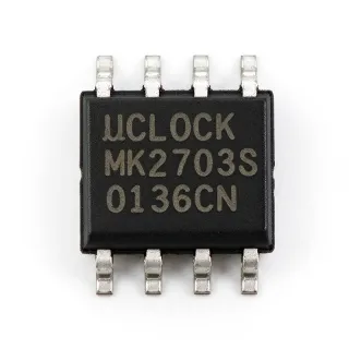
ICS511MIT - 160MHz PLL Clock Multiplier | Renesas | 8-SOIC
N.º de pieza: ICS511MIT ✗ Fin de vidaICS511MIT Descripción general
A PLL clock multiplier belongs to the clock and timing IC family. Unlike a simple logic inverter or buffer, it uses a phase-locked loop to lock an internal or output frequency to a stable reference and multiply that reference by an integer ratio. Clock generators and frequency synthesizers sit within the broader timing-control hierarchy used to coordinate processors, transceivers, memory, and data-conversion equipment.
The primary identified characteristics are a 160 MHz maximum clock frequency, a PLL clock-multiplier function, and an 8-SOIC package measuring 0.154 inch, or 3.90 mm, in body width. The ICS511MIT is also described as a high-frequency clock generator intended for precision applications. Its supported input sources are identified as a clock or crystal, and it belongs to the ICS511 series.
Because the device is obsolete, lifecycle planning is more important than headline performance differences. An existing design can often continue using the same ICS511 family pin arrangement, but a clock source is a board-level dependency: replacement parts must reproduce the reference frequency, output frequency range, output drive, and pin mapping. A nominal maximum frequency alone does not guarantee timing compatibility with an existing circuit.
Typical uses include precision frequency multiplication in communications equipment, clock distribution for high-speed digital subsystems, test and measurement instrumentation, and timing architectures that require a derived clock rather than a free-running oscillator. In such systems, the PLL output replaces or supplements a lower-frequency reference while preserving phase coherence with the reference source.
When laying out a board, route the reference input and clock outputs away from noisy switching nodes and provide a stable ground reference beneath the device. Keep clock traces short, use controlled-impedance routing when operating at high edge rates, and confirm the exact output-divider and feedback configuration against the manufacturer datasheet before releasing a new layout.
This page combines the identified device characteristics, lifecycle information, cross-reference results, and practical clock-tree guidance. It also documents the limitations of an obsolete timing IC so procurement and engineering teams can assess redesign risk rather than relying on a headline frequency rating alone.
Alternativas directas para ICS511MIT — mismo encapsulado, compatible pin a pin. Se excluyen las piezas de otro encapsulado que requieren retrabajo de la PCB.
Variantes de esta serie
Modelos de la misma serie compatibles directamente con ICS511MIT (mismo factor de forma y huella) — difiere en Package, Product Type, Manufacturer, Series.
ICS511M
✅ Sustitución directaConsulte el precio
Ver hoja de datos →ICS511MT
✅ Sustitución directaConsulte el precio
Ver hoja de datos →ICS511MI
✅ Sustitución directaConsulte el precio
Ver hoja de datos →ICS511ML
✅ Sustitución directa ⚠️ Especificaciones sin verificar📋 Alternativa de referencia (no en el catálogo)
ICS511MIT Especificaciones
| Product Type | PLL clock multiplier / clock generator IC |
| Manufacturer | Renesas Electronics |
| Series | ICS511 |
| Frecuencia de reloj máxima | 160 MHz |
| Multiplier Output | 1 |
| Reference Input | Clock or crystal |
| PLL | Yes |
| Encapsulado | 8-SOIC |
| Package Body Width | 0.154 inch (3.90 mm) |
| Tipo de montaje | Surface mount |
| Shipping Format | Tape and reel |
| Product Status | Obsolete |
| Programmability | Not verified |
Guía de configuración de pines de ICS511MIT 0.154 inch (3.90 mm)
Configuración de pines para ICS511MIT (encapsulado 0.154 inch (3.90 mm)). La numeración de pines, las funciones y los diagramas de conexión se definen en la hoja de datos del fabricante. Consúltela para conocer el footprint exacto y las directrices de soldadura.

No hay datos detallados de patillaje disponibles para ICS511MIT.
Consulte la hoja de datos para ver la configuración completa de patillas.
Aplicaciones típicas
ICS511MIT es adecuado para 6 aplicacións: Precision Communications Clocking, High-Speed Digital Subsystem Clocking, Test and Measurement Instrumentation, Industrial Control and Data Acquisition, Phase-Coherent Clock Distribution, Legacy System Maintenance and Repair.
Precision Communications Clocking
The ICS511MIT is suitable for a communications subsystem that needs a higher-frequency, phase-coherent clock derived from a lower-frequency reference. Its PLL clock-multiplier architecture and listed 160 MHz maximum frequency make it appropriate for serializer, transceiver, or high-speed digital interface timing. Place the reference source close to the device, keep the feedback and output routes short, and confirm that the required multiplication ratio and output frequency fall within the part-specific limits in the datasheet. Because the ICS511MIT is obsolete, it is most appropriate for maintaining an existing qualified design rather than driving a new platform.
Recomendado
High-Speed Digital Subsystem Clocking
Use the ICS511MIT to create a multiplied clock for logic that requires more clock frequency than the board reference can supply directly. The identified 160 MHz capability supports high-speed clock-tree sections in processor, storage, and data-conversion systems, provided the actual output range and output-drive requirements are verified from the manufacturer datasheet. Route the clock as a transmission-line class net if rise time demands it, avoid unnecessary stubs, and keep switching regulators and high-current nets physically separated from the reference and clock outputs.
Recomendado
Test and Measurement Instrumentation
The ICS511MIT can supply a derived clock for instrumentation requiring a stable reference relationship across multiple internal circuits. Using a PLL multiplier allows a single crystal-derived reference to support other clock domains while maintaining a defined relationship to the source. The design must account for reference purity, output jitter, and the propagation delay through the feedback loop. Validate the maximum frequency and reference-input conditions in the datasheet, and measure the generated clock at the load rather than relying only on an unloaded probe point.
Recomendado
Industrial Control and Data Acquisition
The ICS511MIT can support industrial control and data-acquisition boards that synchronize sampling, conversion, and processing sections to a common reference. Its listed clock-generator function, PLL capability, and 160 MHz maximum frequency suit systems requiring deterministic timing relationships between modules. Keep analog and power-conversion sections separated from the clock generator, maintain a low-impedance ground return, and verify the operating-temperature grade before using the part in industrial equipment. For new platforms, evaluate the current supported alternative alongside the legacy ICS511 family.
Recomendado
Phase-Coherent Clock Distribution
Use the ICS511MIT when several logic domains must remain phase-coherent rather than simply receive independent oscillator outputs. A PLL-multiplied clock provides a derived frequency with a defined relationship to its clock or crystal reference, which is useful for parallel data paths, converters, and timing controllers. The reference trace should be short and isolated, while clock outputs should be buffered or routed according to the load capacitance specified by the manufacturer. Scope the waveform at the far end of the board to verify amplitude, edge quality, and absence of reflected pulses.
Recomendado
Legacy System Maintenance and Repair
The ICS511MIT is most relevant to maintenance, repair, and lifecycle-extension programs for equipment that already uses the ICS511 family. Its 8-SOIC package and identified 160 MHz clock-generator specification support controlled substitution within an existing design, provided the reference-input range, pin mapping, supply requirements, and temperature grade are confirmed. Document any alternate ordering code in the equipment records and perform timing measurements after replacement. New production quantities should be reserved for spares rather than assumed as a guaranteed long-term supply.
Recomendado
Resumen de productos recomendados
Datos de referencia de ingeniería para ICS511MIT — comparación, orientación de diseño e información de cumplimiento.
Guía de selección
Comparación con alternativas
| Parámetro | Este producto | ICS511M | ICS511MT | ICS511MI | ICS511ML |
|---|---|---|---|---|---|
| Package | 8-SOIC | 8-SOIC | 8-SOIC | 8-SOIC | 8-SOIC |
| Brand | Renesas Electronics | Renesas Electronics | Renesas Electronics | Renesas Electronics | Renesas Electronics |
Diferenciadores clave
- Documented high-frequency ICS511 clock-generator positioning (frente a ICS511M)
- Same-family alternative with matching tape-and-reel logistics (frente a ICS511MI)
- Direct ordering-code continuity within the ICS511 family (frente a ICS511MT)
Notas de diseño
Treat the reference input and clock outputs as high-speed signals even when the reference frequency is relatively low. Place the ICS511MIT close to the oscillator or crystal network, keep the reference path short, and avoid routing it beneath digital return currents. Place any crystal at the device pins and keep unrelated high-current switching nodes away from the oscillator area to reduce supply-to-output coupling and clock jitter.
Confirm output amplitude, edge rate, and load capability at the far end of the clock route. If the trace length or edge rate creates a transmission-line condition, use a controlled-impedance layout with a defined termination strategy instead of relying on a point probe at the generator. Avoid long stubs and test taps that add capacitive loading, because either effect can degrade rise time and shift the timing relationship seen by downstream logic.
Do not treat every ICS511 ordering code as electrically identical. Verify the exact pinout, supply voltage, reference-frequency range, output-frequency limit, temperature grade, and feedback configuration before replacing the ICS511MIT. A package match and a 160 MHz class headline value do not prove timing compatibility. For production maintenance, record the approved alternate part number and validate it against the original schematic and operating envelope.
Follow the manufacturer bypass-capacitor recommendations and provide the required supply decoupling directly at the device pins. A clock generator can translate supply noise directly into output jitter, especially when the PLL multiplies a reference containing periodic disturbances. Route the return current through an uninterrupted ground plane, keep the decoupling loop compact, and verify supply ripple at the IC rather than only at the power supply connector.
Información de cumplimiento
The indexed product information identifies the device as obsolete but does not state RoHS, REACH, AEC-Q100, lead-free, halogen-free, or conflict-minerals status. Compliance attributes therefore remain unknown.