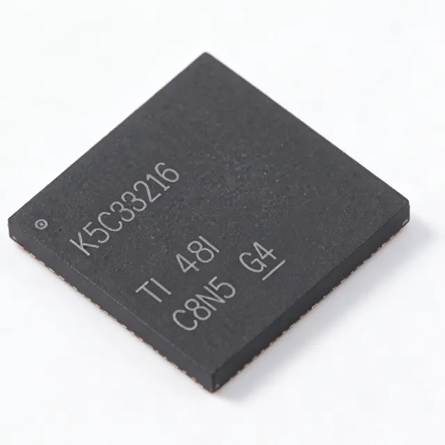
LMK5C33216RGCR - Ultra-Low Jitter Clock Synchronizer | TI
Référence : LMK5C33216RGCR ✓ Actif| Qté | Prix unitaire | Total |
|---|---|---|
| 1 | $52.07 | $52,07 |
| 10 | $48.5 | $485,00 |
| 100 | $42 | $4 200,00 |
| 500 | $38 | $19 000,00 |
| 1 000 | $35 | $35 000,00 |
LMK5C33216RGCR Présentation
A clock synchronizer is a specialized timing IC that generates and aligns multiple clock signals to a reference, often cleaning jitter from noisy sources. In the hierarchy of timing components, a clock synchronizer sits above a simple PLL or clock generator, providing advanced features like hitless switching, holdover, and digital loop filtering. The LMK5C33216 is part of TI's LMK5C family, which targets 5G base stations, small cells, and other high-speed networking equipment where precise timing is critical for JESD204B data converters.
Key features include three DPLLs with programmable loop bandwidth from 0.01 Hz to 4 kHz, eliminating the need for external loop filters. The BAW APLL delivers exceptional jitter performance of 40 fs RMS, while the device also offers -116 dBc/Hz phase noise at 100 Hz offset. It supports JESD204B interface for direct connection to high-speed ADCs and DACs, and includes advanced reference clock selection with hitless switching to maintain synchronization during reference failures.
The LMK5C33216 integrates a flexible clock output architecture with multiple dividers and delays, allowing generation of various frequencies from a single reference. Its digital PLL architecture provides precise frequency synthesis and alignment, while the analog PLLs ensure low-noise output. The device is programmable via SPI or I2C, enabling dynamic reconfiguration in the field.
Typical applications include 5G NR base stations, remote radio heads, small cells, and test and measurement equipment. The device is also suitable for optical transport networks and data center switches requiring high-frequency, low-jitter clocks. Its wide output frequency range and low jitter make it ideal for JESD204B converter clocking.
When designing with the LMK5C33216, ensure proper power supply decoupling with low-ESR capacitors close to the VQFN pins. The exposed thermal pad must be soldered to a ground plane for adequate heat dissipation. Use the device's internal loop filters to simplify design, but verify loop bandwidth settings for your specific jitter transfer requirements.
Alternatives de remplacement direct pour LMK5C33216RGCR — même boîtier, compatible broche à broche. Les références à boîtier différent nécessitant une retouche du PCB sont exclues.
Variantes de cette série
Modèles de la même série directement compatibles avec LMK5C33216RGCR (même facteur de forme et même empreinte) — différant par Interface, Package.
Outil de comparaison rapide — sélectionnez des références alternatives pour une comparaison côte à côte :
LMK5C33216RGCT
📋 Alternative de référence (hors catalogue)
LMK5C33216RGC
📋 Alternative de référence (hors catalogue)
LMK5C33216RGCRQ1
📋 Alternative de référence (hors catalogue)
AD9528BCPZ
📋 Alternative de référence (hors catalogue)
LMK04828BISQ/NOPB
📋 Alternative de référence (hors catalogue)
LMK5C33216RGCR Spécifications
| Output Frequency Range | 200 MHz, 1 GHz, 3 GHz |
| Number of DPLLs | 3 |
| Number of APLLs | 3 (paired with DPLLs) |
| BAW APLL Jitter | 40 fs RMS at 491.52 MHz |
| DPLL Loop Bandwidth | 0.01 Hz to 4 kHz |
| Phase Noise | -116 dBc/Hz at 100 Hz offset |
| Tension d'alimentation | 3.3 V |
| Boîtier | VQFN (RGC) 64-pin |
| Plage de température de fonctionnement | -40°C to +85°C |
| Interface | SPI or I2C |
| JESD204B Support | Yes |
| Hitless Switching | Yes |
| Reference Clock Selection | Advanced with hitless switching |
| External Loop Filters | Not required |
| Statut RoHS | Compliant |
Configuration des broches de LMK5C33216RGCR
| Broche 1 | VDD — Power supply (3.3V) |
| Broche 2 | GND — Ground |
| Broche 3 | CLKIN0 — Reference clock input 0 |
| Broche 4 | CLKIN1 — Reference clock input 1 |
| Broche 5 | CLKIN2 — Reference clock input 2 |
| Broche 6 | SDA — I2C data line |
| Broche 7 | SCL — I2C clock line |
| Broche 8 | SPI_CS — SPI chip select |
| Broche 9 | SPI_CLK — SPI clock |
| Broche 10 | SPI_DIN — SPI data input |
| Broche 11 | SPI_DOUT — SPI data output |
| Broche 12 | OUT0 — Clock output 0 |
| Broche 13 | OUT1 — Clock output 1 |
| Broche 14 | OUT2 — Clock output 2 |
| Broche 15 | OUT3 — Clock output 3 |
| Broche 16 | OUT4 — Clock output 4 |
| Broche 17 | OUT5 — Clock output 5 |
| Broche 18 | OUT6 — Clock output 6 |
| Broche 19 | OUT7 — Clock output 7 |
| Broche 20 | OUT8 — Clock output 8 |
| Broche 21 | OUT9 — Clock output 9 |
| Broche 22 | OUT10 — Clock output 10 |
| Broche 23 | OUT11 — Clock output 11 |
| Broche 24 | OUT12 — Clock output 12 |
| Broche 25 | OUT13 — Clock output 13 |
| Broche 26 | OUT14 — Clock output 14 |
| Broche 27 | OUT15 — Clock output 15 |
| Broche 28 | VDD — Power supply (3.3V) |
| Broche 29 | GND — Ground |
| Broche 30 | VDD — Power supply (3.3V) |
| Broche 31 | GND — Ground |
| Broche 32 | VDD — Power supply (3.3V) |
| Broche 33 | GND — Ground |
| Broche 34 | VDD — Power supply (3.3V) |
| Broche 35 | GND — Ground |
| Broche 36 | VDD — Power supply (3.3V) |
| Broche 37 | GND — Ground |
| Broche 38 | VDD — Power supply (3.3V) |
| Broche 39 | GND — Ground |
| Broche 40 | VDD — Power supply (3.3V) |
| Broche 41 | GND — Ground |
| Broche 42 | VDD — Power supply (3.3V) |
| Broche 43 | GND — Ground |
| Broche 44 | VDD — Power supply (3.3V) |
| Broche 45 | GND — Ground |
| Broche 46 | VDD — Power supply (3.3V) |
| Broche 47 | GND — Ground |
| Broche 48 | VDD — Power supply (3.3V) |
| Broche 49 | GND — Ground |
| Broche 50 | VDD — Power supply (3.3V) |
| Broche 51 | GND — Ground |
| Broche 52 | VDD — Power supply (3.3V) |
| Broche 53 | GND — Ground |
| Broche 54 | VDD — Power supply (3.3V) |
| Broche 55 | GND — Ground |
| Broche 56 | VDD — Power supply (3.3V) |
| Broche 57 | GND — Ground |
| Broche 58 | VDD — Power supply (3.3V) |
| Broche 59 | GND — Ground |
| Broche 60 | VDD — Power supply (3.3V) |
| Broche 61 | GND — Ground |
| Broche 62 | VDD — Power supply (3.3V) |
| Broche 63 | GND — Ground |
| Broche 64 | VDD — Power supply (3.3V) |
Applications typiques
LMK5C33216RGCR convient pour 6 applications: 5G Base Station Clocking, JESD204B Converter Clocking, Small Cell Backhaul, Optical Transport Networks, Test and Measurement Equipment, Data Center Switches.
5G Base Station Clocking
The LMK5C33216RGCR provides ultra-low jitter clocks for 5G base station transceivers. Its 40 fs RMS jitter and JESD204B support ensure precise synchronization of high-speed ADCs and DACs, improving signal quality and reducing bit errors. The device's three DPLLs allow independent clock domains for different radio paths, while hitless switching maintains timing during reference failures.
Recommandé
JESD204B Converter Clocking
The LMK5C33216RGCR is ideal for clocking JESD204B data converters in wireless and wireline systems. Its low jitter (40 fs RMS) and support for multiple output frequencies (up to 3 GHz) ensure reliable data conversion. The device's integrated DPLLs provide flexible frequency synthesis, while the JESD204B interface simplifies connection to converters, reducing design complexity.
Recommandé
Small Cell Backhaul
In small cell backhaul, the LMK5C33216RGCR provides precise timing for Ethernet and wireless links. Its ultra-low jitter and hitless switching ensure seamless synchronization, critical for maintaining quality of service. The device's compact VQFN package and integrated loop filters reduce board space, making it suitable for space-constrained small cell designs.
Recommandé
Optical Transport Networks
The LMK5C33216RGCR is used in optical transport networks to generate low-jitter clocks for high-speed optical modules. Its 40 fs RMS jitter and support for frequencies up to 3 GHz meet the stringent requirements of 100G/400G optical links. The device's three DPLLs enable independent clocking for different channels, while its low phase noise improves signal integrity.
Recommandé
Test and Measurement Equipment
The LMK5C33216RGCR provides precise, low-jitter clocks for test and measurement instruments such as oscilloscopes and signal generators. Its programmable DPLLs allow fine-tuning of output frequencies, while its low phase noise ensures accurate measurements. The device's SPI/I2C interface enables easy configuration in automated test systems.
Recommandé
Data Center Switches
In data center switches, the LMK5C33216RGCR generates low-jitter clocks for high-speed SerDes and network processors. Its ultra-low jitter (40 fs RMS) and support for multiple output frequencies ensure reliable data transmission at 100G/400G rates. The device's hitless switching maintains synchronization during reference changes, critical for network uptime.
Recommandé
Récapitulatif des produits recommandés
Données de référence d'ingénierie pour LMK5C33216RGCR — comparaison, recommandations de conception et informations de conformité.
Guide de sélection
Comparaison avec les alternatives
| Paramètre | Ce produit | LMK5C33216RGCT | LMK5C33216RGC | LMK5C33216RGCRQ1 | AD9528BCPZ | LMK04828BISQ/NOPB |
|---|---|---|---|---|---|---|
| Package | VQFN (RGC) 64-pin | VQFN (RGC) 64-pin | VQFN (RGC) 64-pin | VQFN (RGC) 64-pin | LFCSP-48 | WQFN-64 |
| Brand | Texas Instruments | Texas Instruments | Texas Instruments | Texas Instruments | Analog Devices | Texas Instruments |
| Output Frequency Range | 200 MHz, 1 GHz, 3 GHz | 200 MHz, 1 GHz, 3 GHz | 200 MHz, 1 GHz, 3 GHz | 200 MHz, 1 GHz, 3 GHz | 1 GHz | 3.1 GHz |
| Jitter (RMS) | 40 fs at 491.52 MHz | 40 fs at 491.52 MHz | 40 fs at 491.52 MHz | 40 fs at 491.52 MHz | 100 fs | 111 fs |
| Number of DPLLs | 3 | 3 | 3 | 3 | 2 | 2 |
| JESD204B Support | Yes | Yes | Yes | Yes | Yes | Yes |
| Supply Voltage | 3.3V | 3.3V | 3.3V | 3.3V | 3.3V | 3.3V |
| Operating Temperature Range | -40°C to +85°C | -40°C to +85°C | -40°C to +85°C | -40°C to +105°C | -40°C to +85°C | -40°C to +85°C |
Principaux différenciateurs
- Ultra-low jitter of 40 fs RMS (vs AD9528BCPZ)
- Three DPLLs with programmable loop bandwidth (vs LMK04828BISQ/NOPB)
- Integrated BAW APLL (vs AD9528BCPZ)
Notes de conception
The LMK5C33216RGCR requires a clean 3.3V supply. Use low-ESR ceramic capacitors (e.g., 0.1uF and 10uF) placed close to each VDD pin to minimize power supply noise. A ferrite bead in series with the supply can further isolate high-frequency noise from the clock outputs.
The exposed thermal pad on the VQFN package must be soldered to a ground plane for proper heat dissipation. Use multiple vias under the pad to connect to inner ground layers. Ensure the ground plane is continuous and has low impedance to avoid ground bounce.
Route clock output traces with controlled impedance (e.g., 50 ohms) and keep them as short as possible to minimize reflections and crosstalk. Avoid routing clock traces near noisy digital signals. Use ground vias around clock traces to provide shielding.
Informations de conformité
RoHS compliant per TI product page. Not AEC-Q100 qualified; automotive variant LMK5C33216RGCRQ1 is available.







