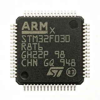
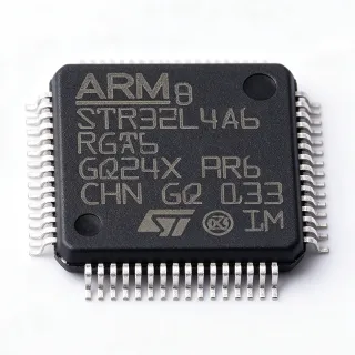
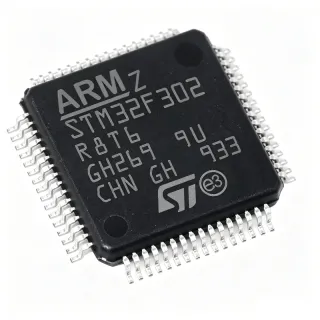
STM32F401RBT6 - ARM Cortex-M4 84MHz MCU | STMicroelectronics
MPN: STM32F401RBT6 ✓ AktifSTM32F401RBT6 Ringkasan
What is a microcontroller (MCU)? A microcontroller is a compact integrated circuit designed to govern a specific operation in an embedded system. It integrates a processor core, memory (Flash and SRAM), and programmable input/output peripherals on a single chip. In the system hierarchy, an MCU is a type of embedded processor, which falls under the broader category of integrated circuits. The STM32F401RBT6 is a mid-range MCU in the STM32F4 family, positioned between the entry-level STM32F0 and the high-performance STM32F7 series, offering a balance of performance, power efficiency, and cost.
Key features of the STM32F401RBT6 include an ARM Cortex-M4 core with FPU, 84 MHz maximum clock speed, 128 KB Flash, 64 KB SRAM, and a rich set of peripherals: 3 USARTs, 4 SPIs, 3 I2Cs, 1 USB 2.0 OTG FS, 1 SDIO, 1 ADC (12-bit, 16 channels), and multiple timers. It operates from a 1.7V to 3.6V power supply and supports a temperature range of -40°C to +85°C. The device includes a 12-bit ADC with up to 16 channels, enabling precise analog signal acquisition. It also features a true random number generator (RNG) and a CRC calculation unit for data integrity.
Technically, the STM32F401RBT6 is built on a 90nm process technology, offering a good balance of performance and power consumption. The Cortex-M4 core with FPU accelerates mathematical computations, making it suitable for DSP and control applications. The device supports multiple low-power modes (Sleep, Stop, Standby) to optimize energy consumption in battery-powered designs. The LQFP64 package provides 50 GPIOs, with many pins multiplexed to support various peripheral functions, offering design flexibility.
Typical applications include industrial control systems, motor drives, consumer electronics, IoT devices, and medical monitoring equipment. Its combination of processing power, peripheral set, and low-power modes makes it ideal for applications requiring real-time control and connectivity. For example, in a smart home gateway, the STM32F401RBT6 can manage sensor data acquisition, run communication protocols (e.g., Zigbee, Bluetooth), and control actuators.
When designing with this MCU, ensure proper decoupling of the power supply pins with 100nF capacitors placed close to each VDD pin, and a 4.7uF bulk capacitor. The VDDA pin should be filtered with a ferrite bead and capacitor to reduce analog noise. Also, configure the clock source (HSE or HSI) appropriately and use the PLL to achieve the desired system clock. For low-power applications, utilize the Stop and Standby modes with wake-up sources like RTC or external interrupts.
Alternatif penggantian untuk STM32F401RBT6 — paket yang sama, pin-pada-pin kompatibel. Bagian paket yang berbeda memerlukan kerja ulang PCB diabaikan.
Variasi di dalam seri ini
Model-series yang sama yang kompatibel dengan penggantian STM32F401RBT6 (sama faktor bentuk dan footprint) — berbeda di dalam Timers, ADC, Flash Memory, Package, SRAM.
STM32F401RCT6
✅ Drop-In ⚠️ Spesifikasi Tidak DisahkanKontak untuk harga
Lihat Datasheet →STM32F401RET6
✅ Drop-In ⚠️ Spesifikasi Tidak DisahkanKontak untuk harga
Lihat Datasheet →STM32F411RET6
✅ Drop-In ⚠️ Spesifikasi Tidak DisahkanKontak untuk harga
Lihat Datasheet →STM32F405RGT6
✅ Drop-In ⚠️ Spesifikasi Tidak DisahkanKontak untuk harga
Lihat Datasheet →ATSAMD51J19A
✅ Drop-In ⚠️ Spesifikasi Tidak Disahkan📋 Alternatif referensi (tidak dalam katalog)
LPC1768FBD100
✅ Drop-In ⚠️ Spesifikasi Tidak Disahkan📋 Alternatif referensi (tidak dalam katalog)
STM32F401RBT6 Rating Maksimal & Karakteristik Listrik
| Core | ARM Cortex-M4 with FPU |
| Maximum Clock Speed | 84 MHz |
| Flash Memory | 128 KB |
| SRAM | 64 KB |
| Tegangan Pemuat | 1.7 V to 3.6 V |
| Suhu Kerja | -40C to +85C |
| Paket | LQFP-64 (10x10 mm) |
| GPIO Pins | 50 |
| ADC | 12-bit, 16 channels |
| USART | 3 |
| SPI | 4 |
| I2C | 3 |
| USB | 1x USB 2.0 OTG FS |
| Timers | 8 (including advanced-control) |
| DMA | Yes, 8 channels |
| RTC | Yes |
| Low Power Modes | Sleep, Stop, Standby |
| RoHS | Compliant |
Konfigurasi Pin STM32F401RBT6
| Pin produk 1 | VBAT — Backup battery supply for RTC and backup registers |
| Pin produk 2 | PC13 — GPIO or RTC tamper/calendar |
| Pin produk 3 | PC14 — GPIO or OSC32_IN |
| Pin produk 4 | PC15 — GPIO or OSC32_OUT |
| Pin produk 5 | PF0 — GPIO or OSC_IN |
| Pin produk 6 | PF1 — GPIO or OSC_OUT |
| Pin produk 7 | NRST — Reset (active low) |
| Pin produk 8 | VSSA — Analog ground |
| Pin produk 9 | VDDA — Analog power supply |
| Pin produk 10 | PA0 — GPIO/ADC12_IN0/TIM2_CH1 |
| Pin produk 11 | PA1 — GPIO/ADC12_IN1/TIM2_CH2 |
| Pin produk 12 | PA2 — GPIO/ADC12_IN2/TIM2_CH3/USART2_TX |
| Pin produk 13 | PA3 — GPIO/ADC12_IN3/TIM2_CH4/USART2_RX |
| Pin produk 14 | VSS — Ground |
| Pin produk 15 | VDD — Power supply |
| Pin produk 16 | PA4 — GPIO/ADC12_IN4/SPI1_NSS |
| Pin produk 17 | PA5 — GPIO/ADC12_IN5/SPI1_SCK |
| Pin produk 18 | PA6 — GPIO/ADC12_IN6/SPI1_MISO |
| Pin produk 19 | PA7 — GPIO/ADC12_IN7/SPI1_MOSI |
| Pin produk 20 | PB0 — GPIO/ADC12_IN8/TIM3_CH3 |
| Pin produk 21 | PB1 — GPIO/ADC12_IN9/TIM3_CH4 |
| Pin produk 22 | PB2 — GPIO/BOOT1 |
| Pin produk 23 | PB10 — GPIO/I2C2_SCL/USART3_TX |
| Pin produk 24 | PB11 — GPIO/I2C2_SDA/USART3_RX |
| Pin produk 25 | VSS — Ground |
| Pin produk 26 | VDD — Power supply |
| Pin produk 27 | PB12 — GPIO/SPI2_NSS/I2C2_SMBA |
| Pin produk 28 | PB13 — GPIO/SPI2_SCK |
| Pin produk 29 | PB14 — GPIO/SPI2_MISO |
| Pin produk 30 | PB15 — GPIO/SPI2_MOSI |
| Pin produk 31 | PC6 — GPIO/TIM3_CH1/SDIO_D6 |
| Pin produk 32 | PC7 — GPIO/TIM3_CH2/SDIO_D7 |
| Pin produk 33 | PC8 — GPIO/TIM3_CH3/SDIO_D0 |
| Pin produk 34 | PC9 — GPIO/TIM3_CH4/SDIO_D1 |
| Pin produk 35 | PA8 — GPIO/USART1_CK/TIM1_CH1 |
| Pin produk 36 | PA9 — GPIO/USART1_TX/TIM1_CH2 |
| Pin produk 37 | PA10 — GPIO/USART1_RX/TIM1_CH3 |
| Pin produk 38 | PA11 — GPIO/USART1_CTS/USB_DM |
| Pin produk 39 | PA12 — GPIO/USART1_RTS/USB_DP |
| Pin produk 40 | PA13 — GPIO/SWDIO |
| Pin produk 41 | VSS — Ground |
| Pin produk 42 | VDD — Power supply |
| Pin produk 43 | PA14 — GPIO/SWCLK |
| Pin produk 44 | PA15 — GPIO/JTDI/TIM2_CH1 |
| Pin produk 45 | PB3 — GPIO/JTDO/TRACESWO |
| Pin produk 46 | PB4 — GPIO/NJTRST |
| Pin produk 47 | PB5 — GPIO/I2C1_SMBA |
| Pin produk 48 | PB6 — GPIO/I2C1_SCL/TIM4_CH1 |
| Pin produk 49 | PB7 — GPIO/I2C1_SDA/TIM4_CH2 |
| Pin produk 50 | BOOT0 — Boot mode selection |
| Pin produk 51 | PB8 — GPIO/I2C1_SCL/TIM4_CH3 |
| Pin produk 52 | PB9 — GPIO/I2C1_SDA/TIM4_CH4 |
| Pin produk 53 | VSS — Ground |
| Pin produk 54 | VDD — Power supply |
| Pin produk 55 | PC0 — GPIO/ADC12_IN10 |
| Pin produk 56 | PC1 — GPIO/ADC12_IN11 |
| Pin produk 57 | PC2 — GPIO/ADC12_IN12 |
| Pin produk 58 | PC3 — GPIO/ADC12_IN13 |
| Pin produk 59 | PC4 — GPIO/ADC12_IN14 |
| Pin produk 60 | PC5 — GPIO/ADC12_IN15 |
| Pin produk 61 | PB12 — GPIO/SPI2_NSS/I2C2_SMBA |
| Pin produk 62 | PB13 — GPIO/SPI2_SCK |
| Pin produk 63 | PB14 — GPIO/SPI2_MISO |
| Pin produk 64 | PB15 — GPIO/SPI2_MOSI |
Aplikasi Umum
STM32F401RBT6 cocok untuk 6 aplikasis: Industrial Control, IoT Devices, Consumer Electronics, Medical Monitoring, Automotive Aftermarket, Education and Prototyping.
Industrial Control
The STM32F401RBT6 is ideal for industrial control systems such as PLCs, motor drives, and robotic controllers. Its 84 MHz Cortex-M4 core with FPU accelerates real-time control algorithms, while the advanced timers generate precise PWM signals. The 12-bit ADC with 16 channels enables accurate sensor feedback. In a typical motor drive, the MCU reads current sensors via ADC, computes FOC, and outputs PWM to the inverter. The wide supply voltage range (1.7V-3.6V) and -40°C to +85°C operation ensure reliability in harsh environments. Compared to lower-end MCUs, the FPU reduces computation time for complex control loops, improving system responsiveness.
Direkomendasikan
IoT Devices
For IoT applications, the STM32F401RBT6 provides a balance of processing power and low-power modes. It supports Sleep, Stop, and Standby modes, with wake-up from RTC or external interrupts, enabling battery-powered devices to achieve long battery life. The USB 2.0 OTG FS interface allows direct connection to smartphones or PCs for data transfer and firmware updates. The 128 KB Flash is sufficient for communication stacks like MQTT, CoAP, or Bluetooth LE (via external module). In a smart home sensor node, the MCU periodically wakes from Stop mode, reads sensors, transmits data via a sub-GHz radio, and returns to sleep, consuming only microamps in standby. The rich peripheral set (USART, SPI, I2C) simplifies interfacing with various sensors and wireless modules.
Direkomendasikan
Consumer Electronics
The STM32F401RBT6 is widely used in consumer electronics such as smart appliances, wearables, and gaming peripherals. Its compact LQFP64 package and low power consumption make it suitable for space-constrained designs. The USB OTG interface enables direct connection to PCs for charging and data sync. The Cortex-M4 FPU accelerates audio processing, making it possible to implement simple audio effects or voice recognition. In a smart speaker, the MCU can handle audio codec control, button inputs, and LED indicators, while offloading heavy processing to a dedicated DSP. The 84 MHz clock ensures smooth user interface responsiveness. The device's wide operating voltage range allows it to be powered from a single Li-ion battery (3.3V) or USB 5V with an LDO.
Direkomendasikan
Medical Monitoring
In medical monitoring devices like patient vital sign monitors and portable ECG devices, the STM32F401RBT6 offers the processing power and analog capabilities needed for signal acquisition and processing. The 12-bit ADC with 16 channels can sample multiple biosignals simultaneously, while the Cortex-M4 FPU accelerates digital filtering and feature extraction. The low-power modes are crucial for battery-operated wearable monitors. For example, in a heart rate monitor, the MCU reads PPG sensor data via ADC, applies a bandpass filter, and computes heart rate using a peak detection algorithm. The USB interface allows data logging to a PC. The device's reliability and long-term availability make it suitable for medical applications, though certification (e.g., IEC 60601) is required for end products.
Direkomendasikan
Automotive Aftermarket
The STM32F401RBT6 is used in automotive aftermarket products such as car diagnostic tools, GPS trackers, and infotainment systems. Its robust design and wide temperature range (-40°C to +85°C) make it suitable for under-hood or cabin environments. The CAN interface (though not listed in the basic specs, it is available in some variants) can be added via external transceiver for OBD-II diagnostics. The USB OTG interface enables connection to smartphones for data display. In a GPS tracker, the MCU reads GPS data via UART, processes location information, and transmits it via a cellular module. The low-power modes help reduce battery drain when the vehicle is off. The device's rich peripheral set simplifies interfacing with GPS modules, cellular modems, and display controllers.
Direkomendasikan
Education and Prototyping
The STM32F401RBT6 is popular in education and rapid prototyping due to its low cost, availability, and extensive community support. It is used in development boards like the STM32F401RE Nucleo and Black Pill, which are widely used in university courses and maker projects. The STM32CubeIDE and HAL libraries simplify development, allowing students to focus on application logic. The device's performance is sufficient for learning RTOS, embedded C, and digital signal processing. In a robotics project, the MCU can control motors, read sensors, and implement PID control. The LQFP64 package is easy to solder with a hot-air station, and the 0.5mm pitch is manageable for hobbyists. The availability of many tutorials and examples accelerates the learning curve.
Direkomendasikan
Ringkasan Produk Direkomendasikan
Data referensi engineering untuk STM32F401RBT6 — pembandingan, panduan desain, dan informasi konformitas.
Panduan Pemilihan
Pembandingan dengan Alternatif
| Parameter Umum | Produk Ini | STM32F401RCT6 | STM32F401RET6 | STM32F411RET6 | STM32F405RGT6 | ATSAMD51J19A | LPC1768FBD100 |
|---|---|---|---|---|---|---|---|
| Package | LQFP-64 | LQFP-64 | LQFP-64 | LQFP-64 | LQFP-64 | LQFP-64 | LQFP-64 |
| Brand | STMicroelectronics | STMicroelectronics | STMicroelectronics | STMicroelectronics | STMicroelectronics | Microchip Technology | NXP Semiconductors |
| Core | ARM Cortex-M4 with FPU | ARM Cortex-M4 with FPU | ARM Cortex-M4 with FPU | ARM Cortex-M4 with FPU | ARM Cortex-M4 with FPU | ARM Cortex-M4F | ARM Cortex-M3 |
| Maximum Clock Speed | 84 MHz | 84 MHz | 84 MHz | 100 MHz | 168 MHz | 120 MHz | 100 MHz |
| Flash Memory | 128 KB | 256 KB | 512 KB | 512 KB | 1 MB | 512 KB | 512 KB |
| SRAM | 64 KB | 64 KB | 64 KB | 128 KB | 192 KB | 192 KB | 64 KB |
| ADC | 12-bit, 16 channels | 12-bit, 16 channels | 12-bit, 16 channels | 12-bit, 16 channels | 12-bit, 16 channels | 12-bit, 20 channels | 12-bit, 8 channels |
| USB | 1x USB 2.0 OTG FS | 1x USB 2.0 OTG FS | 1x USB 2.0 OTG FS | 1x USB 2.0 OTG FS | 1x USB 2.0 OTG FS | 1x USB 2.0 | 1x USB 2.0 FS/HS |
Diferensiator Kunci
- Higher clock speed than STM32F401RCT6 (vsSTM32F401RCT6)
- Lower power consumption than STM32F411RET6 (vsSTM32F411RET6)
- Better ecosystem and software support than ATSAMD51J19A (vsATSAMD51J19A)
Catatan Desain
Decouple each VDD pin with a 100nF ceramic capacitor placed as close as possible to the pin, and add a 4.7uF bulk capacitor. The VDDA pin should be connected to VDD through a ferrite bead and a 1uF capacitor to filter analog noise. Ensure VSSA is connected to ground with a low-impedance path. For battery-powered designs, use the VBAT pin for RTC backup and connect a 3V coin cell.
For the LQFP64 package, use a 4-layer PCB with a solid ground plane. Place the crystal (HSE) and load capacitors close to the OSC_IN/OSC_OUT pins, with a ground guard ring to reduce noise. Keep high-speed signals (e.g., SPI, USB) away from the crystal and analog pins. Use via stitching around the ground plane to minimize EMI.
Ensure the BOOT0 pin is properly configured: tie to GND for normal boot from Flash, or to VDD for boot from system memory. Do not leave NRST floating; connect a 100nF capacitor to GND. When using the ADC, set the sampling time appropriately for the source impedance to avoid inaccurate readings. Also, configure the PLL correctly to avoid exceeding the maximum clock speed of 84 MHz.
Informasi Konformitas
RoHS compliant per STMicroelectronics product page. Not AEC-Q100 qualified; for automotive, consider STM32F401RBT6Q or other automotive-grade variants.