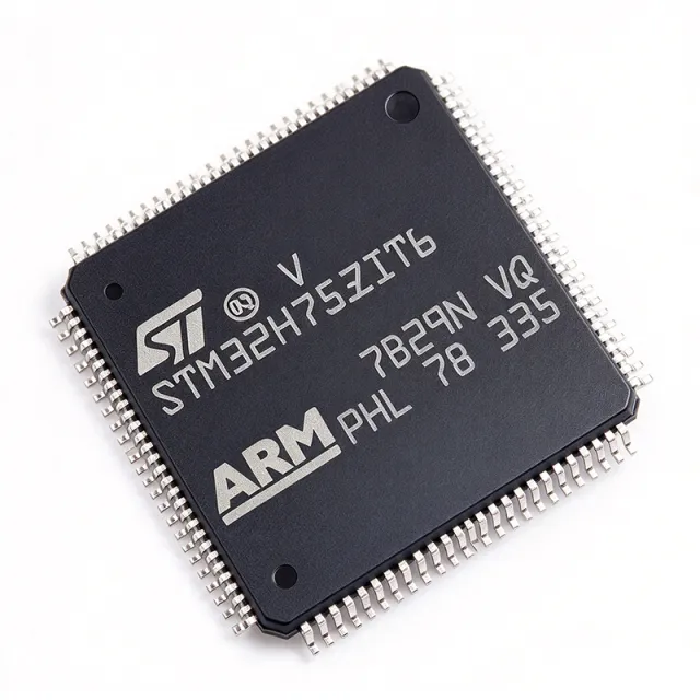
STM32H753ZIT6 - 480MHz Cortex-M7 MCU, 2MB Flash | STMicroelectronics
MPN: STM32H753ZIT6 ✓ AktifSTM32H753ZIT6 Ringkasan
A microcontroller (MCU) is a compact integrated circuit that combines a processor core, non-volatile program memory, volatile data memory, and programmable peripherals on a single die, allowing it to govern a dedicated embedded function without external support chips. The STM32H753ZIT6 sits at the top of the STM32H7 hierarchy: Cortex-M7 core -> STM32H7 series -> STM32 32-bit MCU family -> embedded microcontroller -> semiconductor. This position makes it the natural upgrade path from Cortex-M4/M3 designs that have run out of compute headroom.
Key differentiators include the 480 MHz Cortex-M7 core with DSP and double-precision FPU instructions, 2 MB dual-bank Flash supporting read-while-write for live firmware updates, 1 MB SRAM, and a rich connectivity set: Ethernet MAC, USB OTG HS/FS, CAN FD, and multiple USART/SPI/I2C instances. A 16-bit ADC at 3.6 MSPS, a 12-bit DAC, and advanced motor-control timers round out the analog and control capability.
Technically, the device is fabricated on a 40 nm process and operates from a 1.62 V to 3.6 V supply over -40 C to +85 C. An on-chip power management unit provides Sleep, Stop, and Standby modes for battery-powered designs, while the integrated LDO/SMPS regulator architecture differs from earlier STM32F7 designs that used a BYPASS_REG pin.
Typical applications include industrial automation (PLCs, robotics), motor control (drives, pumps), medical devices (patient monitors, infusion pumps), and high-end audio equipment. The high clock speed and DSP instructions suit real-time signal processing, while the Chrom-ART Accelerator supports advanced graphical user interfaces.
When designing with this MCU, decouple every VDD pin with a 100 nF capacitor placed close to the pin plus a 4.7 uF bulk capacitor, and feed VDDA through a ferrite bead from a dedicated analog supply. For Ethernet and USB HS, follow the STM32H7 reference manual (RM0433) layout guidance to preserve signal integrity.
This page synthesizes distributor pricing, drop-in alternatives, and practical design notes not found in the manufacturer datasheet, giving engineers a single reference for selection, second-sourcing, and layout decisions.
Alternatif penggantian untuk STM32H753ZIT6 — paket yang sama, pin-pada-pin kompatibel. Bagian paket yang berbeda memerlukan kerja ulang PCB diabaikan.
Variasi di dalam seri ini
Model-series yang sama yang kompatibel dengan penggantian STM32H753ZIT6 (sama faktor bentuk dan footprint) — berbeda di dalam Operating Temperature, Package, ADC, Communication Interfaces, SRAM.
STM32H743ZIT6
Kontak untuk harga
Lihat Datasheet →STM32H753IIT6
Kontak untuk harga
Lihat Datasheet →STM32H753BGT6
Kontak untuk harga
Lihat Datasheet →STM32H745IIT6
Kontak untuk harga
Lihat Datasheet →STM32H750ZBT6
Kontak untuk harga
Lihat Datasheet →STM32H753ZIT6 Rating Maksimal & Karakteristik Listrik
| Core Architecture | Arm Cortex-M7 32-bit RISC |
| Maximum CPU Frequency | 480 MHz |
| Floating Point Unit | Double-precision (IEEE 754 compliant) |
| Program Memory (Flash) | 2 MB dual-bank |
| RAM | 1 MB SRAM |
| Supply Voltage Range | 1.62 V to 3.6 V |
| Suhu Kerja | -40 C to +85 C |
| Paket | LQFP-144 (20x20 mm, 0.5 mm pitch) |
| Jumlah Pin | 144 |
| Process Technology | 40 nm |
| ADC | 16-bit, 3.6 MSPS |
| DAC | 12-bit |
| Ethernet | 10/100 MAC with DMA |
| USB | OTG HS/FS |
| CAN | CAN FD |
| Graphics Accelerator | Chrom-ART Accelerator (2D) |
| Cryptographic Accelerator | Hardware crypto processor |
| Low-Power Modes | Sleep, Stop, Standby |
| Tipe Mounting | Surface Mount |
| Status RoHS | Compliant |
Konfigurasi Pin STM32H753ZIT6
| Pin produk 1 | PE2 — GPIO port E bit 2 |
| Pin produk 2 | PE3 — GPIO port E bit 3 |
| Pin produk 3 | PE4 — GPIO port E bit 4 |
| Pin produk 4 | PE5 — GPIO port E bit 5 |
| Pin produk 5 | PE6 — GPIO port E bit 6 |
| Pin produk 6 | VBAT — Backup domain supply |
| Pin produk 7 | PC13 — GPIO port C bit 13 |
| Pin produk 8 | PC14-OSC32_IN — GPIO / 32.768 kHz crystal input |
| Pin produk 9 | PC15-OSC32_OUT — GPIO / 32.768 kHz crystal output |
| Pin produk 10 | PF0 — GPIO port F bit 0 |
| Pin produk 11 | PF1 — GPIO port F bit 1 |
| Pin produk 12 | PF2 — GPIO port F bit 2 |
| Pin produk 13 | PF3 — GPIO port F bit 3 |
| Pin produk 14 | PF4 — GPIO port F bit 4 |
| Pin produk 15 | PF5 — GPIO port F bit 5 |
| Pin produk 16 | VSS — Ground |
| Pin produk 17 | VDD — Digital power supply |
| Pin produk 18 | PF6 — GPIO port F bit 6 |
| Pin produk 19 | PF7 — GPIO port F bit 7 |
| Pin produk 20 | PF8 — GPIO port F bit 8 |
| Pin produk 21 | PF9 — GPIO port F bit 9 |
| Pin produk 22 | PF10 — GPIO port F bit 10 |
| Pin produk 23 | PH0-OSC_IN — GPIO / HSE crystal input |
| Pin produk 24 | PH1-OSC_OUT — GPIO / HSE crystal output |
| Pin produk 25 | NRST — Reset input (active low) |
| Pin produk 26 | PC0 — GPIO port C bit 0 |
| Pin produk 27 | PC1 — GPIO port C bit 1 |
| Pin produk 28 | PC2_C — GPIO / analog input |
| Pin produk 29 | PC3_C — GPIO / analog input |
| Pin produk 30 | VDD — Digital power supply |
| Pin produk 31 | VSSA — Analog ground |
| Pin produk 32 | VREF+ — ADC/DAC reference voltage |
| Pin produk 33 | VDDA — Analog power supply |
| Pin produk 34 | PA0 — GPIO port A bit 0 |
| Pin produk 35 | PA1 — GPIO port A bit 1 |
| Pin produk 36 | PA2 — GPIO port A bit 2 |
| Pin produk 37 | PA3 — GPIO port A bit 3 |
| Pin produk 38 | VSS — Ground |
| Pin produk 39 | VDD — Digital power supply |
| Pin produk 40 | PA4 — GPIO port A bit 4 |
| Pin produk 41 | PA5 — GPIO port A bit 5 |
| Pin produk 42 | PA6 — GPIO port A bit 6 |
| Pin produk 43 | PA7 — GPIO port A bit 7 |
| Pin produk 44 | PC4 — GPIO port C bit 4 |
| Pin produk 45 | PC5 — GPIO port C bit 5 |
| Pin produk 46 | PB0 — GPIO port B bit 0 |
| Pin produk 47 | PB1 — GPIO port B bit 1 |
| Pin produk 48 | PB2 — GPIO port B bit 2 |
| Pin produk 49 | PF11 — GPIO port F bit 11 |
| Pin produk 50 | PF12 — GPIO port F bit 12 |
| Pin produk 51 | VSS — Ground |
| Pin produk 52 | VDD — Digital power supply |
| Pin produk 53 | PF13 — GPIO port F bit 13 |
| Pin produk 54 | PF14 — GPIO port F bit 14 |
| Pin produk 55 | PF15 — GPIO port F bit 15 |
| Pin produk 56 | PG0 — GPIO port G bit 0 |
| Pin produk 57 | PG1 — GPIO port G bit 1 |
| Pin produk 58 | PE7 — GPIO port E bit 7 |
| Pin produk 59 | PE8 — GPIO port E bit 8 |
| Pin produk 60 | PE9 — GPIO port E bit 9 |
| Pin produk 61 | VSS — Ground |
| Pin produk 62 | VDD — Digital power supply |
| Pin produk 63 | PE10 — GPIO port E bit 10 |
| Pin produk 64 | PE11 — GPIO port E bit 11 |
| Pin produk 65 | PE12 — GPIO port E bit 12 |
| Pin produk 66 | PE13 — GPIO port E bit 13 |
| Pin produk 67 | PE14 — GPIO port E bit 14 |
| Pin produk 68 | PE15 — GPIO port E bit 15 |
| Pin produk 69 | PB10 — GPIO port B bit 10 |
| Pin produk 70 | PB11 — GPIO port B bit 11 |
| Pin produk 71 | VCAP — Core regulator capacitor |
| Pin produk 72 | VDD — Digital power supply |
| Pin produk 73 | PB12 — GPIO port B bit 12 |
| Pin produk 74 | PB13 — GPIO port B bit 13 |
| Pin produk 75 | PB14 — GPIO port B bit 14 |
| Pin produk 76 | PB15 — GPIO port B bit 15 |
| Pin produk 77 | PD8 — GPIO port D bit 8 |
| Pin produk 78 | PD9 — GPIO port D bit 9 |
| Pin produk 79 | PD10 — GPIO port D bit 10 |
| Pin produk 80 | PD11 — GPIO port D bit 11 |
| Pin produk 81 | PD12 — GPIO port D bit 12 |
| Pin produk 82 | PD13 — GPIO port D bit 13 |
| Pin produk 83 | VSS — Ground |
| Pin produk 84 | VDD — Digital power supply |
| Pin produk 85 | PD14 — GPIO port D bit 14 |
| Pin produk 86 | PD15 — GPIO port D bit 15 |
| Pin produk 87 | PG2 — GPIO port G bit 2 |
| Pin produk 88 | PG3 — GPIO port G bit 3 |
| Pin produk 89 | PG4 — GPIO port G bit 4 |
| Pin produk 90 | PG5 — GPIO port G bit 5 |
| Pin produk 91 | PG6 — GPIO port G bit 6 |
| Pin produk 92 | PG7 — GPIO port G bit 7 |
| Pin produk 93 | PG8 — GPIO port G bit 8 |
| Pin produk 94 | VSS — Ground |
| Pin produk 95 | VDD — Digital power supply |
| Pin produk 96 | PC6 — GPIO port C bit 6 |
| Pin produk 97 | PC7 — GPIO port C bit 7 |
| Pin produk 98 | PC8 — GPIO port C bit 8 |
| Pin produk 99 | PC9 — GPIO port C bit 9 |
| Pin produk 100 | PA8 — GPIO port A bit 8 |
| Pin produk 101 | PA9 — GPIO port A bit 9 |
| Pin produk 102 | PA10 — GPIO port A bit 10 |
| Pin produk 103 | PA11 — GPIO port A bit 11 |
| Pin produk 104 | PA12 — GPIO port A bit 12 |
| Pin produk 105 | PA13 — GPIO port A bit 13 |
| Pin produk 106 | VSS — Ground |
| Pin produk 107 | VDD — Digital power supply |
| Pin produk 108 | PA14 — GPIO port A bit 14 |
| Pin produk 109 | PA15 — GPIO port A bit 15 |
| Pin produk 110 | PC10 — GPIO port C bit 10 |
| Pin produk 111 | PC11 — GPIO port C bit 11 |
| Pin produk 112 | PC12 — GPIO port C bit 12 |
| Pin produk 113 | PD0 — GPIO port D bit 0 |
| Pin produk 114 | PD1 — GPIO port D bit 1 |
| Pin produk 115 | PD2 — GPIO port D bit 2 |
| Pin produk 116 | PD3 — GPIO port D bit 3 |
| Pin produk 117 | PD4 — GPIO port D bit 4 |
| Pin produk 118 | PD5 — GPIO port D bit 5 |
| Pin produk 119 | VSS — Ground |
| Pin produk 120 | VDD — Digital power supply |
| Pin produk 121 | PD6 — GPIO port D bit 6 |
| Pin produk 122 | PD7 — GPIO port D bit 7 |
| Pin produk 123 | PG9 — GPIO port G bit 9 |
| Pin produk 124 | PG10 — GPIO port G bit 10 |
| Pin produk 125 | PG11 — GPIO port G bit 11 |
| Pin produk 126 | PG12 — GPIO port G bit 12 |
| Pin produk 127 | PG13 — GPIO port G bit 13 |
| Pin produk 128 | PG14 — GPIO port G bit 14 |
| Pin produk 129 | VSS — Ground |
| Pin produk 130 | VDD — Digital power supply |
| Pin produk 131 | PG15 — GPIO port G bit 15 |
| Pin produk 132 | PB3 — GPIO port B bit 3 |
| Pin produk 133 | PB4 — GPIO port B bit 4 |
| Pin produk 134 | PB5 — GPIO port B bit 5 |
| Pin produk 135 | PB6 — GPIO port B bit 6 |
| Pin produk 136 | PB7 — GPIO port B bit 7 |
| Pin produk 137 | BOOT0 — Boot mode selection |
| Pin produk 138 | PB8 — GPIO port B bit 8 |
| Pin produk 139 | PB9 — GPIO port B bit 9 |
| Pin produk 140 | PE0 — GPIO port E bit 0 |
| Pin produk 141 | PE1 — GPIO port E bit 1 |
| Pin produk 142 | VSS — Ground |
| Pin produk 143 | VDD — Digital power supply |
| Pin produk 144 | PDR_ON — Power-down reset enable |
Aplikasi Umum
STM32H753ZIT6 cocok untuk 6 aplikasis: Industrial Automation and PLCs, Motor Control and Drives, Medical Devices and Patient Monitors, Edge AI and Real-Time Signal Processing, High-End Audio and Graphical HMI, Networking and Communication Gateways.
Industrial Automation and PLCs
The STM32H753ZIT6 fits industrial programmable logic controllers because its 480 MHz Cortex-M7 core executes ladder-logic and motion-control loops with deterministic timing, while the 2 MB dual-bank Flash allows firmware updates without stopping the production line. Ethernet MAC and CAN FD interfaces connect directly to plant networks and fieldbus segments, and the 16-bit 3.6 MSPS ADC digitizes analog sensor inputs for process control. In a typical PLC design the MCU sits between isolated digital I/O and the backplane bus, running a real-time operating system. The trade-off is power: at 480 MHz the core draws substantially more than a Cortex-M4, so thermal vias and a copper pour under the LQFP-144 exposed pad are recommended for sealed enclosures.
Direkomendasikan
Motor Control and Drives
The STM32H753ZIT6 is designed for field-oriented control of three-phase motors: its advanced timers generate complementary PWM with programmable dead-time, the 16-bit ADC samples phase currents at 3.6 MSPS to close the current loop, and the Cortex-M7 DSP instructions execute Park/Clarke transforms in a few cycles. At 480 MHz the device can run PWM frequencies above 20 kHz while still leaving headroom for position-loop and communication tasks. The dual-bank Flash enables over-the-air firmware updates in pumps and drives that cannot be taken offline. Designers should note that the integrated SMPS/LDO regulator architecture differs from STM32F7 parts, so the power-supply schematic must be reworked when migrating from an F7 design.
Direkomendasikan
Medical Devices and Patient Monitors
The STM32H753ZIT6 suits patient monitors and infusion pumps because the hardware cryptographic accelerator provides secure boot and encrypted firmware storage, a requirement for connected medical equipment, while the 16-bit ADC and 12-bit DAC handle physiological signal acquisition and calibration output. The 2 MB dual-bank Flash supports fail-safe firmware updates in devices that must remain certified and available. In a monitor design the MCU processes ECG or SpO2 sample streams in real time and drives a graphical display through the Chrom-ART Accelerator. The main trade-off is that the -40 C to +85 C industrial grade is not AEC-Q100 qualified, so automotive-grade medical platforms should evaluate the STM32H7 automotive variants instead.
Direkomendasikan
Edge AI and Real-Time Signal Processing
The STM32H753ZIT6 brings edge-AI inference to embedded systems through its 480 MHz Cortex-M7 core with double-precision FPU and DSP extensions, which accelerate neural-network kernels and FIR/FFT filtering without an external accelerator. 1 MB of SRAM holds intermediate tensors for small convolutional models, and the 2 MB Flash stores weights and application code. In a predictive-maintenance node the MCU runs vibration FFT analysis and a classifier locally, sending only results over Ethernet or CAN FD. The trade-off versus a dedicated NPU is throughput per watt: the Cortex-M7 is flexible but slower than a fixed-function accelerator, so designers should profile model latency before committing to this part.
Direkomendasikan
High-End Audio and Graphical HMI
The STM32H753ZIT6 supports high-end audio and graphical user interfaces because the Chrom-ART Accelerator offloads 2D blitting and alpha-blending from the CPU, allowing smooth display updates on TFT panels while the Cortex-M7 core runs audio DSP. The 12-bit DAC and I2S/SAI peripherals interface directly to audio codecs, and the 480 MHz core executes sample-rate conversion and equalization in real time. In an audio mixer the MCU handles USB audio streaming, DSP effects, and a touchscreen UI concurrently. The design consideration is memory bandwidth: driving a large RGB display from internal SRAM competes with audio buffers, so external SDRAM via the FMC is often added for framebuffer storage.
Direkomendasikan
Networking and Communication Gateways
The STM32H753ZIT6 is used in industrial gateways and protocol converters because it integrates a 10/100 Ethernet MAC with DMA, USB OTG HS/FS, and CAN FD on a single die, eliminating external bridge chips. The 480 MHz core runs TCP/IP stacks, Modbus, and protocol translation with low latency, while the hardware crypto accelerator offloads TLS handshakes for secure cloud connectivity. In a gateway design the MCU bridges a CAN FD fieldbus to an Ethernet backhaul, buffering frames in the 1 MB SRAM. The trade-off is that the integrated Ethernet MAC requires an external PHY and magnetics, so board area and BOM cost must account for those components plus the RM0433-recommended layout practices.
Direkomendasikan
Ringkasan Produk Direkomendasikan
Data referensi engineering untuk STM32H753ZIT6 — pembandingan, panduan desain, dan informasi konformitas.
Panduan Pemilihan
Pembandingan dengan Alternatif
| Parameter Umum | Produk Ini | STM32H743ZIT6 | STM32H753IIT6 | STM32H750ZBT6 | STM32H753BGT6 | STM32H745IIT6 |
|---|---|---|---|---|---|---|
| Package | LQFP-144 | LQFP-144 - same | LQFP-176 | LQFP-144 - same | LQFP-208 | LQFP-176 |
| Brand | STMicroelectronics | STMicroelectronics | STMicroelectronics | STMicroelectronics | STMicroelectronics | STMicroelectronics |
| Core / Frequency | Cortex-M7 @ 480 MHz | Cortex-M7 @ 480 MHz | Cortex-M7 @ 480 MHz | Cortex-M7 @ 480 MHz | Cortex-M7 @ 480 MHz | Cortex-M7 @ 480 MHz + Cortex-M4 @ 240 MHz |
| Flash Memory | 2 MB dual-bank | 2 MB dual-bank | 2 MB dual-bank | 128 KB | 2 MB dual-bank | 2 MB dual-bank |
| SRAM | 1 MB | 1 MB | 1 MB | 1 MB | 1 MB | 1 MB |
| Hardware Crypto Accelerator | Yes (AES, HASH, RNG) | No | Yes | No | Yes | No |
| Ethernet MAC | 10/100 with DMA | 10/100 with DMA | 10/100 with DMA | 10/100 with DMA | 10/100 with DMA | 10/100 with DMA |
| Supply Voltage | 1.62 V to 3.6 V | 1.62 V to 3.6 V | 1.62 V to 3.6 V | 1.62 V to 3.6 V | 1.62 V to 3.6 V | 1.62 V to 3.6 V |
| Operating Temperature | -40 C to +85 C | -40 C to +85 C | -40 C to +85 C | -40 C to +85 C | -40 C to +85 C | -40 C to +85 C |
Diferensiator Kunci
- Hardware cryptographic accelerator integrated on-die (vsSTM32H743ZIT6)
- 2 MB dual-bank Flash with read-while-write (vsSTM32H750ZBT6)
- Single-core Cortex-M7 with full 480 MHz headroom (vsSTM32H745IIT6)
Catatan Desain
Decouple every VDD pin with a 100 nF ceramic capacitor placed as close to the pin as possible, plus at least one 4.7 uF bulk capacitor per supply domain. Feed VDDA through a ferrite bead from the digital 3.3 V rail and add a dedicated 100 nF plus 1 uF capacitor at the VDDA pin. The VCAP pin requires the regulator stabilization capacitor specified in the STM32H753xI datasheet; omitting it prevents the internal core regulator from starting.
Route the 32.768 kHz and HSE crystal traces as short, symmetric, guarded pairs with a solid ground reference directly beneath them, and keep switching nodes such as the SMPS inductor away from the crystal and analog pins. For the LQFP-144 land pattern, use the manufacturer-recommended pad geometry and place a grid of thermal vias under the exposed pad to spread heat into an internal ground plane.
Estimated: migrating from an STM32F7 design requires power-supply rework because the H7 uses an integrated LDO/SMPS regulator with software-controlled power modes instead of the F7 BYPASS_REG pin. Also verify BOOT0 and PDR_ON strapping before first power-up, and confirm that any security-peripheral initialization code is present when moving from STM32H743 to STM32H753, since the crypto block is the only functional difference.
Informasi Konformitas
RoHS and REACH compliance confirmed from distributor listings. The STM32H753ZIT6 is industrial grade (-40 C to +85 C) and is not AEC-Q100 qualified; automotive designs should evaluate STM32H7 automotive-grade variants.





