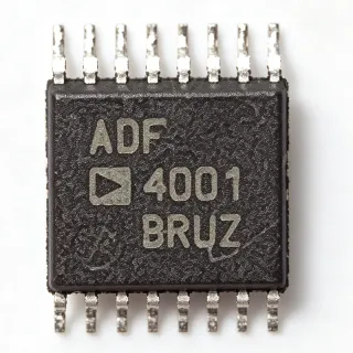
AD5316ARU - Quad 10-Bit DAC, 2.5-5.5V | Analog Devices
부품 번호: AD5316ARU ✓ 활성AD5316ARU 개요
A digital-to-analog converter is an interface IC that converts digital control words into proportional analog voltages. The AD5316 belongs to the DAC hierarchy, where it sits between a digital bus and precision analog test, control, or instrumentation circuitry. Its buffered outputs reduce the need for external output amplifiers when driving moderate loads.
The four converters provide 10-bit resolution, and the A-grade device has an integral nonlinearity specification of ±4 LSB. On-chip output amplifiers support rail-to-rail output swing with a slew rate of 0.7 V/µs. The single-supply operating range covers both 3.3 V and 5 V systems, while the typical supply current is 500 µA at 3 V for low-power portable and industrial designs.
The AD5316 uses a 2-wire serial interface operating up to 400 kHz and is compatible with SMBus-style communication. Each channel provides an independently programmable output voltage through its corresponding DAC register. The interface allows a microcontroller, embedded processor, or programmable controller to update four analog outputs while minimizing the number of signal connections required on the PCB.
Typical applications include process-control setpoints, automated test equipment, sensor excitation and bias control, industrial data acquisition, programmable laboratory supplies, and low-power embedded instrumentation. The quad-channel arrangement is particularly useful when a system requires several independently controlled analog outputs but has limited connector and routing space.
PCB design should keep the serial interface and output routing compact while observing the analog-ground and supply-return paths recommended in the manufacturer datasheet. Decoupling capacitance should be placed close to the supply pins, and output loads should be checked against the buffered-output capabilities. The 0.7 V/µs slew rate should also be considered when designing waveforms that require rapid output transitions.
This page combines the manufacturer's device characteristics, package and interface details, comparison guidance, and practical application guidance to help engineers evaluate the AD5316ARU without relying only on a basic catalog listing.
드롭인 대체품: AD5316ARU — 동일 패키지, 핀 호환. PCB 재작업이 필요한 다른 패키지 부품은 제외됩니다.
AD5316ARUZ
✅ 드롭인📋 참조 대체품 (카탈로그에 없음)
AD5316ARU-REEL7
✅ 드롭인📋 참조 대체품 (카탈로그에 없음)
AD5306ARUZ
✅ 드롭인📋 참조 대체품 (카탈로그에 없음)
AD5317BRUZ
✅ 드롭인📋 참조 대체품 (카탈로그에 없음)
AD5316RBRUZ
✅ 드롭인📋 참조 대체품 (카탈로그에 없음)
AD5316ARU 최대 정격 & 전기적 특성
| Number of DAC Channels | 4 channels |
| DAC Resolution | 10 bits |
| Supply Voltage Range | 2.5 V to 5.5 V |
| Typical Supply Current | 500 µA at 3 V |
| 출력 유형 | Buffered voltage output |
| Output Swing | Rail-to-rail |
| Output Slew Rate | 0.7 V/µs |
| Integral Nonlinearity | ±4 LSB for A grade |
| Serial Interface | 2-wire serial interface |
| Maximum Serial Clock Rate | 400 kHz |
| Serial Interface Compatibility | SMBus-compatible |
| Reference Type | External reference |
| 패키지 | 16-lead TSSOP |
| 핀 수 | 16 pins |
| 실장 유형 | Surface mount |
| 동작 온도 범위 | -40 °C to +105 °C |
| Screening Level | Industrial |
| Power Dissipation | 2.5 mW |
| RoHS 상태 | unknown |
| REACH Status | unknown |
AD5316ARU 16-lead tssop 핀 구성 가이드
AD5316ARU(16-lead tssop 패키지)의 핀 구성입니다. 이 아날로그 부품에는 입력, 출력, 전원 공급 핀이 있습니다. 오프셋 널, 보상, 인에이블 핀 구성은 제조사 데이터시트를 참조하십시오. 신호 컨디셔닝 및 증폭기 회로에 이상적입니다.

다음에 대한 상세 핀아웃 데이터 없음: AD5316ARU.
다음을 참조하십시오: 데이터시트 전체 핀 구성은 다음을 참조하십시오.
일반적인 애플리케이션
AD5316ARU 적합 용도: 6 애플리케이션s: Industrial Process Control, Programmable Test Equipment, Sensor Excitation and Biasing, Programmable Laboratory Supplies, Data Acquisition Systems, Embedded Instrumentation.
Industrial Process Control
The AD5316ARU fits four-channel process-control systems that must convert digital setpoints into analog actuator commands. Its 10-bit resolution provides 1,024 codes per channel, while the four buffered outputs allow multiple control loops to share one controller. The 2-wire interface operates up to 400 kHz, reducing wiring in distributed control equipment, and the 2.5 V to 5.5 V supply range supports both 3.3 V and 5 V industrial controller platforms. Verify the external reference, output range, and load impedance against each loop before production deployment.
추천
Programmable Test Equipment
The AD5316ARU can generate up to four independent analog test stimuli in programmable instrumentation. A 10-bit command word gives each channel 1,024 output levels, which is useful for coarse source calibration, relay or amplifier control, and fixture biasing. Its 400 kHz 2-wire interface allows a test controller to load a sequence of channel values efficiently, while buffered outputs reduce the need for separate output amplifiers. For metrology paths demanding finer resolution, use a higher-resolution DAC and recalibrate the source path.
추천
Sensor Excitation and Biasing
The AD5316ARU is suitable for multi-channel sensor-bias and excitation systems where four independently adjustable voltages are needed. By placing each DAC output near the associated input network, the 2-wire architecture reduces routing across a measurement board. The 0.7 V/µs output slew rate supports relatively quick settling after code changes, and the low 500 µA typical supply current at 3 V suits compact acquisition modules. Confirm output settling at the required accuracy and ensure the external reference does not introduce noise into the measurement front end.
추천
Programmable Laboratory Supplies
A laboratory supply controller can use the AD5316ARU to generate four low-level voltage commands for DUT bias, limit setting, or calibration fixtures. The device's 10-bit resolution and rail-to-rail buffered outputs are appropriate when the control path does not require ultra-high precision. Since the outputs are voltage commands rather than direct power-stage drivers, the design should add appropriate amplifiers when driving heavier loads. The 400 kHz serial rate permits coordinated multi-channel updates, which is useful for matching polarity or level changes across a fixture.
추천
Data Acquisition Systems
The AD5316ARU can supply programmable control or excitation voltages in compact data-acquisition equipment. Four channels let the acquisition controller manage several analog output functions without allocating a separate DAC package for each signal. The 2.5 V minimum supply supports low-voltage embedded designs, while the typical 500 µA current at 3 V helps limit power demand. The serial interface should be routed away from high-gain analog inputs, and the reference and DAC return paths should be arranged according to the manufacturer's layout guidance.
추천
Embedded Instrumentation
The AD5316ARU is appropriate for embedded instrumentation that needs multiple analog control outputs without adding extensive digital wiring. Its four 10-bit channels and SMBus-compatible 2-wire interface align with microcontroller-based instrumentation, while the TSSOP-16 package supports compact board layouts. The buffered outputs can drive normal instrumentation signal-conditioning inputs, but external buffering may be required for high capacitance or long cable runs. Account for the 0.7 V/µs slew rate when sequencing commands through switched test paths.
추천
추천 제품 요약
엔지니어링 참조 데이터: AD5316ARU — 비교, 설계 지침 및 규정 준수 정보.
선택 가이드
대체품과의 비교
| 파라미터 | 이 제품 | AD5316ARUZ | AD5316ARU-REEL7 | AD5306ARUZ | AD5317BRUZ | AD5316RBRUZ |
|---|---|---|---|---|---|---|
| Package | TSSOP-16 | TSSOP-16 | TSSOP-16 | TSSOP-16 | TSSOP-16 | TSSOP-16 |
| Brand | Analog Devices | Analog Devices | Analog Devices | Analog Devices | Analog Devices | Analog Devices |
| Number of DAC Channels | 4 channels | 4 channels | 4 channels | 4 channels | 4 channels | 4 channels |
주요 차별점
- Exact AD5316ARU ordering configuration (vs AD5316ARUZ)
- Balanced resolution for multichannel control (vs AD5306ARUZ)
- External-reference architecture (vs AD5316RBRUZ)
설계 노트
Place the supply bypass capacitor directly between the supply and ground pins, and keep the external reference and reference-return traces short. Route the 2-wire interface away from the four analog outputs and sensitive input circuits. The TSSOP-16 footprint is compact, so leaving adequate spacing around the pins improves soldering access and reduces the chance of accidental bridges between adjacent nets.
Use the manufacturer pin-description table when assigning the SDA-like clock, SCL-like data, reference, supply, ground, and four analog-output nets. Verify that each output trace has a return path and is not routed beside a switching node. If an output drives a capacitive load, keep the load modest or add an isolation resistor and external buffer because the 0.7 V/µs slew rate can produce edge-related settling and crosstalk.
Do not treat a family member with the same package as automatically interchangeable. Confirm pin numbering, accuracy grade, temperature rating, reference voltage, output range, interface protocol, and ordering suffix before replacing the AD5316ARU. The AD5316R family adds an internal reference and power-on-reset functionality, so its control behavior may differ even though all listed alternatives use a TSSOP-16 package.
규정 준수 정보
The device is described as an industrial-grade component, but no specific RoHS, REACH, halogen-free, lead-free, or conflict-minerals declaration is stated on the manufacturer product page. The AD5316ARU is not presented as an AEC-Q100-qualified automotive device.