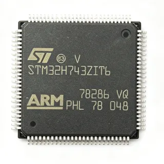
ATSAME70Q19A-AN - ARM Cortex-M7 MCU 300MHz 512KB | Microchip
MPN: ATSAME70Q19A-AN ✓ Active| Qty | Unit Price | Extended |
|---|---|---|
| 1 | $17.59 | $17.59 |
| 10 | $15.83 | $158.30 |
| 100 | $14.2 | $1,420.00 |
| 500 | $12.75 | $6,375.00 |
| 1,000 | $11.4 | $11,400.00 |
| 2,500 | $10.55 | $26,375.00 |
ATSAME70Q19A-AN Overview
An ARM Cortex-M7 microcontroller is a 32-bit RISC processor core designed by ARM that combines high clock speed with single-precision and double-precision floating-point hardware, optional SIMD DSP extensions, and tightly-coupled memories (TCM) that allow deterministic zero-wait-state code execution. The Cortex-M7 sits at the top of the Cortex-M family, positioned above Cortex-M4 in performance and below Cortex-A application processors. Microcontrollers integrating M7 belong to the broader category of embedded microcontrollers (MCU), a superset of microprocessors that bundles CPU, RAM, Flash, and peripherals into a single IC.
Key features include a 300 MHz Cortex-M7 core with double-precision FPU, 16 KB I-cache and 16 KB D-cache, 384 KB of additional SRAM in addition to the 256 KB system SRAM, up to 512 KB Flash, an EMAC 10/100 Ethernet MAC, dual CAN-FD controllers, a 12-bit ADC with up to 24 channels, a high-speed USB Host/Device plus PHY, an image sensor interface, and a TFT LCD controller. The device operates from 1.62 V to 3.6 V I/O and supports industrial-grade temperature ranges.
The ATSAME70Q19A-AN leverages superscalar pipeline architecture with branch prediction, hardware multiply-accumulate, and tightly-coupled instruction/data memories. The Ethernet MAC, USB High-Speed PHY, and dual CAN-FD enable high-bandwidth wired connectivity, while the integrated TFT LCD controller and hardware image sensor interface support advanced HMI and vision pipelines.
Typical applications include industrial automation controllers, building automation gateways, smart energy and smart metering nodes, automotive aftermarket infotainment, medical patient-monitoring terminals, and high-end HMI panels. The combination of Ethernet, CAN-FD, and HS USB makes it a strong fit for Industry 4.0 edge nodes.
When designing with this device, ensure decoupling follows Microchip's recommended 100 nF + bulk capacitor arrangement near each supply pin. For high-speed interfaces (HS USB, RMII, SDRAM), controlled-impedance routing and length matching are essential to remain within the datasheet's signal-integrity budget.
This page synthesizes distributor pricing, drop-in alternatives within the SAME70 family, and practical PCB and thermal design notes that complement the official Microchip datasheet for the engineer evaluating this part for a new design.
Drop-in alternatives for ATSAME70Q19A-AN — same package, pin-to-pin compatible. Different-package parts requiring PCB rework are excluded.
Variants in this series
Same-series models that are drop-in compatible with ATSAME70Q19A-AN (same form factor and footprint) — differing in Package, ADC, USB, Operating Temperature, Mounting Type.
Quick Comparison Tool — Select alternative parts for side-by-side comparison:
ATSAME70Q19B-AN
✅ Drop-In📋 Reference alternative (not in catalog)
ATSAME70N19B-AN
✅ Drop-In✓ In Stock
$11.04 / Unit
View Datasheet →ATSAME70J19B-AN
✅ Drop-In✓ In Stock
$9.42 / Unit
View Datasheet →ATSAME70Q19A-CFN
✅ Drop-In✓ In Stock
$7.4 / Unit
View Datasheet →ATSAME70N20A-CN
✅ Drop-In✓ In Stock
$8.4 / Unit
View Datasheet →ATSAME70Q19A-AN Maximum Ratings & Electrical Characteristics
| Core | ARM Cortex-M7 with FPU |
| Maximum CPU Clock | 300 MHz |
| Flash Memory | 512 KB (512K x 8) |
| SRAM | 256 KB |
| Instruction Cache (ICache) | 16 KB |
| Data Cache (DCache) | 16 KB |
| Supply Voltage | 1.8 V / 2.5 V / 3.3 V |
| I/O Voltage Range | 1.62 V to 3.6 V |
| Operating Temperature | -40C to +105C (industrial) |
| Package | 144-LQFP (20x20 mm) |
| Mounting Type | Surface Mount |
| Ethernet MAC | 10/100 EMAC with MII/RMII/GMII |
| USB | USB 2.0 High-Speed Host/Device + PHY |
| CAN | 2x CAN-FD controllers |
| ADC | 12-bit, up to 24 channels |
| RoHS Status | Compliant |
ATSAME70Q19A-AN Pin Configuration
| Pin 1 | VDDIO — I/O supply voltage |
| Pin 2 | PA0 — GPIO / peripheral function |
| Pin 3 | PA1 — GPIO / peripheral function |
| Pin 4 | PA2 — GPIO / peripheral function |
| Pin 5 | PA3 — GPIO / peripheral function |
| Pin 6 | PA4 — GPIO / peripheral function |
| Pin 7 | PA5 — GPIO / peripheral function |
| Pin 8 | PA6 — GPIO / peripheral function |
| Pin 9 | PA7 — GPIO / peripheral function |
| Pin 10 | PA8 — GPIO / peripheral function |
| Pin 11 | PA9 — GPIO / peripheral function |
| Pin 12 | PA10 — GPIO / peripheral function |
| Pin 13 | PA11 — GPIO / peripheral function |
| Pin 14 | PA12 — GPIO / peripheral function |
| Pin 15 | PA13 — GPIO / peripheral function |
| Pin 16 | PA14 — GPIO / peripheral function |
| Pin 17 | PA15 — GPIO / peripheral function |
| Pin 18 | PA16 — GPIO / peripheral function |
| Pin 19 | PA17 — GPIO / peripheral function |
| Pin 20 | PA18 — GPIO / peripheral function |
| Pin 21 | PA19 — GPIO / peripheral function |
| Pin 22 | PA20 — GPIO / peripheral function |
| Pin 23 | PA21 — GPIO / peripheral function |
| Pin 24 | PA22 — GPIO / peripheral function |
| Pin 25 | PA23 — GPIO / peripheral function |
| Pin 26 | PA24 — GPIO / peripheral function |
| Pin 27 | PA25 — GPIO / peripheral function |
| Pin 28 | PA26 — GPIO / peripheral function |
| Pin 29 | PA27 — GPIO / peripheral function |
| Pin 30 | PA28 — GPIO / peripheral function |
| Pin 31 | PA29 — GPIO / peripheral function |
| Pin 32 | PA30 — GPIO / peripheral function |
| Pin 33 | PA31 — GPIO / peripheral function |
| Pin 34 | PB0 — GPIO / peripheral function |
| Pin 35 | PB1 — GPIO / peripheral function |
| Pin 36 | PB2 — GPIO / peripheral function |
| Pin 37 | PB3 — GPIO / peripheral function |
| Pin 38 | PB4 — GPIO / peripheral function |
| Pin 39 | PB5 — GPIO / peripheral function |
| Pin 40 | PB6 — GPIO / peripheral function |
| Pin 41 | PB7 — GPIO / peripheral function |
| Pin 42 | PB8 — GPIO / peripheral function |
| Pin 43 | PB9 — GPIO / peripheral function |
| Pin 44 | PB10 — GPIO / peripheral function |
| Pin 45 | PB11 — GPIO / peripheral function |
| Pin 46 | PB12 — GPIO / peripheral function |
| Pin 47 | PB13 — GPIO / peripheral function |
| Pin 48 | PB14 — GPIO / peripheral function |
| Pin 49 | PB15 — GPIO / peripheral function |
| Pin 50 | PB16 — GPIO / peripheral function |
| Pin 51 | PB17 — GPIO / peripheral function |
| Pin 52 | PB18 — GPIO / peripheral function |
| Pin 53 | PB19 — GPIO / peripheral function |
| Pin 54 | PB20 — GPIO / peripheral function |
| Pin 55 | PB21 — GPIO / peripheral function |
| Pin 56 | PB22 — GPIO / peripheral function |
| Pin 57 | PB23 — GPIO / peripheral function |
| Pin 58 | PB24 — GPIO / peripheral function |
| Pin 59 | PB25 — GPIO / peripheral function |
| Pin 60 | PB26 — GPIO / peripheral function |
| Pin 61 | PB27 — GPIO / peripheral function |
| Pin 62 | PB28 — GPIO / peripheral function |
| Pin 63 | PB29 — GPIO / peripheral function |
| Pin 64 | PB30 — GPIO / peripheral function |
| Pin 65 | PB31 — GPIO / peripheral function |
| Pin 66 | PC0 — GPIO / peripheral function |
| Pin 67 | PC1 — GPIO / peripheral function |
| Pin 68 | PC2 — GPIO / peripheral function |
| Pin 69 | PC3 — GPIO / peripheral function |
| Pin 70 | PC4 — GPIO / peripheral function |
| Pin 71 | PC5 — GPIO / peripheral function |
| Pin 72 | PC6 — GPIO / peripheral function |
| Pin 73 | PC7 — GPIO / peripheral function |
| Pin 74 | PC8 — GPIO / peripheral function |
| Pin 75 | PC9 — GPIO / peripheral function |
| Pin 76 | PC10 — GPIO / peripheral function |
| Pin 77 | PC11 — GPIO / peripheral function |
| Pin 78 | PC12 — GPIO / peripheral function |
| Pin 79 | PC13 — GPIO / peripheral function |
| Pin 80 | PC14 — GPIO / peripheral function |
| Pin 81 | PC15 — GPIO / peripheral function |
| Pin 82 | PC16 — GPIO / peripheral function |
| Pin 83 | PC17 — GPIO / peripheral function |
| Pin 84 | PC18 — GPIO / peripheral function |
| Pin 85 | PC19 — GPIO / peripheral function |
| Pin 86 | PC20 — GPIO / peripheral function |
| Pin 87 | PC21 — GPIO / peripheral function |
| Pin 88 | PC22 — GPIO / peripheral function |
| Pin 89 | PC23 — GPIO / peripheral function |
| Pin 90 | PC24 — GPIO / peripheral function |
| Pin 91 | PC25 — GPIO / peripheral function |
| Pin 92 | PC26 — GPIO / peripheral function |
| Pin 93 | PC27 — GPIO / peripheral function |
| Pin 94 | PC28 — GPIO / peripheral function |
| Pin 95 | PC29 — GPIO / peripheral function |
| Pin 96 | PC30 — GPIO / peripheral function |
| Pin 97 | PC31 — GPIO / peripheral function |
| Pin 98 | PD0 — GPIO / peripheral function |
| Pin 99 | PD1 — GPIO / peripheral function |
| Pin 100 | PD2 — GPIO / peripheral function |
| Pin 101 | PD3 — GPIO / peripheral function |
| Pin 102 | PD4 — GPIO / peripheral function |
| Pin 103 | PD5 — GPIO / peripheral function |
| Pin 104 | PD6 — GPIO / peripheral function |
| Pin 105 | PD7 — GPIO / peripheral function |
| Pin 106 | PD8 — GPIO / peripheral function |
| Pin 107 | PD9 — GPIO / peripheral function |
| Pin 108 | PD10 — GPIO / peripheral function |
| Pin 109 | PD11 — GPIO / peripheral function |
| Pin 110 | PD12 — GPIO / peripheral function |
| Pin 111 | PD13 — GPIO / peripheral function |
| Pin 112 | PD14 — GPIO / peripheral function |
| Pin 113 | PD15 — GPIO / peripheral function |
| Pin 114 | PD16 — GPIO / peripheral function |
| Pin 115 | PD17 — GPIO / peripheral function |
| Pin 116 | PD18 — GPIO / peripheral function |
| Pin 117 | PD19 — GPIO / peripheral function |
| Pin 118 | PD20 — GPIO / peripheral function |
| Pin 119 | PD21 — GPIO / peripheral function |
| Pin 120 | PD22 — GPIO / peripheral function |
| Pin 121 | PD23 — GPIO / peripheral function |
| Pin 122 | PD24 — GPIO / peripheral function |
| Pin 123 | PD25 — GPIO / peripheral function |
| Pin 124 | PD26 — GPIO / peripheral function |
| Pin 125 | PD27 — GPIO / peripheral function |
| Pin 126 | PD28 — GPIO / peripheral function |
| Pin 127 | PD29 — GPIO / peripheral function |
| Pin 128 | PD30 — GPIO / peripheral function |
| Pin 129 | PD31 — GPIO / peripheral function |
| Pin 130 | VDDCORE — Internal core supply (decoupling) |
| Pin 131 | VDDPLL — PLL supply (decoupling) |
| Pin 132 | VREFP — ADC positive reference |
| Pin 133 | VREFN — ADC negative reference |
| Pin 134 | GNDA — Analog ground |
| Pin 135 | GND — Digital ground |
| Pin 136 | GND — Digital ground |
| Pin 137 | GND — Digital ground |
| Pin 138 | GND — Digital ground |
| Pin 139 | GND — Digital ground |
| Pin 140 | GND — Digital ground |
| Pin 141 | GND — Digital ground |
| Pin 142 | JTAG_TCK — JTAG test clock |
| Pin 143 | JTAG_TMS — JTAG test mode select |
| Pin 144 | JTAG_TDO — JTAG test data out |
Typical Applications
ATSAME70Q19A-AN is suitable for 6 applications: Industrial Automation Controller, Building Automation Gateway, Smart Energy Metering Node, High-End HMI Touch Panel, Medical Patient-Monitoring Terminal, Automotive Aftermarket Infotainment.
Industrial Automation Controller
The ATSAME70Q19A-AN's 300 MHz Cortex-M7 with FPU and 512 KB Flash deterministically executes multi-axis motion control loops at kHz rates, while its dual CAN-FD controllers handle real-time fieldbus traffic from drive amplifiers and remote I/O. 256 KB SRAM accommodates both the EtherCAT or PROFINET stack and firmware buffers. The 144-LQFP package simplifies hand-prototype and rework on shop-floor retrofit systems.
Recommended
Building Automation Gateway
The integrated 10/100 Ethernet MAC plus high-speed USB host enables the ATSAME70Q19A-AN to bridge BACnet/IP, KNX/IP, Modbus TCP, and RS-485 building subnets into a single managed gateway. 512 KB Flash is sufficient for a TLS stack, while the 256 KB SRAM comfortably handles concurrent TLS sessions. Industrial-grade temperature supports mechanical-room operation, and the 144-LQFP allows robust lead-through-via mechanical assembly.
Recommended
Smart Energy Metering Node
The ATSAME70Q19A-AN's 12-bit ADC at 1 MSPS samples multiple CT and shunt current channels with cyclic buffering, while a Cortex-M7 DSP pipeline computes RMS, THD, and reactive power. CAN-FD interconnects groups of meters for high-resolution tier-2/3 metering. Hardware AES through the optional cryptographic variant secures DLMS/COSEM communications, and the industrial temp range supports outdoor cabinet installations.
Recommended
High-End HMI Touch Panel
The ATSAME70Q19A-AN's integrated TFT LCD controller, hardware image sensor interface, and high-speed USB for touch/gesture data make it ideal for 5-7 inch operator interface panels with live video overlay. The 300 MHz Cortex-M7 drives LVGL/STEMWIN widgets smoothly while leaving headroom for OPC-UA pub/sub. The 144-LQFP industrial-temp variant (A-AN suffix) supports factory-floor HMI designs.
Recommended
Medical Patient-Monitoring Terminal
The ATSAME70Q19A-AN's deterministic Cortex-M7 core plus FPU runs real-time DSP for ECG, SpO2, and respiration signal processing at kHz sampling rates. The 12-bit ADC plus external 16/24-bit companion ADCs interface to standard medical front-ends. Industrial-grade reliability from Microchip's medical-grade supply chain supports regulatory paths, while the 144-LQFP package simplifies prototyping on the bench.
Recommended
Automotive Aftermarket Infotainment
Although the SAM E70 family is not AEC-Q100 qualified, the ATSAME70Q19A-AN suits aftermarket connected-car devices like telematics, OBD-II gateways, and head-unit controllers where automotive qualification is not mandated. The Cortex-M7 + FPU drives LVDS, CAN-FD, and Ethernet connectivity for ADAS sensors; 512 KB Flash hosts the connected-car stack plus OTA bootloader with cryptographic verification.
Recommended
Recommended Products Summary
Engineering reference data for ATSAME70Q19A-AN — comparison, design guidance, and compliance information.
Selection Guide
Comparison with Alternatives
| Parameter | This Product | ATSAME70Q19B-AN | ATSAME70N19B-AN | ATSAME70J19B-AN | ATSAME70Q19A-CFN | ATSAME70N20A-CN |
|---|---|---|---|---|---|---|
| Package | 144-LQFP (20x20) | 144-LQFP (20x20) - same | 144-LQFP (20x20) - same | 144-LQFP (20x20) - same | 144-LQFP (20x20) - same | 144-LQFP (20x20) - same |
| Brand | Microchip Technology | Microchip Technology | Microchip Technology | Microchip Technology | Microchip Technology | Microchip Technology |
| Core | ARM Cortex-M7 + FPU | ARM Cortex-M7 + FPU | ARM Cortex-M7 + FPU | ARM Cortex-M7 + FPU | ARM Cortex-M7 + FPU | ARM Cortex-M7 + FPU |
| Maximum CPU Clock | 300 MHz | 300 MHz | 300 MHz | 300 MHz | 300 MHz | 300 MHz |
| Flash Memory | 512 KB | 512 KB | 1 MB | 512 KB | 512 KB | 2 MB |
| SRAM | 256 KB | 256 KB | 384 KB | 256 KB | 256 KB | 384 KB |
| Ethernet MAC | 10/100 (MII/RMII/GMII) | 10/100 (MII/RMII/GMII) | 10/100 (MII/RMII/GMII) | 10/100 (MII/RMII only) | 10/100 (MII/RMII/GMII) | 10/100 (MII/RMII/GMII) |
| CAN | 2x CAN-FD | 2x CAN-FD | 2x CAN-FD | 2x CAN-FD | 2x CAN-FD | 2x CAN-FD |
| Operating Temperature | -40C to +105C | -40C to +105C | -40C to +105C | -40C to +105C | -40C to +105C | -40C to +105C |
Key Differentiators
- Highest SRAM-to-Flash ratio with industrial temp at 300 MHz Cortex-M7 (vs ATSAME70N19B-AN)
- Full GMII Ethernet MAC plus HS USB 2.0 PHY on chip (vs ATSAME70J19B-AN)
- Identical pinout but B silicon revision for errata fix (vs ATSAME70Q19B-AN)
Design Notes
Provide a clean 3.3 V rail to VDDIO and VDDCORE (the on-chip LDO converts 3.3 V to 1.2 V core). Place a 100 nF X7R ceramic within 5 mm of every supply pin plus a 4.7 uF bulk capacitor at the regulator output. Avoid running high-current digital traces under the IC because 300 MHz switching current can couple into analog ADC references; route the analog ground GNDA back to a star ground to keep reference noise below the ADC's 12-bit LSB.
The 144-LQFP (20x20 mm) package uses 0.5 mm pitch pads and is friendly to 4/4 mil trace-and-space PCBs but tightens escape routing under the body. Use dog-bone fanouts between pads or via-in-pad for inner BGA escape equivalent. Maintain continuous GND planes on all inner layers under the device to provide a low-impedance return path for the 300 MHz core switching transients.
Match trace lengths within 150 mil for parallel NOR/SRAM memories and within 50 mil for SDRAM byte lanes. For RMII Ethernet, keep trace length delta under 50 mil between CLK and TX/RX pairs to the external PHY; series-terminate if total length exceeds 50 mm. For HS USB, follow the 90 ohm differential design rule and minimize stub length on DP and DN less than 200 mil total.
Do not assume the ATSAME70Q19A-AN silicon revision is automatically compatible with code generated for the A revision - check the errata document on Microchip's product page for any module differences. Always keep a debug JTAG or SWD header accessible; solder-bridged QFP pins at 0.5 mm pitch are common mistakes that are tedious to rework. Also, ensure the boot configuration pins (BOOT0/BOOT1) have valid logic at reset via a 10 k pull-up or pull-down.
Compliance Information
RoHS and REACH compliant per Microchip product page. Industrial-grade -40C to +105C variants available; automotive-grade SAM V71/V70 family needed for AEC-Q100.